SUBARU IMPREZA WRX 2011 4.G Owners Manual
Manufacturer: SUBARU, Model Year: 2011, Model line: IMPREZA WRX, Model: SUBARU IMPREZA WRX 2011 4.GPages: 458, PDF Size: 16.22 MB
Page 171 of 458

————————————————————————————————————————
————————————————————————————————————————
————————————————————————————————————————
————————————————————————————————————————
————————————————————————————————————————
————————————————————————————————————————
————————————————————————————————————————
————————————————————————————————————————
————————————————————————————————————————
————————————————————————————————————————
————————————————————————————————————————
————————————————————————————————————————
————————————————————————————————————————
Page 172 of 458

Ventilator.............................................................. 4-2
Airflow selection ................................................. 4-2
Center and side ventilators .................................. 4-3
Manual climate control system (if equipped) ..................................................... 4-3
Control panel ...................................................... 4-3
Heater operation ................................................. 4-5
Air conditioner operation ..................................... 4-7
Automatic climate control system (if equipped) ..................................................... 4-8
Control panel ...................................................... 4-8
To use as full-automatic climate control system .............................................................. 4-8
To use as semi-automatic climate control system .............................................................. 4-8
Fan speed control dial ......................................... 4-9
Temperature control dial ...................................... 4-9
Airflow control dial .............................................. 4-9
Air inlet selection button .................................... 4-10 Air conditioner button
........................................ 4-11
Temperature sensors ......................................... 4-11
Operating tips for heater and air conditioner ...................................................... 4-12
Cleaning ventilation grille ................................... 4-12
Efficient cooling after parking in direct sunlight ........................................................... 4-12
Lubrication oil circulation in the refrigerant circuit .............................................................. 4-12
Checking air conditioning system before summer season ............................................................ 4-12
Cooling and dehumidifying in high humidity and low temperature weather conditions ................. 4-12
Air conditioner compressor shut-off when engine is heavily loaded .............................................. 4-13
Refrigerant for your climate control system ... ..... 4-13
Air filtration system ........................................... 4-13
Replacing an air filter ......................................... 4-13Climate control
4
Page 173 of 458

4-2Climate control
Ventilator &Airflow selection
Page 174 of 458

&Center and side ventilators
! Center ventilators
Move the tab to adjust the flow direction. !
Side ventilators
1) Open
2) Close
3) Thumb-wheel
Move the tab to adjust the flow direction.
To open or close the ventilator, turn the
thumb-wheel up or down. Manual climate control sys-
tem (if equipped) &
Control panel
1) Temperature control dial
2) Fan speed control dial
3) Airflow control dial
4) Control switch of the defogger and deicer
system (Refer to “Defogger and deicer ”
F 3-48.)
5) Air conditioner button
6) Air inlet selection button
! Temperature control dial
This dial regulates the temperature of
airflow from the air outlets over a range
fromtheblueside(cool)toredside(warm). Climate control
4-3
– CONTINUED –
Page 175 of 458

4-4Climate control
! Fan speed control dial
The fan operates only when the ignition
switch is turned to the “ON ”position. The
fan speed control dial is used to select
four fan speeds. ! Airflow control dial
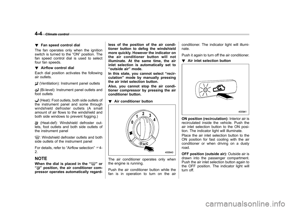
Each dial position activates the following
air outlets.
(Ventilation): Instrument panel outlets
(Bi-level): Instrument panel outlets and
foot outlets
(Heat): Foot outlets, both side outlets of
the instrument panel and some through
windshield defroster outlets (A small
amount of air flows to the windshield and
both side windows to prevent fogging.)
(Heat-def): Windshield defroster out-
lets, foot outlets and both side outlets of
the instrument panel
: Windshield defroster outlets and both
side outlets of the instrument panel
For details, refer to “Airflow selection ”F 4-
2. NOTE
When the dial is placed in the “
”or
“” position, the air conditioner com-
pressor operates automatically regard- less of the position of the air condi-
tioner button to defog the windshield
more quickly. However the indicator on
the air conditioner button will not
illuminate. At the same time, the air
inlet selection is automatically set to“
outside air ”mode.
In this state, you cannot select “recir-
culation ”mode by manually pressing
the air inlet selection button.
Also, you cannot stop the air condi-
tioner compressor by pressing the air
conditioner button. ! Air conditioner button
The air conditioner operates only when
the engine is running.
Push the air conditioner button while the
fan is in operation to turn on the air conditioner. The indicator light will illumi-nate.
Push it again to turn off the air conditioner. !
Air inlet selection button
ON position (recirculation): Interior air is
recirculated inside the vehicle. Push the
air inlet selection button to the ON posi-
tion. The indicator light will illuminate.
Place the air inlet selection button to the
ON position for fast cooling with the air
conditioner or when driving on a dustyroad.
OFF position (outside air): Outside air is
drawn into the passenger compartment.
Push the air inlet selection button again to
the OFF position. The indicator light will
turn off.
Page 176 of 458

Place the air inlet selection button to the
OFF position when the interior has cooled
to a comfortable temperature and the road
is no longer dusty.
WARNING
Continued operation with the air
inletselectionbuttonintheON
position may fog up the windows.
Switch to the OFF position as soon
as the outside dusty conditionclears.
& Heater operation
NOTE . When the “
”or “”position is
selected, the air conditioner compres-
sor automatically operates regardless
of the position of the air conditioner
button to defog the windshield more
quickly. At the same time, the air inlet
selection is automatically switched to
the OFF position (outside air). How-
ever, the air conditioner indicator light
does not illuminate at this time.. When defrosting, defogging or heat-
ing, warm air is also emitted from the
right and left air outlets. To stop warm
airflow from these outlets, turn the
corresponding thumb wheel down. !
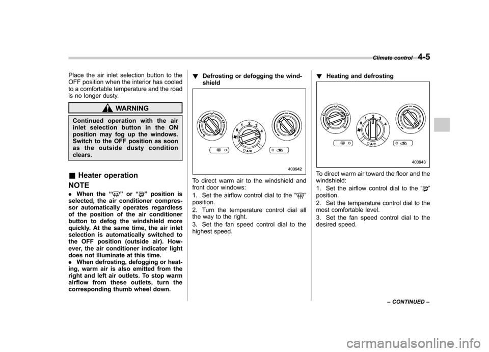
Defrosting or defogging the wind-shield
To direct warm air to the windshield and
front door windows:
1. Set the airflow control dial to the “
”
position.
2. Turn the temperature control dial all
the way to the right.
3. Set the fan speed control dial to the
highest speed. !
Heating and defrosting
To direct warm air toward the floor and the windshield:
1. Set the airflow control dial to the “
”
position.
2. Set the temperature control dial to the
most comfortable level.
3. Set the fan speed control dial to the
desired speed. Climate control
4-5
– CONTINUED –
Page 177 of 458

4-6Climate control
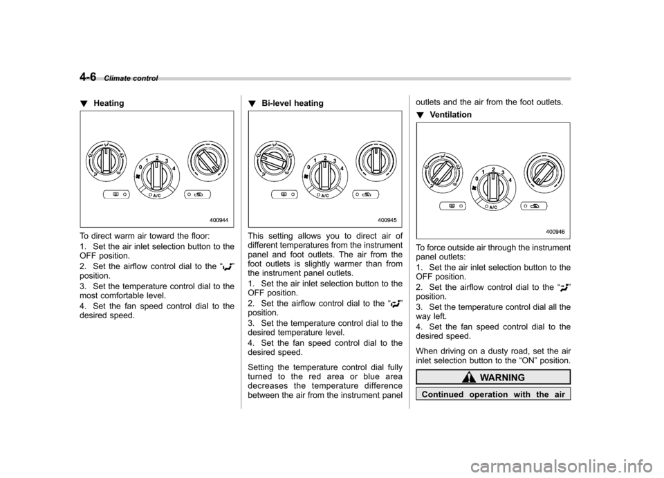
!Heating
To direct warm air toward the floor:
1. Set the air inlet selection button to the
OFF position.
2. Set the airflow control dial to the “
”
position.
3. Set the temperature control dial to the
most comfortable level.
4. Set the fan speed control dial to the
desired speed. !
Bi-level heating
This setting allows you to direct air of
different temperatures from the instrument
panel and foot outlets. The air from the
foot outlets is slightly warmer than from
the instrument panel outlets.
1. Set the air inlet selection button to the
OFF position.
2. Set the airflow control dial to the “
”
position.
3. Set the temperature control dial to the
desired temperature level.
4. Set the fan speed control dial to the
desired speed.
Setting the temperature control dial fully
turned to the red area or blue area
decreases the temperature difference
between the air from the instrument panel outlets and the air from the foot outlets. !
Ventilation
To force outside air through the instrument
panel outlets:
1. Set the air inlet selection button to the
OFF position.
2. Set the airflow control dial to the “
”
position.
3. Set the temperature control dial all the
way left.
4. Set the fan speed control dial to the
desired speed.
When driving on a dusty road, set the air
inlet selection button to the “ON ”position.
WARNING
Continued operation with the air
Page 178 of 458

inletselectionbuttonintheON
position may fog up the windows.
Switch to the OFF position as soon
as the outside dusty conditionclears.
& Air conditioner operation
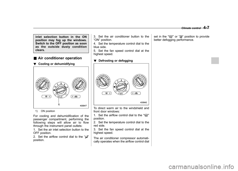
! Cooling or dehumidifying
1) ON position
For cooling and dehumidification of the
passenger compartment, performing the
following steps will allow air to flow
through the instrument panel outlets:
1. Set the air inlet selection button to the
OFF position.
2. Set the airflow control dial to the “
”
position. 3. Set the air conditioner button to the “
ON ”position.
4. Set the temperature control dial to the
blue side.
5. Set the fan speed control dial at the
highest speed. ! Defrosting or defogging
To direct warm air to the windshield and
front door windows:
1. Set the airflow control dial to the “
”
position.
2. Set the temperature control dial to the
red side.
3. Set the fan speed control dial at the
highest speed.
The air conditioner compressor automati-
cally operates when the airflow control dial set in the
“
”or “”position to provide
better defogging performance. Climate control
4-7
Page 179 of 458

4-8Climate control
Automatic climate control
system (if equipped)
Although this climate control system can
be used as a full-automatic climate control
system, it can also, if desired, be used as
a semi-automatic climate control system.
When it is used as a full-automatic climate
control system, the outlet air temperature,
fan speed, airflow distribution, air inlet
control, and air conditioner compressor
operation are all automatically controlled
to maintain a constant, comfortable tem-
perature inside the vehicle. NOTE .Operate the automatic climate con-
trol system when the engine is running. . When the engine coolant is cold, the
blower does not run.. In the “AUTO ”mode, when the air
temperature in the passenger compart-
ment is sufficiently cool, the air condi-
tioner compressor does not operate.
For efficient defogging or dehumidify-
ing in cold weather, press the “A/C ”
button to operate the air conditioner
compressor. &
Control panel
1) Temperature control dial
2) Fan speed control dial
3) Airflow control dial
4) Control switch of the defogger and deicer
system (Refer to “Defogger and deicer ”
F 3-48.)
5) Air inlet selection button
6) Air conditioner button &
To use as full-automatic cli-
mate control system
Place the temperature control dial in the
position for your desired temperature, then
set the other dials and buttons as de-
scribed in the following. The system ’s
functions will then switch to AUTO mode
and be controlled automatically. . Airflow control dial: AUTO position
. Fan speed control dial: AUTO position
& To use as semi-automatic
climate control system
Each function can be individually set to
AUTO mode independently of the others.
Any function set to AUTO mode is con-
trolled automatically. Any function not set
to AUTO mode can be manually adjusted
as desired.
The temperature can be set within a range
of 65 to 85 8F (20 to 30 8C).
Page 180 of 458

&Fan speed control dial
The fan operates only with the ignition
switch in the ON position. The fan speed
control dial is used to select the AUTO
(automatic control) mode or to select the
desired fan speed. The dial ’s positions
and their functions are as follows. OFF: The fan does not operate.
AUTO: The fan speed is adjusted auto-
maticallyinaccordancewiththeair
temperature inside and outside the pas-
senger compartment, the intensity of sun-
light, and other factors. SUBARU recom-
mends using the AUTO position.
Other positions: The fan speed can be
adjusted in 7 steps. NOTE
With the fan speed control dial in the
AUTO position and the airflow control
dial in the
“
”, “”,or “”position,
the fan does not operate during engine
warm-up until the engine coolant tem-
perature exceeds approximately 122 8F
(50 8C).
& Temperature control dial
This dial is used to set the desired interior
temperature. With the dial set to your
desired temperature, the system automa-
tically adjusts the temperature of air
supplied from the outlets such that the
desired temperature is achieved andmaintained.
If the dial is turned fully counterclockwise, the system gives maximum cooling per-
formance. If the dial is turned fully clock-
wise, the system gives maximum heatingperformance. &
Airflow control dial
Each dial position activates the following
air outlets. AUTO: The airflow control is adjusted
automatically in accordance with the air
temperature inside and outside the pas-
senger compartment, the intensity of sun-
light, and other factors. SUBARU recom-
mends using the AUTO position.
(Ventilation): Instrument panel outlets
(Bi-level): Instrument panel outlets and
foot outlets
(Heat): Foot outlets, both side outlets of Climate control
4-9
– CONTINUED –