tow SUBARU IMPREZA WRX STI 2012 User Guide
[x] Cancel search | Manufacturer: SUBARU, Model Year: 2012, Model line: IMPREZA WRX STI, Model: SUBARU IMPREZA WRX STI 2012Pages: 463, PDF Size: 7.69 MB
Page 167 of 463
Black plate (121,1)
北米Model "A1130BE-A" EDITED: 2011/ 6/ 7
Ignition switch
WARNING
. Never turn the ignition switch to
“ LOCK” while the vehicle is
being driven or towed because
that will lock the steering wheel,
preventing steering control. And
when the engine is turned off, it
takes a much greater effort than
usual to steer.
. Before leaving the vehicle, al-
ways remove the key from the
ignition switch for safety and
never allow an unattended child
to remain in the vehicle. Failure
to follow this procedure could
result in injury to a child or
others. Children could operate
the power windows, the moon-
roof or other controls or even
make the vehicle move.
CAUTION
Do not attach a large key holder or
key case to either key. If it banged
against your knees or hands while
you are driving, it could turn the
ignition switch from the “ON ”posi- tion to the
“Acc ”or “LOCK ”posi-
tion, thereby stopping the engine.
Also, if the key is attached to a
keyholder or to a large bunch of
other keys, centrifugal force may act
on it as the vehicle moves, resulting
in unwanted turning of the ignition
switch.
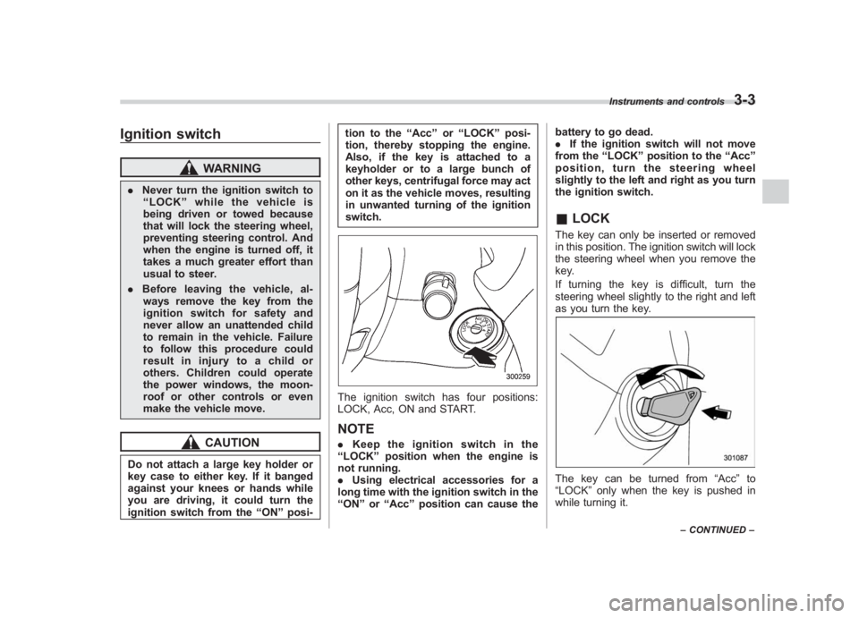
The ignition switch has four positions:
LOCK, Acc, ON and START.NOTE. Keep the ignition switch in the
“ LOCK ”position when the engine is
not running.
. Using electrical accessories for a
long time with the ignition switch in the
“ ON ”or “Acc ”position can cause the battery to go dead.
.
If the ignition switch will not move
from the “LOCK ”position to the “Acc ”
position, turn the steering wheel
slightly to the left and right as you turn
the ignition switch.
& LOCKThe key can only be inserted or removed
in this position. The ignition switch will lock
the steering wheel when you remove the
key.
If turning the key is difficult, turn the
steering wheel slightly to the right and left
as you turn the key.The key can be turned from “Acc”to
“LOCK ”only when the key is pushed in
while turning it.
Instruments and controls
3-3
– CONTINUED –
3
Page 183 of 463
Black plate (137,1)
北米Model "A1130BE-A" EDITED: 2011/ 6/ 7
When the battery becomes fully charged,
the light will turn off.&
Brake system
warning light
WARNING
. Driving with the brake system
warning light on is dangerous.
This indicates your brake system
may not be working properly. If
the light remains illuminated,
have the brakes inspected by a
SUBARU dealer immediately.
. If at all in doubt about whether
the brakes are operating prop-
erly, do not drive the vehicle.
Have your vehicle towed to the
nearest SUBARU dealer for re-
pair.
This light has the following functions.
! Parking brake warning
The light illuminates with the parking
brake applied while the ignition switch is
in the “ON”position. It turns off when the
parking brake is fully released.
! Brake fluid level warning
This light illuminates when the brake fluid
level has dropped to near the “MIN”level of the brake fluid reservoir with the ignition
switch in the
“ON”position and with the
parking brake fully released.
If the brake system warning light should
illuminate while driving (with the parking
brake fully released and with the ignition
switch positioned in “ON ”), it could be an
indication of leaking of brake fluid or worn
brake pads. If this occurs, immediately
stop the vehicle at the nearest safe place
and check the brake fluid level. If the fluid
level is below the “MIN ”mark in the
reservoir, do not drive the vehicle. Have
the vehicle towed to the nearest SUBARU
dealer for repair.
! Electronic Brake Force Distribution
(EBD) system warning
The brake system warning light also
illuminates if a malfunction occurs in the
EBD system. In that event, it illuminates
together with the ABS warning light.
The EBD system may be malfunctioning if
the brake system warning light and ABS
warning light illuminate simultaneously
during driving.
Even if the EBD system fails, the conven-
tional braking system will still function.
However, the rear wheels will be more
prone to locking when the brakes are
applied harder than usual and the vehi-
cle ’s motion may therefore become some- what harder to control.
If the brake system warning light and ABS
warning light illuminate simultaneously,
take the following steps.
1. Stop the vehicle in the nearest safe,
flat place.
2. Shut down the engine, apply the
parking brake and then restart it.
3. Release the parking brake. If both
warning lights turn off, the EBD system
may be malfunctioning. Drive carefully to
the nearest SUBARU dealer and have the
system inspected.
4. If both warning lights illuminate again
and remain illuminated after the engine
has been restarted, shut down the engine
again, apply the parking brake, and check
the brake fluid level.
5. If the brake fluid level is not below the
“MIN
”mark, the EBD system may be
malfunctioning. Drive carefully to the
nearest SUBARU dealer and have the
system inspected.
6. If the brake fluid level is below the
“MIN ”mark, DO NOT drive the vehicle.
Instead, have the vehicle towed to the
nearest SUBARU dealer for repair.
Instruments and controls
3-19
– CONTINUED –
3
Page 194 of 463
Black plate (148,1)
北米Model "A1130BE-A" EDITED: 2011/ 6/ 7
3-30
Instruments and controls
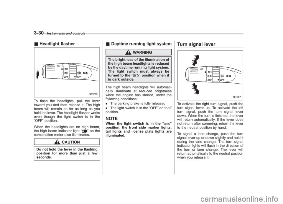
& Headlight flasherTo flash the headlights, pull the lever
toward you and then release it. The high
beam will remain on for as long as you
hold the lever. The headlight flasher works
even though the light switch is in the
“OFF ”position.
When the headlights are on high beam,
the high beam indicator light “
”on the
combination meter also illuminates.
CAUTION
Do not hold the lever in the flashing
position for more than just a few
seconds.
& Daytime running light system
WARNING
The brightness of the illumination of
the high beam headlights is reduced
by the daytime running light system.
The light switch must always be
turned to the “
”position when it
is dark outside.
The high beam headlights will automati-
cally illuminate at reduced brightness
when the engine has started, under the
following conditions:
. The parking brake is fully released.
. The light switch is in the “OFF”or “
”
position.
NOTEWhen the light switch is in the “
”
position, the front side marker lights,
tail lights and license plate lights are
illuminated.
Turn signal leverTo activate the right turn signal, push the
turn signal lever up. To activate the left
turn signal, push the turn signal lever
down. When the turn is finished, the lever
will return automatically. If the lever does
not return after cornering, return the lever
to the neutral position by hand.
To signal a lane change, push the turn
signal lever up or down slightly and hold it
during the lane change. The turn signal
indicator lights will flash in the direction of
the turn or lane change. The lever will
return automatically to the neutral position
when you release it.
Page 199 of 463
Black plate (153,1)
北米Model "A1130BE-A" EDITED: 2011/ 6/ 7
& Windshield wiper and washer
switchesThe wiper operates only when the ignition
switch is in the “ON”or “Acc ”position.
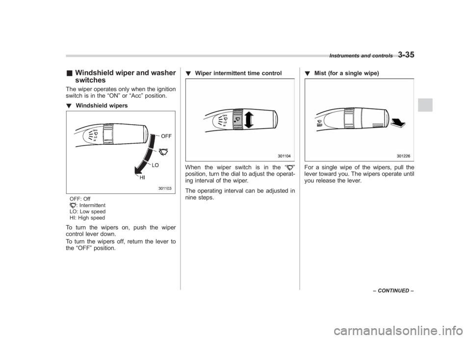
! Windshield wipersOFF: Off: Intermittent
LO: Low speed
HI: High speed
To turn the wipers on, push the wiper
control lever down.
To turn the wipers off, return the lever to
the “OFF ”position. !
Wiper intermittent time control
When the wiper switch is in the “
”
position, turn the dial to adjust the operat-
ing interval of the wiper.
The operating interval can be adjusted in
nine steps. !
Mist (for a single wipe)
For a single wipe of the wipers, pull the
lever toward you. The wipers operate until
you release the lever.
Instruments and controls
3-35
–CONTINUED –
3
Page 201 of 463
Black plate (155,1)
北米Model "A1130BE-A" EDITED: 2011/ 6/ 7
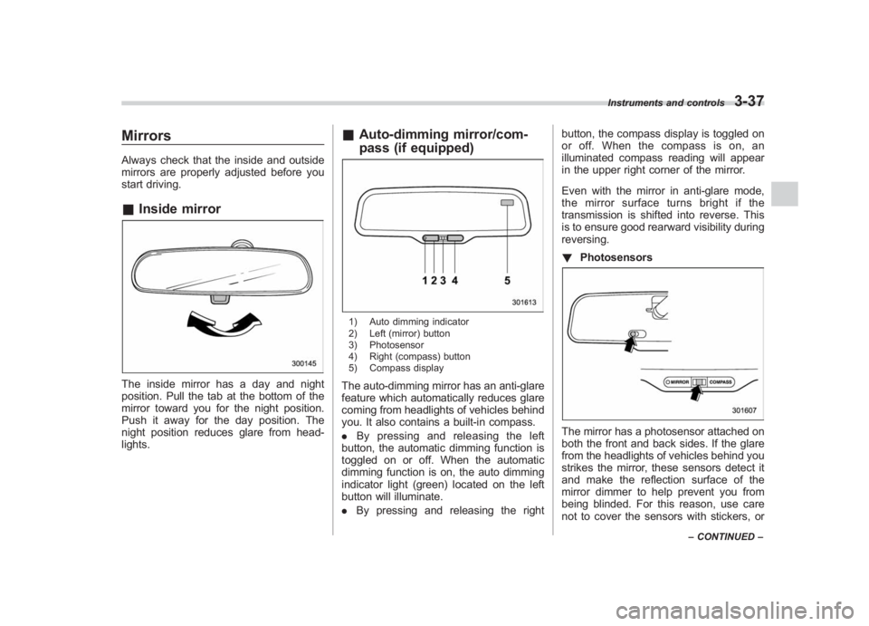
MirrorsAlways check that the inside and outside
mirrors are properly adjusted before you
start driving.& Inside mirrorThe inside mirror has a day and night
position. Pull the tab at the bottom of the
mirror toward you for the night position.
Push it away for the day position. The
night position reduces glare from head-
lights.
&Auto-dimming mirror/com-
pass (if equipped)1) Auto dimming indicator
2) Left (mirror) button
3) Photosensor
4) Right (compass) button
5) Compass displayThe auto-dimming mirror has an anti-glare
feature which automatically reduces glare
coming from headlights of vehicles behind
you. It also contains a built-in compass.
. By pressing and releasing the left
button, the automatic dimming function is
toggled on or off. When the automatic
dimming function is on, the auto dimming
indicator light (green) located on the left
button will illuminate.
. By pressing and releasing the right button, the compass display is toggled on
or off. When the compass is on, an
illuminated compass reading will appear
in the upper right corner of the mirror.
Even with the mirror in anti-glare mode,
the mirror surface turns bright if the
transmission is shifted into reverse. This
is to ensure good rearward visibility during
reversing.
!
Photosensors
The mirror has a photosensor attached on
both the front and back sides. If the glare
from the headlights of vehicles behind you
strikes the mirror, these sensors detect it
and make the reflection surface of the
mirror dimmer to help prevent you from
being blinded. For this reason, use care
not to cover the sensors with stickers, or
Instruments and controls
3-37
–CONTINUED –
3
Page 203 of 463
Black plate (157,1)
北米Model "A1130BE-A" EDITED: 2011/ 6/ 7
dimming function is on, the LED indicator
will illuminate.
Even with the mirror in the automatic
dimming mode, the mirror surface turns
bright if the transmission is shifted into
reverse. This is to ensure good rearward
visibility during reversing.
. By pressing the compass display but-
ton, the compass display is toggled on or
off. When the compass is on, an illumi-
nated compass reading will appear in the
upper right corner of the mirror.
When cleaning the mirror, use a paper
towel or similar material dampened with
glass cleaner. Do not spray glass cleaner
directly on the mirror as that may cause
theliquidcleanertoenterthemirror
housing and damage the mirror. !
Photosensors
The mirror has a photosensor attached on
both the front and back sides. During
nighttime driving, these sensors detect
distracting glare from vehicle headlights
behind you and automatically dim the
mirror to eliminate glare and preserve
your vision. For this reason, use care not
to cover the sensors with stickers, or other
similar items. Periodically wipe the sen-
sors clean using a piece of dry soft cotton
cloth or an applicator. !
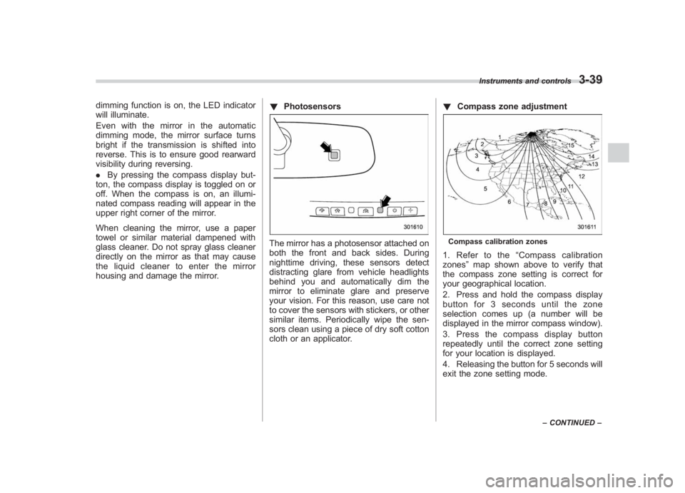
Compass zone adjustment
Compass calibration zones1. Refer to the “Compass calibration
zones” map shown above to verify that
the compass zone setting is correct for
your geographical location.
2. Press and hold the compass display
button for 3 seconds until the zone
selection comes up (a number will be
displayed in the mirror compass window).
3. Press the compass display button
repeatedly until the correct zone setting
for your location is displayed.
4. Releasing the button for 5 seconds will
exit the zone setting mode.
Instruments and controls
3-39
– CONTINUED –
3
Page 217 of 463
Black plate (173,1)
北米Model "A1130BE-A" EDITED: 2011/ 6/ 7
Place the air inlet selection button to the
OFF position when the interior has cooled
to a comfortable temperature and the road
is no longer dusty.
WARNING
Continued operation with the air
inletselectionbuttonintheON
position may fog up the windows.
Switch to the OFF position as soon
as the outside dusty condition
clears.& Heater operation
NOTE. When the “
”or “
”position is
selected, the air conditioner compres-
sor automatically operates regardless
of the position of the air conditioner
button to defog the windshield more
quickly. At the same time, the air inlet
selection is automatically switched to
the OFF position (outside air). How-
ever, the air conditioner indicator light
does not illuminate at this time.
. When defrosting, defogging or heat-
ing, warm air is also emitted from the
right and left air outlets. To stop warm
airflow from these outlets, turn the
corresponding thumb wheel down. !
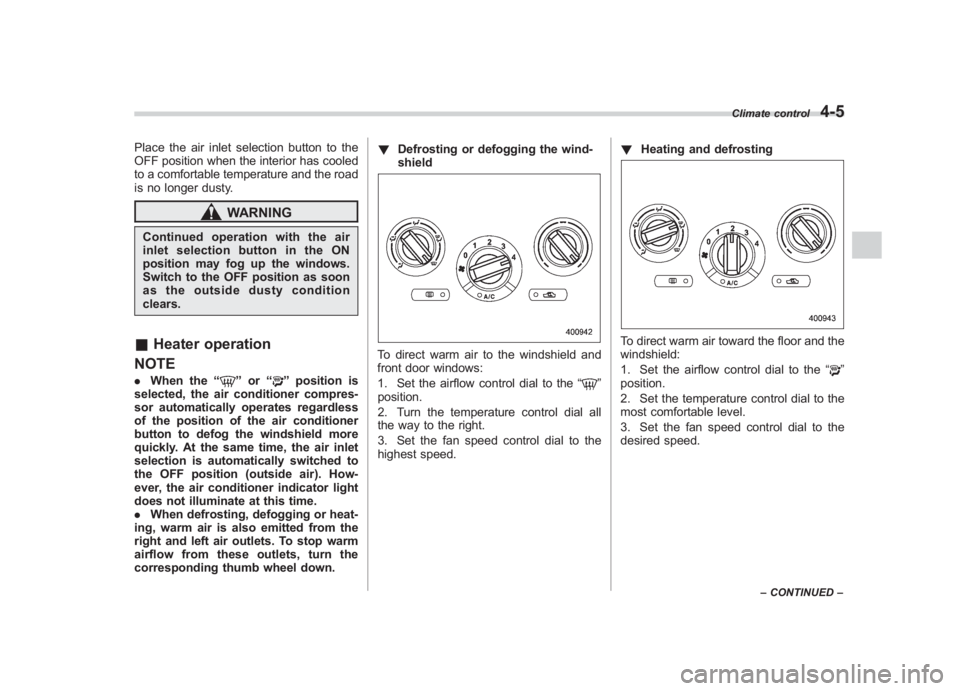
Defrosting or defogging the wind-
shield
To direct warm air to the windshield and
front door windows:
1. Set the airflow control dial to the “
”
position.
2. Turn the temperature control dial all
the way to the right.
3. Set the fan speed control dial to the
highest speed. !
Heating and defrosting
To direct warm air toward the floor and the
windshield:
1. Set the airflow control dial to the “
”
position.
2. Set the temperature control dial to the
most comfortable level.
3. Set the fan speed control dial to the
desired speed.
Climate control
4-5
– CONTINUED –
4
Page 218 of 463
Black plate (174,1)
北米Model "A1130BE-A" EDITED: 2011/ 6/ 7
4-6
Climate control
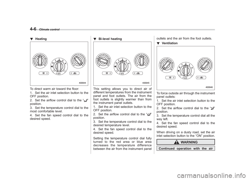
! HeatingTo direct warm air toward the floor:
1. Set the air inlet selection button to the
OFF position.
2. Set the airflow control dial to the “
”
position.
3. Set the temperature control dial to the
most comfortable level.
4. Set the fan speed control dial to the
desired speed. !
Bi-level heating
This setting allows you to direct air of
different temperatures from the instrument
panel and foot outlets. The air from the
foot outlets is slightly warmer than from
the instrument panel outlets.
1. Set the air inlet selection button to the
OFF position.
2. Set the airflow control dial to the “
”
position.
3. Set the temperature control dial to the
desired temperature level.
4. Set the fan speed control dial to the
desired speed.
Setting the temperature control dial fully
turned to the red area or blue area
decreases the temperature difference
between the air from the instrument panel outlets and the air from the foot outlets.
!
Ventilation
To force outside air through the instrument
panel outlets:
1. Set the air inlet selection button to the
OFF position.
2. Set the airflow control dial to the “
”
position.
3. Set the temperature control dial all the
way left.
4. Set the fan speed control dial to the
desired speed.
When driving on a dusty road, set the air
inlet selection button to the “ON”position.
WARNING
Continued operation with the air
Page 231 of 463
Black plate (187,1)
北米Model "A1130BE-A" EDITED: 2011/ 6/ 7
Antenna system& Roof antenna
CAUTION
. Be sure to lower the antenna rod
before entering garages, parking
towers and other locations with
low ceilings.
. Remove the antenna rod before
washing your car at a car wash. If
the antenna rod is left attached, it
may scratch the roof.
. When reinstalling the removed
antenna rod, be sure to fully
tighten it.
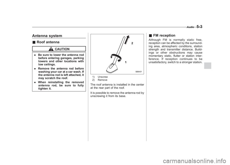
1) Unscrew
2) RemoveThe roof antenna is installed in the center
at the rear part of the roof.
It is possible to remove the antenna rod by
unscrewing it from its base.
& FM receptionAlthough FM is normally static free,
reception can be affected by the surround-
ing area, atmospheric conditions, station
strength and transmitter distance. Build-
ings or other obstructions may cause
momentary static, flutter or station inter-
ference. If reception continues to be
unsatisfactory, switch to a stronger station.
Audio
5-3
5
Page 264 of 463
Black plate (220,1)
北米Model "A1130BE-A" EDITED: 2011/ 6/ 7
5-36
Audio
. When the ignition switch is turned to
the “LOCK ”position during a call, the
call may be disconnected or continued
on the cell phone depending on the
type of cell phone that is used. Note
that operation of the cell phone may be
necessary if the call is continued on the
cell phone.
. Do not speak at the same time as the
other party during a call. If you and the
party speak at the same time, it may be
difficult for the other party to hear your
voice and vice versa. This is normal.
. The receiver sound volume should
be set as low as possible. Otherwise,
the party you are calling may notice an
undesirable echo sound.
. Speak clearly and loudly.
. Your voice may be difficult to be
heard by the party under the following
conditions.
–Driving on a rough road.
– Driving at a high speed.
– Driving with a window open.
– When air from the ventilator
blows directly towards the micro-
phone.
– When the sound coming from the
ventilator is loud.
– When the cell phone is too close
to the microphone. .
The sound quality may degrade due
to the influence of the cell phone that is
connected to the system or the circum-
stances of the Bluetooth network.
. When another Bluetooth
®device is
simultaneously connected, noise may
be heard in the voice coming from the
hands-free phone.
! Corresponding profiles for the cell
phone
. HFP (Hands Free Profile): Ver. 1.0
. OPP (Object Push Profile): Ver. 1.1
&Certification for the Hands-
free system
CAUTION
FCC WARNING
Changes or modifications not ex-
pressly approved by the party re-
sponsible for compliance could void
the user ’s authority to operate the
equipment.NOTEThis device complies with Part 15 of
the FCC Rules and RSS-Gen of IC
Rules. Operation is subject to the
following two conditions: (1) this de- vice may not cause harmful interfer-
ence, and (2) this device must accept
any interference received, including
interference that may cause undesired
operation.
NOTEThis equipment has been tested and
found to comply with the limits for a
Class B digital device, pursuant to Part
15 of the FCC Rules. These limits are
designed to provide reasonable protec-
tion against harmful interference in a
residential installation. This equipment
may cause harmful interference to
radio communications, if it is not
installed and used in accordance with
the instructions. However, there is no
guarantee that interference will not
occur in a particular installation. If this
equipment does cause harmful inter-
ference to radio or television reception,
which can be determined by turning the
equipment off and on, the user is
encouraged to try to correct the inter-
ference by one or more of the following
measures.
.
Reorient or relocate the receiving
antenna.
. Increase the separation between the
equipment and receiver.
. Connect the equipment into an out-