air condition SUBARU LEGACY 1996 Service Repair Manual
[x] Cancel search | Manufacturer: SUBARU, Model Year: 1996, Model line: LEGACY, Model: SUBARU LEGACY 1996Pages: 2890, PDF Size: 61.9 MB
Page 2 of 2890

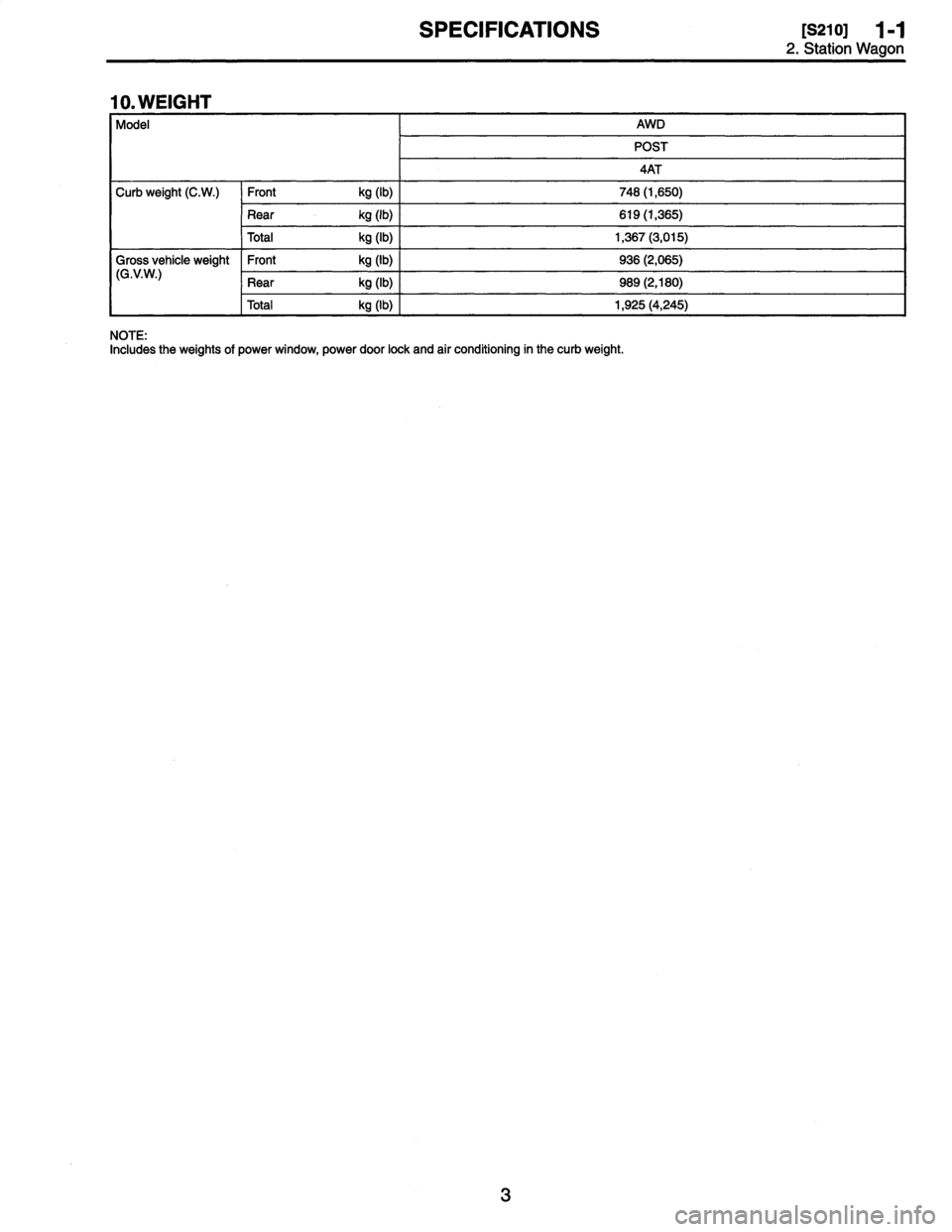
SPECIFICATIONS
[s21o1
1-1
2
.
Station
Wagon
10
.
WEIGHT
Model
AWD
POST
4AT
Curb
weight
(C
.W
.)
Front
kg
(1b)
748
(1,650)
Rear
kg
(1b)
619
(1,365)
Total
kg
(1b)
1,367
(3,015)
Gross
vehicle
weight
Front
kg
(1b)
936
(2,065)
(G
.V
.W
.)
Rear
kg
(1b)
9S9
(2,180)
Total
kg
(1b)
1,925
(4,245)
NOTE
:
Includes
the
weights
of
power
window,
power
door
lock
and
air
conditioning
in
the
curb
weight
.
Page 42 of 2890

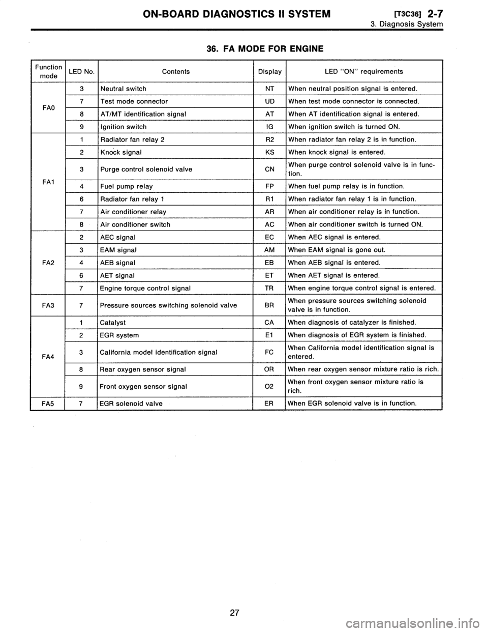
ON-BOARD
DIAGNOSTICS
II
SYSTEM
ITscas1
2-7
3
.
Diagnosis
System
36
.
FA
MODE
FOR
ENGINE
Function
mode
LED
No
.
Contents
Display
LED
"ON"
requirements
3Neutral
switch
NT
When
neutralposition
signal
is
entered
.
7Test
mode
connector
UD
When
test
mode
connector
is
connected
.
FAO
8
AT/MT
identification
signal
AT
When
AT
identification
signal
is
entered
.
9
Ignition
switchIG
When
ignition
switch
is
turned
ON
.
1
Radiator
fan
relay
2
R2
When
radiator
fanrelay2
isin
function
.
2
Knock
signal
KS
When
knock
signal
is
entered
.
3
Purge
control
solenoid
valve
CNWhen
purge
control
solenoid
valve
is
in
func-
tion
.
FA1
4Fuel
pump
relay
FP
When
fuel
pump
relay
isin
function
.
6
Radiator
fanrelay
1
R1
When
radiator
fanrelay
1
isin
function
.
7
Air
conditioner
relay
ARWhen
air
conditioner
relay
isin
function
.
8
Air
conditioner
switch
ACWhen
air
conditioner
switch
is
turned
ON
.
2
AEC
signal
ECWhen
AEC
signal
is
entered
.
3
EAM
signal
AM
When
EAM
signal
is
gone
out
.
FA2
4
AEB
signal
EB
When
AEB
signal
is
entered
.
6
AET
signal
ET
When
AET
signal
is
entered
.
7
Engine
torque
control
signal
TR
When
engine
torque
control
signal
is
entered
.
FA3
7
Pressure
sources
switching
solenoid
valve
BR
When
pressure
sources
switching
solenoid
valve
is
in
function
.
1
Catalyst
CA
When
diagnosis
of
catalyzer
is
finished
.
2
EGR
system
E1
When
diagnosis
of
EGR
system
is
finished
.
FA4
3
California
model
identification
signal
FC
When
California
model
identification
signal
is
entered
.
8
Rear
oxygen
sensor
signal
OR
When
rear
oxygen
sensor
mixture
ratio
is
rich
.
9Front
oxygen
sensor
signal
02
When
front
oxygen
sensor
mixture
ratio
is
rich
.
FA5
7
EGR
solenoid
valve
ER
When
EGR
solenoid
valve
is
in
function
.
27
Page 148 of 2890
![SUBARU LEGACY 1996 Service Repair Manual
SUPPLEMENTAL
RESTRAINT
SYSTEM
(ELECTRIC
SENSOR
TYPE)
[T4CO]
5-5b
4
.
Diagnostics
Chart
for
On-board
Diagnostic
System
2
L3141
B5mol
15B
2
33
E
;1
1~3141516
B5M01
16B
B
:
ON-BOARD
DIAGNOSTIC
W SUBARU LEGACY 1996 Service Repair Manual
SUPPLEMENTAL
RESTRAINT
SYSTEM
(ELECTRIC
SENSOR
TYPE)
[T4CO]
5-5b
4
.
Diagnostics
Chart
for
On-board
Diagnostic
System
2
L3141
B5mol
15B
2
33
E
;1
1~3141516
B5M01
16B
B
:
ON-BOARD
DIAGNOSTIC
W](/img/17/57433/w960_57433-147.png)
SUPPLEMENTAL
RESTRAINT
SYSTEM
(ELECTRIC
SENSOR
TYPE)
[T4CO]
5-5b
4
.
Diagnostics
Chart
for
On-board
Diagnostic
System
2
L3141
B5mol
15B
2
33
E
;1
1~3141516
B5M01
16B
B
:
ON-BOARD
DIAGNOSTIC
When
the
airbag
system
isin
functioning
condition,
the
airbag
warning
light
will
remain
on
for
8
seconds
and
go
out
when
the
ignition
switch
is
set
to
ON
.
If
there
is
any
malfunction,
the
airbag
warning
light
will
either
stay
on
or
off
continuously
.
In
such
cases,
perform
on-board
diagnostic
in
accordance
with
the
specified
pro-
cedure
to
determine
trouble
codes
.
1)
Turn
ignition
switch
ON
(with
engine
OFF)
.
2)
ConnectDIAG
.
terminal
T
to
No
.
1
terminal
of
diag-
nosis
connector
~2
located
below
lower
cover
.
3)
Check
in
accordance
with
the
trouble
code
indicated
by
the
AIRBAG
warning
light,
and
record
the
trouble
codes
.
4)
Turn
the
ignition
switch
"OFF"
and
remove
the
DIAL
.
terminal
from
No
.1
terminal
of
diagnosis
connector
.
C
:
CLEAR
MEMORY
After
eliminating
problem
as
per
trouble
code,
clear
mem-
oryas
follows
:
Make
sure
ignition
switch
is
ON
(and
engine
off)
.
Connect
one
DIAL
.
terminal
1Q
on
diagnosis
connector
(Z
termi-
nal
No
.
1
.
While
warning
light
is
flashing,
connect
the
other
DIAL
.
terminal
(Z
on
terminal
No
.
2
for
at
least
three
seconds
.
After
memory
is
cleared,
normal
warning
light
flashing
rate
resumes
.
(Warning
light
flashes
every
0
.6
seconds
ON-OFF
operation
.)
Memory
cannotbe
cleared
if
any
problem
exists
.
After
clear
memory
and
then
DIAG
.
terminals
(1)
and
(3),
extract
from
diagnosis
connector
02
.
9
Page 179 of 2890

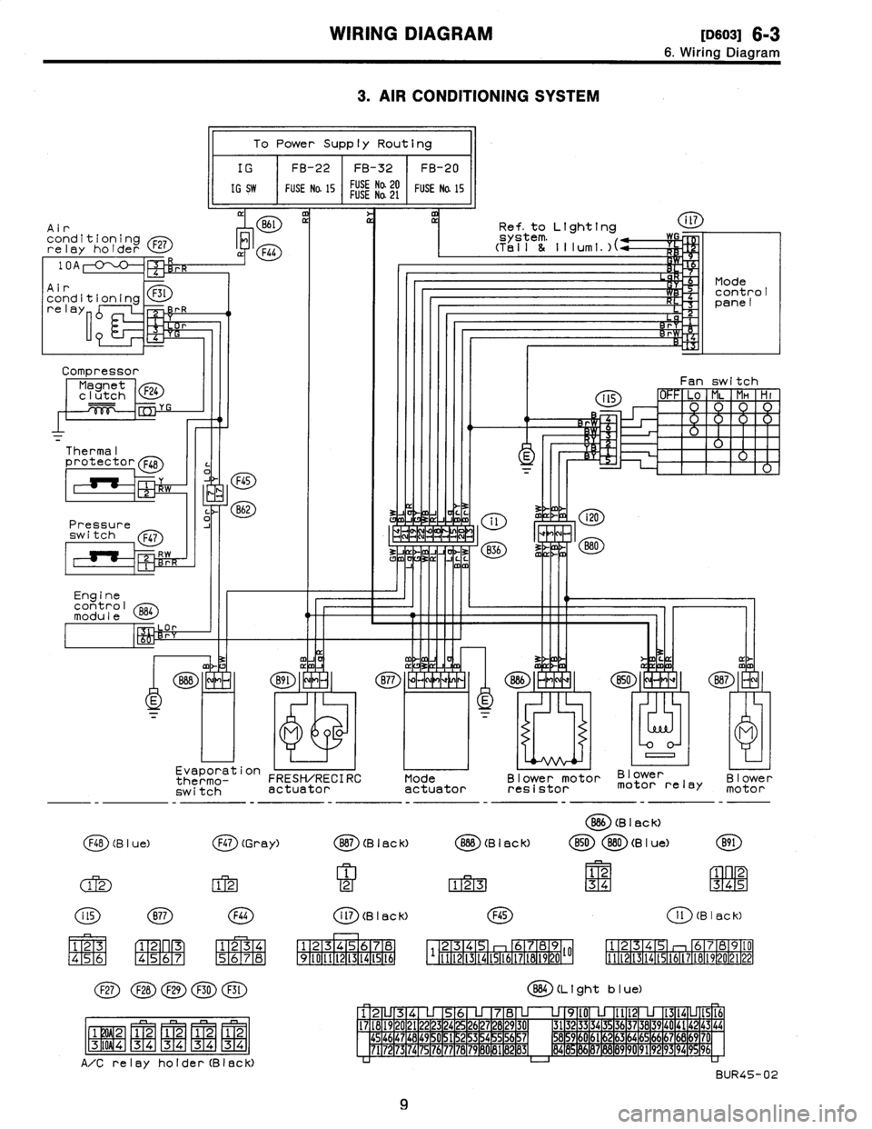
WIRING
DIAGRAM
[113so31
6-3
6
.
Wiring
Diagram
3
.
AIR
CONDITIONING
SYSTEM
Air
conditioningrelay
holder
F27
Compressor
Magnet
F24
clutch
Thermal
protector
F48
Pressure
switch
Q47
Engine
control
module
l
a
p
To
Power
Supply
Routing
IG
FB-22
FB-32
FB-20
IG
SW
FUSE
Na
15
FUSE
Na20FUSENa
21
FUSE
Na
15
M
11
Evaporation
thermo-
FRESH/RECIRC
switch
actuator
F48
(B
I
ue)
(j~)
(Gr
ay)
(M
FIT2-1
123
45
6
C1-
F2~
n
R3
[4151617
1
234
(~D(~D(~D
(~~D
(E)
j
F1W2-1
1
2
1
2
1
2
1
2-
-
-
MMMM
F3T
i
0
9
4
1
3
4
34
34
34
A/Crelay
holder(Black)
Mode
actuator
Ref
.
to
Lighting
Blower
motor
Blower
resistor
motor
relay
O
(B
I
ac
k)
Blower
motor
B87
(B
I
ac
k)
O
(B
I
ac
k)
B50880
(B
I
ue)
B91
1
12
1
2
123
34
345
i
ll
(B
I
ac
k)F45
1
l
(B
I
ac
k)
1
234S
I
6
1
7
1
12345
b789
125
6789(0
34
I1121314t516171819202122
1
9
1
10
1
11
1
12
1
13
1
14
1
15
1
t6
111121314t51617t81920~~
BB4
(L
t
ght
b
I
ue)
12U34
U
56
U
78
U
U
9l0
U
Ilt2
U
1314LJ1516
17
1
18
1
19
1
20
1
21
1
22
1
23
1
24
1
25
1
26
1
27
1
28
1
29
1
30
1
31323
3
34
35
3637
38
39
40
4142
43
44454647
1
48
1
49
~
0
1
51
1
52
1
53
1
54
~
5
1
56
1
57
1
M59
1
60
1
61
~
2
1
63
1
64
1
65
1
66
1
67
1
66
1
69
1
7'
7172
73
74
75
76777B7980
81
1
89
1
83
1
84
8
86878889
90
9192
93
94
996
BUR45-02
9
Page 183 of 2890
![SUBARU LEGACY 1996 Service Repair Manual
WIRING
DIAGRAM
(D6013]
6-3
6
.
Wiring
Diagram
Data
link
connector
Test
mode
B78
B75
~
B76
r
J
-j
mm
C
0
J
4
m
1Ref
.
to
Air
/conditioning
system
.
1Ref
.to
Radiator
~-----s
/
f
an
system
.
10
SUBARU LEGACY 1996 Service Repair Manual
WIRING
DIAGRAM
(D6013]
6-3
6
.
Wiring
Diagram
Data
link
connector
Test
mode
B78
B75
~
B76
r
J
-j
mm
C
0
J
4
m
1Ref
.
to
Air
/conditioning
system
.
1Ref
.to
Radiator
~-----s
/
f
an
system
.
10](/img/17/57433/w960_57433-182.png)
WIRING
DIAGRAM
(D6013]
6-3
6
.
Wiring
Diagram
Data
link
connector
Test
mode
B78
B75
~
B76
r
J
-j
mm
C
0
J
4
m
1Ref
.
to
Air
/conditioning
system
.
1Ref
.to
Radiator
~-----s
/
f
an
system
.
10
.
ef
.
toAT
control
R
system,
/L
a
F
m
3
L
o
P
~t
P
O
Engine
B86
control
module
m
M
s
D
j
i
E
v
v
.
.
.
.
l
J
"
-
N
819
8l
BIB
~
B19
f
~
T5
..
..
a
""
CD
Pressure
Front
sources
oxygenswitching
sensor,
~~
i
A
.,n
;H
B75
(Green)
2
Bt8
(Dark
gray)
21
3
CF
Rear
oxygensensor
(California
model)
Rear
oxygensensor
valve
(Othermodels)
B76
(Green)
Bl
(Brown)
Bl9
T6
(Grey)
878
(Y
e
II
ow)
IFNI
12
75
56789
B40
(Grey)
(BBD
(L
i
ghtb
I
ue)
12345678
910111213141516
1
23
4
56
7
8
9
l0
U
l213
14
15
16
17
1819
20
1
22232426
27
28
293
03
132
33
343
5
3637
38
39
4
0
4142
43
44
45
1
46
1
47
1
48
1
49
1
5051
253
54
S5
56S7
5
859
60616
263
64656661
6869
70
71
7273747576777879
80
818283
84
85
1
86
1
87
1
88
1
89
1
90
91
92
93949596
BUR10-02B
13
OBD-1l
service
connector
840
Page 186 of 2890
![SUBARU LEGACY 1996 Service Repair Manual
6-3
[oso2s]
WIRING
DIAGRAM
6
.
Wiring
Diagram
23
.
RADIATOR
FAN
SYSTEM
Diode
(A/C)
Main
fan
motor
oi3~
Subfen
motor
C
~
Flb
(B
leCk)
F43
(Orange)
Fl7
(B
I
ec
K)
(~D(~~(~D
QD
1
2
1
2
[3ql2
SUBARU LEGACY 1996 Service Repair Manual
6-3
[oso2s]
WIRING
DIAGRAM
6
.
Wiring
Diagram
23
.
RADIATOR
FAN
SYSTEM
Diode
(A/C)
Main
fan
motor
oi3~
Subfen
motor
C
~
Flb
(B
leCk)
F43
(Orange)
Fl7
(B
I
ec
K)
(~D(~~(~D
QD
1
2
1
2
[3ql2](/img/17/57433/w960_57433-185.png)
6-3
[oso2s]
WIRING
DIAGRAM
6
.
Wiring
Diagram
23
.
RADIATOR
FAN
SYSTEM
Diode
(A/C)
Main
fan
motor
oi3~
Subfen
motor
C
~
Flb
(B
leCk)
F43
(Orange)
Fl7
(B
I
ec
K)
(~D(~~(~D
QD
1
2
1
2
[3ql2
4
34
P34
34
A/C
relay
holder(Black)
F44
1234
5678
Engine
control
module
al
I
Air
conditioning
relay
holder
10A
F27
Main
fan
relay-1
F28
Ma
i
nfan
F30
Mr
relay-2
Sub
fan
F29
o
D
relay-2
F45
234
6789
1
1112131415161718192010
884
(L
1
ght
b
I
ue)
12
345678
9l0
lit213141516
17181920212
3242526
78
930
313233343
363738394
4142434445464748
1
49
~
1]
1
51
~
2
15
3
1
54
~
5
56
7
58
59
0
6l
62
63
4
65
66
67
68
9
70
7172
7374
7
76
77
78
79
8
8182
83
84
8
96
87
9
9
192
9394
9
96
BUR14-02
16
Page 208 of 2890
![SUBARU LEGACY 1996 Service Repair Manual
AUTOMATIC
TRANSMISSION
AND
DIFFERENTIAL
[Taoo]
3-2
8
.
Diagnostic
Chart
withSelect
Monitor
THVCC
(F14)
5
.2
V
83M0259
Probable
cause
(Item
outside
"specified
data")
1
1
.
Throttleposition
senso SUBARU LEGACY 1996 Service Repair Manual
AUTOMATIC
TRANSMISSION
AND
DIFFERENTIAL
[Taoo]
3-2
8
.
Diagnostic
Chart
withSelect
Monitor
THVCC
(F14)
5
.2
V
83M0259
Probable
cause
(Item
outside
"specified
data")
1
1
.
Throttleposition
senso](/img/17/57433/w960_57433-207.png)
AUTOMATIC
TRANSMISSION
AND
DIFFERENTIAL
[Taoo]
3-2
8
.
Diagnostic
Chart
withSelect
Monitor
THVCC
(F14)
5
.2
V
83M0259
Probable
cause
(Item
outside
"specified
data")
1
1
.
Throttleposition
sensor
power
supply
N
:
MODE
F14
-
THROTTLE
POSITION
SENSOR
POWER
SUPPLY
(THVCC)
-
CONDITION
:
Ignition
switch
ON
(engine
OFF)
SPECIFIED
DATA
:
5
.12f0
.1
V
Check
throttle
sensor
line
.
<
Ref
.
to
3-2
[T7L0]
.*2
>
OK
AFM
(F15)
0
.6V
83M0370
Probable
cause
(if
outside
"specified
data")
1
.
Mass
air
flow
signal
Check
performance
characteristics
of
mass
air
flow
signal
.
to
3-2
[T7H0]
.*2>
OK
Check
TCM
and
replace
if
necessary
.
O
:
MODE
F15
-
MASS
AIR
FLOW
SIGNAL
(AFM)
-
CONDITION
:
"
Ignition
switch
ON
(engine
ON)
"N
range
Idling
SPECIFIED
DATA
:
Engine
warm-up
:
0
.5
-
1
.22
V
I
Check
TCM
and
replace
if
necessary
.
19
Page 221 of 2890
![SUBARU LEGACY 1996 Service Repair Manual 2-7
[T10BOa]
ON-BOARD
DIAGNOSTICS
II
SYSTEM
10
.
Diagnostics
Chart
with
Trouble
Code
OBD
(FBI)
P0180
<TNKT>
H2M1306
BO
:
DTC
P0180
-
FUEL
TEMPERATURE
SENSOR
A
CIRCUIT
MALFUNCTION
(TNKT)
-
DTC
SUBARU LEGACY 1996 Service Repair Manual 2-7
[T10BOa]
ON-BOARD
DIAGNOSTICS
II
SYSTEM
10
.
Diagnostics
Chart
with
Trouble
Code
OBD
(FBI)
P0180
<TNKT>
H2M1306
BO
:
DTC
P0180
-
FUEL
TEMPERATURE
SENSOR
A
CIRCUIT
MALFUNCTION
(TNKT)
-
DTC](/img/17/57433/w960_57433-220.png)
2-7
[T10BOa]
ON-BOARD
DIAGNOSTICS
II
SYSTEM
10
.
Diagnostics
Chart
with
Trouble
Code
OBD
(FBI)
P0180
H2M1306
BO
:
DTC
P0180
-
FUEL
TEMPERATURE
SENSOR
A
CIRCUIT
MALFUNCTION
(TNKT)
-
DTC
DETECTING
CONDITION
:
e
Immediately
at
fault
recognition
10801
Connect
Subaru
Select
Monitor
or
the
OBD-11
general
scan
tool,
and
read
data
.
10802
Check
harness
between
fuel
temperature
sensor
and
ECM
connector
.
10B03
Check
harness
between
fuel
temperature
sensor
and
ECM
connector
.
CAUTION
:
After
repair
or
replacement
of
faultyparts,
conduct
CLEAR
MEMORY
and
INSPECTION
MODES
.
<
Ref
.
to
2-7
[T3D0]
and
[T3E0]
.*2
and
*4
>
10
Page 227 of 2890
![SUBARU LEGACY 1996 Service Repair Manual 2-7
[ryoaPO]
ON-BOARD
DIAGNOSTICS
II
SYSTEM
10
.
Diagnostics
Chart
with
Trouble
Code
OBD
(FBI)
P0181<TNKT_F>
H2M1350
BP
:
DTC
P0181
-
FUEL
TEMPERATURE
SENSOR
A
CIRCUIT
RANGE/PERFORMANCE
PROBLEM SUBARU LEGACY 1996 Service Repair Manual 2-7
[ryoaPO]
ON-BOARD
DIAGNOSTICS
II
SYSTEM
10
.
Diagnostics
Chart
with
Trouble
Code
OBD
(FBI)
P0181<TNKT_F>
H2M1350
BP
:
DTC
P0181
-
FUEL
TEMPERATURE
SENSOR
A
CIRCUIT
RANGE/PERFORMANCE
PROBLEM](/img/17/57433/w960_57433-226.png)
2-7
[ryoaPO]
ON-BOARD
DIAGNOSTICS
II
SYSTEM
10
.
Diagnostics
Chart
with
Trouble
Code
OBD
(FBI)
P0181
H2M1350
BP
:
DTC
P0181
-
FUEL
TEMPERATURE
SENSOR
A
CIRCUIT
RANGE/PERFORMANCE
PROBLEM
(TN
KT
-
F)
-
DTC
DETECTINGCONDITION
:
Two
consecutive
trips
with
fault
10BP1
I
Check
DTC
P0180
on
display
.
CAUTION
:
After
repair
or
replacement
of
faultyparts,
conduct
CLEAR
MEMORY
and
INSPECTION
MODES
.
Ref
.
to
2-7
[T3D0]
and
[T3E0]
.*2
and
*4
>
WIRING
DIAGRAM
:
884
ECM
301
S
.M
.J
.
B91
R1
R15R57R58
Fuel
tank
Fuel
temperature
===@H
sensor
884B22
1
U34
U5U
78
U
1
2
34
1711811912012112212312
51
1152211523112152511526113'
68
55
91
1451461471481491501
47
1
01112
1/11/21/31141151761//1781/91601811821631
193142116
U
1121
E
1
23
4
1
b
1
65
3-7
10
1
[49
B2M1015
16
Page 229 of 2890
![SUBARU LEGACY 1996 Service Repair Manual 2-7
R1oBOO]
ON-BOARD
DIAGNOSTICS
II
SYSTEM
10
.
Diagnostics
Chart
with
Trouble
Code
OBD
(FBI)
P0440
<EVAP>
H2M1365
BQ
:
DTC
P0440
-
EVAPORATIVE
EMISSION
CONTROL
SYSTEM
MALFUNCTION
(EVAP)
-
DTC SUBARU LEGACY 1996 Service Repair Manual 2-7
R1oBOO]
ON-BOARD
DIAGNOSTICS
II
SYSTEM
10
.
Diagnostics
Chart
with
Trouble
Code
OBD
(FBI)
P0440
<EVAP>
H2M1365
BQ
:
DTC
P0440
-
EVAPORATIVE
EMISSION
CONTROL
SYSTEM
MALFUNCTION
(EVAP)
-
DTC](/img/17/57433/w960_57433-228.png)
2-7
R1oBOO]
ON-BOARD
DIAGNOSTICS
II
SYSTEM
10
.
Diagnostics
Chart
with
Trouble
Code
OBD
(FBI)
P0440
H2M1365
BQ
:
DTC
P0440
-
EVAPORATIVE
EMISSION
CONTROL
SYSTEM
MALFUNCTION
(EVAP)
-
DTC
DETECTING
CONDITION
:
Two
consecutive
trips
with
fault
TROUBLE
SYMPTOM
:
Gasoline
smell
10BQ1
Check
any
other
OTC
(besides
OTC
P0440)
on
display
.
10B02
Check
fuel
filler
capand
fuel
filler
pipe
.
10B03Check
vent
control
solenoid
valve
.
10B04
Check
purge
control
solenoid
valve
.
10805
Check
pressure
control
solenoid
valve
.
10B06
Check
evaporative
emission
control
system
line
.
CAUTION
:
After
repair
or
replacement
of
faulty
parts,
conduct
CLEAR
MEMORY
and
INSPECTION
MODES
.
c
Ref
.
to
2-7
[T3D0]
and
[T3E0]
.*2
and
*4
>
18