light SUBARU LEGACY 1999 Service Repair Manual
[x] Cancel search | Manufacturer: SUBARU, Model Year: 1999, Model line: LEGACY, Model: SUBARU LEGACY 1999Pages: 1456, PDF Size: 59.93 MB
Page 1244 of 1456
B6M0835A
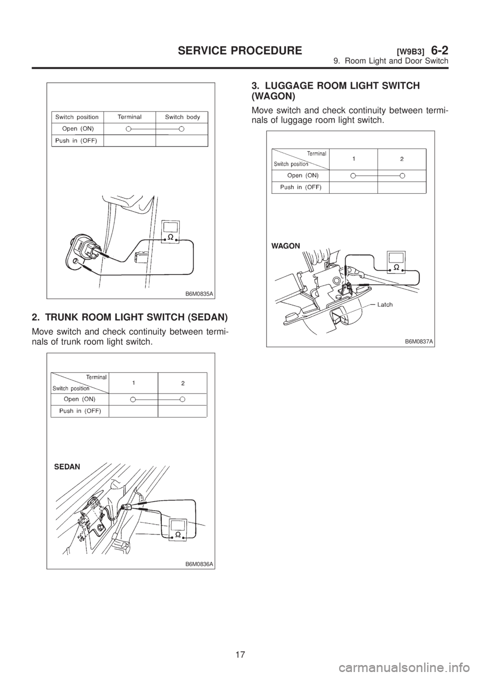
2. TRUNK ROOM LIGHT SWITCH (SEDAN)
Move switch and check continuity between termi-
nals of trunk room light switch.
B6M0836A
3. LUGGAGE ROOM LIGHT SWITCH
(WAGON)
Move switch and check continuity between termi-
nals of luggage room light switch.
B6M0837A
17
[W9B3]6-2SERVICE PROCEDURE
9. Room Light and Door Switch
Page 1245 of 1456
10. Spot Light
A: REMOVAL AND INSTALLATION
1. SPOT LIGHT AND SWITCH
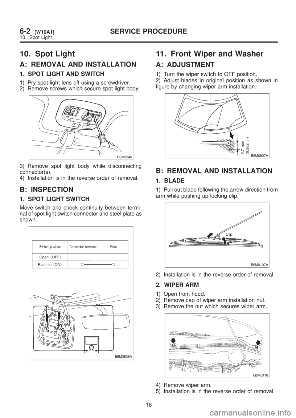
1) Pry spot light lens off using a screwdriver.
2) Remove screws which secure spot light body.
B6M0346
3) Remove spot light body while disconnecting
connector(s).
4) Installation is in the reverse order of removal.
B: INSPECTION
1. SPOT LIGHT SWITCH
Move switch and check continuity between termi-
nal of spot light switch connector and steel plate as
shown.
B6M0838A
11. Front Wiper and Washer
A: ADJUSTMENT
1) Turn the wiper switch to OFF position.
2) Adjust blades in original position as shown in
figure by changing wiper arm installation.
B6M0907A
B: REMOVAL AND INSTALLATION
1. BLADE
1) Pull out blade following the arrow direction from
arm while pushing up locking clip.
B6M0107A
2) Installation is in the reverse order of removal.
2. WIPER ARM
1) Open front hood.
2) Remove cap of wiper arm installation nut.
3) Remove the nut which secures wiper arm.
G6M0118
4) Remove wiper arm.
5) Installation is in the reverse order of removal.
18
6-2[W10A1]SERVICE PROCEDURE
10. Spot Light
Page 1246 of 1456
10. Spot Light
A: REMOVAL AND INSTALLATION
1. SPOT LIGHT AND SWITCH
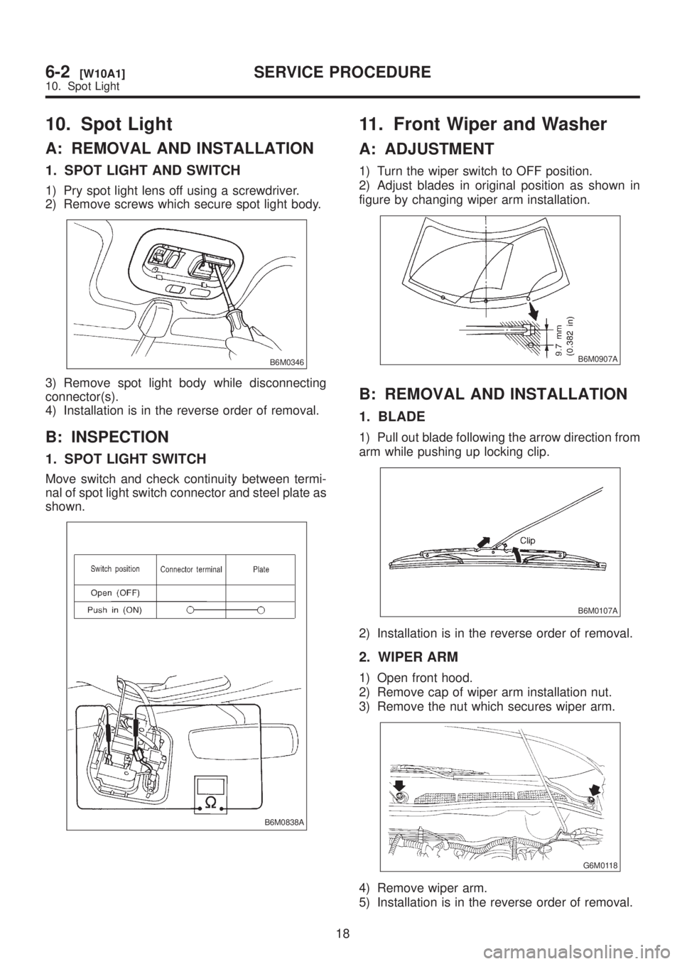
1) Pry spot light lens off using a screwdriver.
2) Remove screws which secure spot light body.
B6M0346
3) Remove spot light body while disconnecting
connector(s).
4) Installation is in the reverse order of removal.
B: INSPECTION
1. SPOT LIGHT SWITCH
Move switch and check continuity between termi-
nal of spot light switch connector and steel plate as
shown.
B6M0838A
11. Front Wiper and Washer
A: ADJUSTMENT
1) Turn the wiper switch to OFF position.
2) Adjust blades in original position as shown in
figure by changing wiper arm installation.
B6M0907A
B: REMOVAL AND INSTALLATION
1. BLADE
1) Pull out blade following the arrow direction from
arm while pushing up locking clip.
B6M0107A
2) Installation is in the reverse order of removal.
2. WIPER ARM
1) Open front hood.
2) Remove cap of wiper arm installation nut.
3) Remove the nut which secures wiper arm.
G6M0118
4) Remove wiper arm.
5) Installation is in the reverse order of removal.
18
6-2[W10A1]SERVICE PROCEDURE
10. Spot Light
Page 1256 of 1456
B: BULB REPLACEMENT
B6M0761C
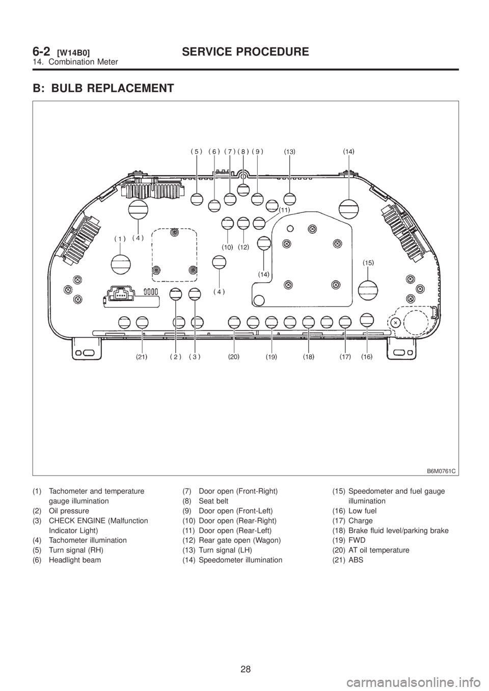
(1) Tachometer and temperature
gauge illumination
(2) Oil pressure
(3) CHECK ENGINE (Malfunction
Indicator Light)
(4) Tachometer illumination
(5) Turn signal (RH)
(6) Headlight beam(7) Door open (Front-Right)
(8) Seat belt
(9) Door open (Front-Left)
(10) Door open (Rear-Right)
(11) Door open (Rear-Left)
(12) Rear gate open (Wagon)
(13) Turn signal (LH)
(14) Speedometer illumination(15) Speedometer and fuel gauge
illumination
(16) Low fuel
(17) Charge
(18) Brake fluid level/parking brake
(19) FWD
(20) AT oil temperature
(21) ABS
28
6-2[W14B0]SERVICE PROCEDURE
14. Combination Meter
Page 1258 of 1456

16. Horn and Cigarette Lighter
A: REMOVAL AND INSTALLATION
1. HORN
1) Open the engine hood.
2) Disconnect connector of horn.
3) Remove the horn.
4) Installation is in the reverse order of removal.
Tightening torque:
18
±5 N´m (1.8±0.5 kg-m, 13.0±3.6 ft-lb)
CAUTION:
After installing horn, connect connector, fit
firmly wiring harness to prevent from discon-
necting due to vibration.
B6M0349
2. HORN SWITCH (HORN PAD)
1) Remove screw which secures horn switch
(steering pad) to the base of steering wheel.
B6M0124
2) Remove horn switch (steering pad) from steer-
ing wheel while disconnecting connector.
3) Installation is in the reverse order of removal.
3. CIGARETTE LIGHTER
1) Remove center panel from instrument panel.
2) Disconnect connector from cigarette lighter.
3) Turn illumination socket 45É counterclockwise
and remove it.4) Loosen nut, and then remove cigarette lighter
body.
B6M0350A
5) Installation is in the reverse order of removal.
CAUTION:
IAlign socket with cutout portion of instru-
ment panel during installation.
IIn case of replacing cigarette lighter, use
genuine part only and always replace both plug
and socket combination.
B: INSPECTION
1. HORN SWITCH
Ensure that horn switch is free from the following
defects:
(1) Burned or shorted contacts
(2) Broken or weak spring
(3) Damaged harness
(4) Worn or corroded mating surface of horn plate
2. HORN RELAY
Check continuity between terminals as indicated in
table, when connecting the battery to terminals No.
1 and No. 2.
When current flows. Between termi-
nals No. 2 and
No. 3Continuity
exists.
When current does not
flow.Between termi-
nals No. 2 and
No. 3Continuity does
not exist.
Between termi-
nals No. 1 and
No. 2Continuity
exists.
B6M0126A
30
6-2[W16A1]SERVICE PROCEDURE
16. Horn and Cigarette Lighter
Page 1259 of 1456
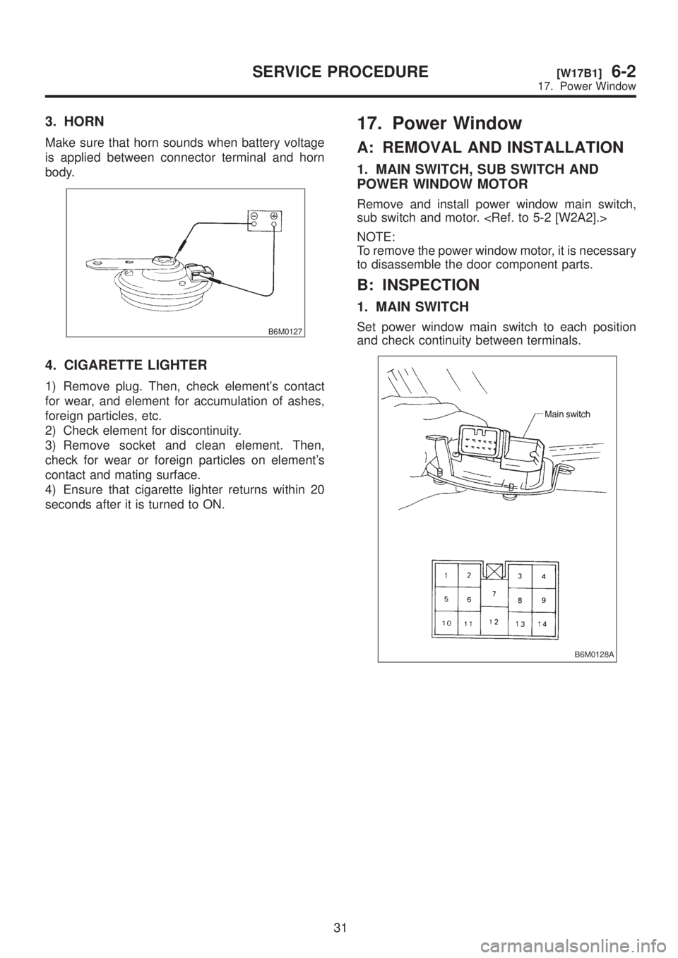
3. HORN
Make sure that horn sounds when battery voltage
is applied between connector terminal and horn
body.
B6M0127
4. CIGARETTE LIGHTER
1) Remove plug. Then, check element's contact
for wear, and element for accumulation of ashes,
foreign particles, etc.
2) Check element for discontinuity.
3) Remove socket and clean element. Then,
check for wear or foreign particles on element's
contact and mating surface.
4) Ensure that cigarette lighter returns within 20
seconds after it is turned to ON.
17. Power Window
A: REMOVAL AND INSTALLATION
1. MAIN SWITCH, SUB SWITCH AND
POWER WINDOW MOTOR
Remove and install power window main switch,
sub switch and motor.
NOTE:
To remove the power window motor, it is necessary
to disassemble the door component parts.
B: INSPECTION
1. MAIN SWITCH
Set power window main switch to each position
and check continuity between terminals.
B6M0128A
31
[W17B1]6-2SERVICE PROCEDURE
17. Power Window
Page 1260 of 1456
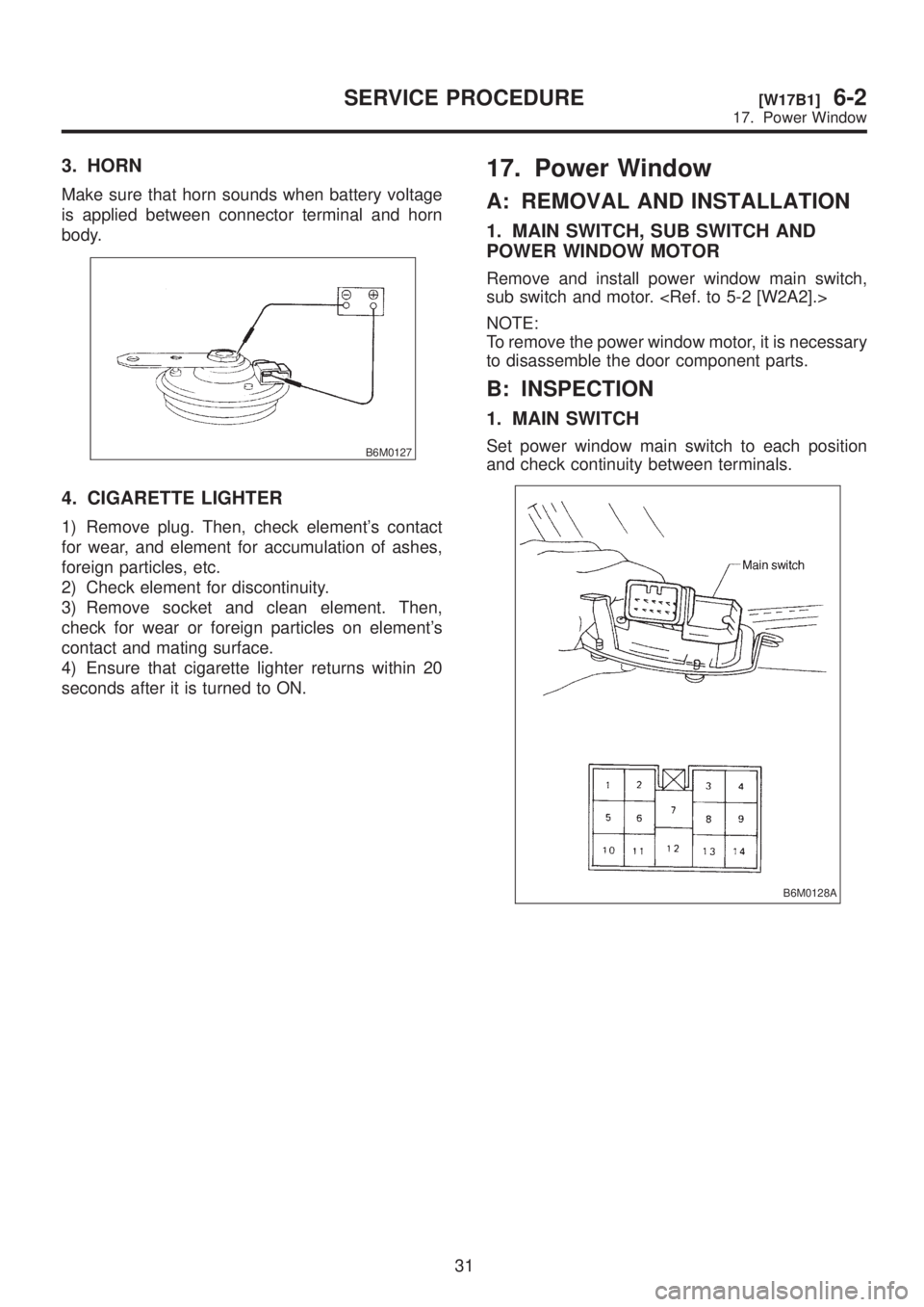
3. HORN
Make sure that horn sounds when battery voltage
is applied between connector terminal and horn
body.
B6M0127
4. CIGARETTE LIGHTER
1) Remove plug. Then, check element's contact
for wear, and element for accumulation of ashes,
foreign particles, etc.
2) Check element for discontinuity.
3) Remove socket and clean element. Then,
check for wear or foreign particles on element's
contact and mating surface.
4) Ensure that cigarette lighter returns within 20
seconds after it is turned to ON.
17. Power Window
A: REMOVAL AND INSTALLATION
1. MAIN SWITCH, SUB SWITCH AND
POWER WINDOW MOTOR
Remove and install power window main switch,
sub switch and motor.
NOTE:
To remove the power window motor, it is necessary
to disassemble the door component parts.
B: INSPECTION
1. MAIN SWITCH
Set power window main switch to each position
and check continuity between terminals.
B6M0128A
31
[W17B1]6-2SERVICE PROCEDURE
17. Power Window
Page 1267 of 1456
![SUBARU LEGACY 1999 Service Repair Manual 20. Sunroof
A: REMOVAL AND INSTALLATION
1. SUNROOF AND SUNROOF MOTOR
<Ref. to 5-1 [W1600].> as for removal and instal-
lation of sunroof system.
2. SUNROOF SWITCH
NOTE:
The sunroof switch is installed](/img/17/57435/w960_57435-1266.png "SUBARU LEGACY 1999 Service Repair Manual 20. Sunroof
A: REMOVAL AND INSTALLATION
1. SUNROOF AND SUNROOF MOTOR
<Ref. to 5-1 [W1600].> as for removal and instal-
lation of sunroof system.
2. SUNROOF SWITCH
NOTE:
The sunroof switch is installed")
20. Sunroof
A: REMOVAL AND INSTALLATION
1. SUNROOF AND SUNROOF MOTOR
lation of sunroof system.
2. SUNROOF SWITCH
NOTE:
The sunroof switch is installed in spot light body.
1) Pry spot light lens off using a screwdriver.
2) Remove screws which secure spot light body.
3) Remove spot light body while disconnecting
connectors.
4) Remove screw which secures sunroof switch,
and then remove sunroof switch.
B6M0141A
5) Installation is in the reverse order of removal.
B: INSPECTION
1. SUNROOF SWITCH
Set sunroof switch to each position and check con-
tinuity between terminals as indicated in table
below:
B6M0142A
B6M0861A
37
[W20B1]6-2SERVICE PROCEDURE
20. Sunroof
Page 1269 of 1456
21. Radio, Speaker and
Antenna
A: REMOVAL AND INSTALLATION
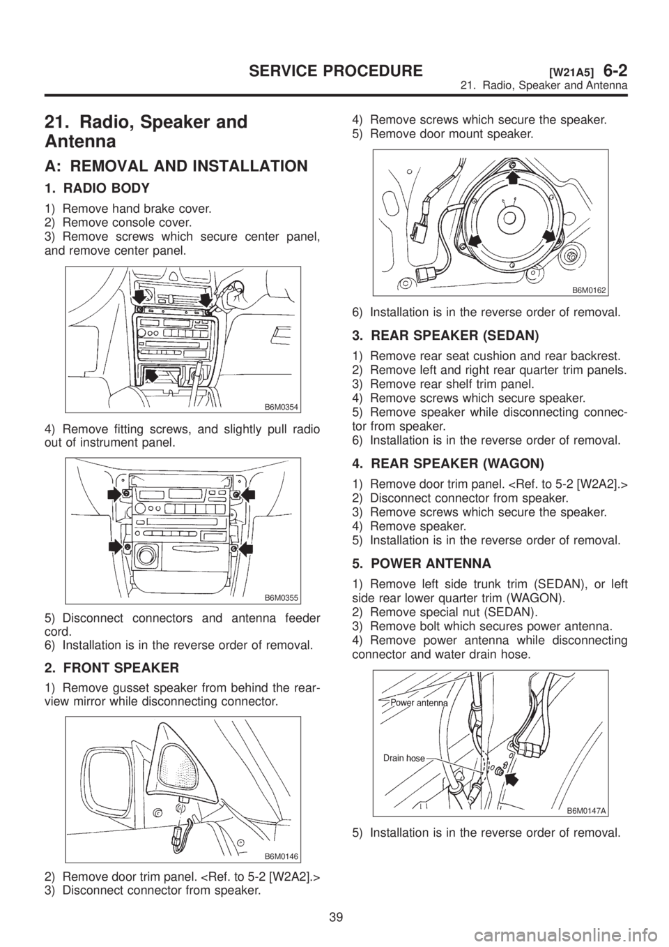
1. RADIO BODY
1) Remove hand brake cover.
2) Remove console cover.
3) Remove screws which secure center panel,
and remove center panel.
B6M0354
4) Remove fitting screws, and slightly pull radio
out of instrument panel.
B6M0355
5) Disconnect connectors and antenna feeder
cord.
6) Installation is in the reverse order of removal.
2. FRONT SPEAKER
1) Remove gusset speaker from behind the rear-
view mirror while disconnecting connector.
B6M0146
2) Remove door trim panel.
3) Disconnect connector from speaker.4) Remove screws which secure the speaker.
5) Remove door mount speaker.
B6M0162
6) Installation is in the reverse order of removal.
3. REAR SPEAKER (SEDAN)
1) Remove rear seat cushion and rear backrest.
2) Remove left and right rear quarter trim panels.
3) Remove rear shelf trim panel.
4) Remove screws which secure speaker.
5) Remove speaker while disconnecting connec-
tor from speaker.
6) Installation is in the reverse order of removal.
4. REAR SPEAKER (WAGON)
1) Remove door trim panel.
2) Disconnect connector from speaker.
3) Remove screws which secure the speaker.
4) Remove speaker.
5) Installation is in the reverse order of removal.
5. POWER ANTENNA
1) Remove left side trunk trim (SEDAN), or left
side rear lower quarter trim (WAGON).
2) Remove special nut (SEDAN).
3) Remove bolt which secures power antenna.
4) Remove power antenna while disconnecting
connector and water drain hose.
B6M0147A
5) Installation is in the reverse order of removal.
39
[W21A5]6-2SERVICE PROCEDURE
21. Radio, Speaker and Antenna
Page 1273 of 1456
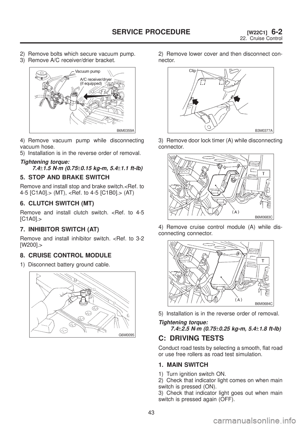
2) Remove bolts which secure vacuum pump.
3) Remove A/C receiver/drier bracket.
B6M0359A
4) Remove vacuum pump while disconnecting
vacuum hose.
5) Installation is in the reverse order of removal.
Tightening torque:
7.4
±1.5 N´m (0.75±0.15 kg-m, 5.4±1.1 ft-lb)
5. STOP AND BRAKE SWITCH
Remove and install stop and brake switch.
6. CLUTCH SWITCH (MT)
Remove and install clutch switch.
7. INHIBITOR SWITCH (AT)
Remove and install inhibitor switch.
8. CRUISE CONTROL MODULE
1) Disconnect battery ground cable.
G6M0095
2) Remove lower cover and then disconnect con-
nector.
B3M0377A
3) Remove door lock timer (A) while disconnecting
connector.
B6M0683C
4) Remove cruise control module (A) while dis-
connecting connector.
B6M0684C
5) Installation is in the reverse order of removal.
Tightening torque:
7.4
±2.5 N´m (0.75±0.25 kg-m, 5.4±1.8 ft-lb)
C: DRIVING TESTS
Conduct road tests by selecting a smooth, flat road
or use free rollers as road test simulation.
1. MAIN SWITCH
1) Turn ignition switch ON.
2) Check that indicator light comes on when main
switch is pressed (ON).
3) Check that indicator light goes out when main
switch is pressed again (OFF).
43
[W22C1]6-2SERVICE PROCEDURE
22. Cruise Control