Rear differential SUBARU LEGACY 1999 Service User Guide
[x] Cancel search | Manufacturer: SUBARU, Model Year: 1999, Model line: LEGACY, Model: SUBARU LEGACY 1999Pages: 1456, PDF Size: 59.93 MB
Page 490 of 1456
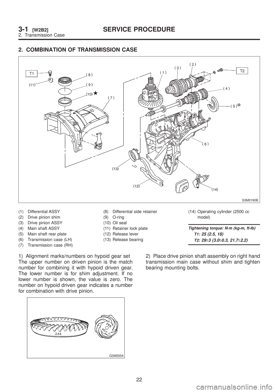
2. COMBINATION OF TRANSMISSION CASE
S3M0190B
(1) Differential ASSY
(2) Drive pinion shim
(3) Drive pinion ASSY
(4) Main shaft ASSY
(5) Main shaft rear plate
(6) Transmission case (LH)
(7) Transmission case (RH)(8) Differential side retainer
(9) O-ring
(10) Oil seal
(11) Retainer lock plate
(12) Release lever
(13) Release bearing(14) Operating cylinder (2500 cc
model)
Tightening torque: N´m (kg-m, ft-lb)
T1:
25 (2.5, 18)
T2:29±3 (3.0±0.3, 21.7±2.2)
1) Alignment marks/numbers on hypoid gear set
The upper number on driven pinion is the match
number for combining it with hypoid driven gear.
The lower number is for shim adjustment. If no
lower number is shown, the value is zero. The
number on hypoid driven gear indicates a number
for combination with drive pinion.
G3M0554
2) Place drive pinion shaft assembly on right hand
transmission main case without shim and tighten
bearing mounting bolts.
22
3-1[W2B2]SERVICE PROCEDURE
2. Transmission Case
Page 501 of 1456
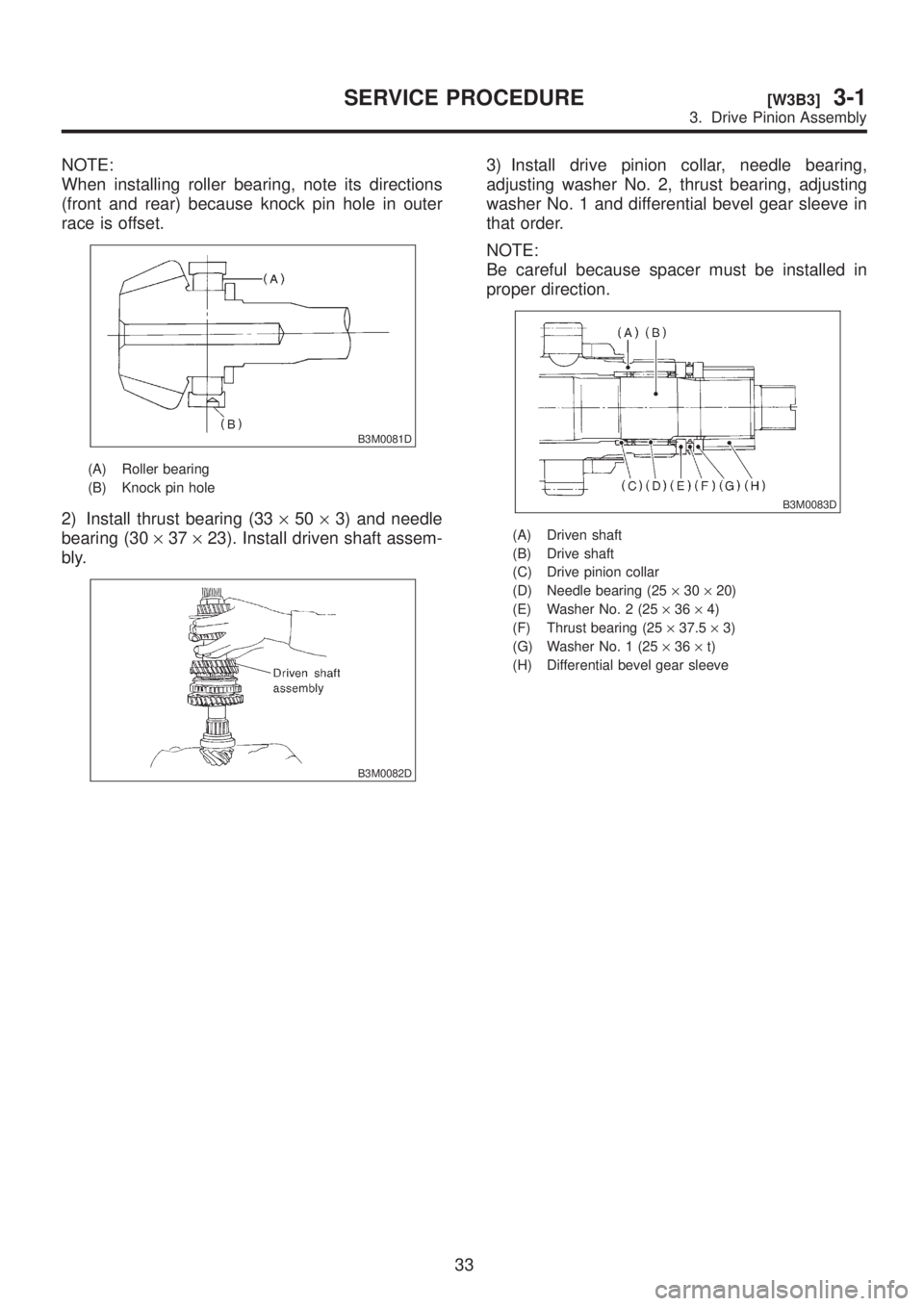
NOTE:
When installing roller bearing, note its directions
(front and rear) because knock pin hole in outer
race is offset.
B3M0081D
(A) Roller bearing
(B) Knock pin hole
2) Install thrust bearing (33´50´3) and needle
bearing (30´37´23). Install driven shaft assem-
bly.
B3M0082D
3) Install drive pinion collar, needle bearing,
adjusting washer No. 2, thrust bearing, adjusting
washer No. 1 and differential bevel gear sleeve in
that order.
NOTE:
Be careful because spacer must be installed in
proper direction.
B3M0083D
(A) Driven shaft
(B) Drive shaft
(C) Drive pinion collar
(D) Needle bearing (25´30´20)
(E) Washer No. 2 (25´36´4)
(F) Thrust bearing (25´37.5´3)
(G) Washer No. 1 (25´36´t)
(H) Differential bevel gear sleeve
33
[W3B3]3-1SERVICE PROCEDURE
3. Drive Pinion Assembly
Page 527 of 1456
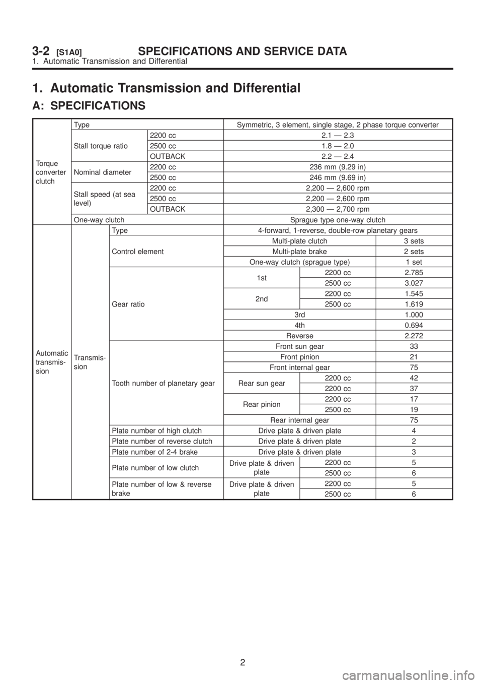
1. Automatic Transmission and Differential
A: SPECIFICATIONS
Torque
converter
clutchType Symmetric, 3 element, single stage, 2 phase torque converter
Stall torque ratio2200 cc 2.1 Ð 2.3
2500 cc 1.8 Ð 2.0
OUTBACK 2.2 Ð 2.4
Nominal diameter2200 cc 236 mm (9.29 in)
2500 cc 246 mm (9.69 in)
Stall speed (at sea
level)2200 cc 2,200 Ð 2,600 rpm
2500 cc 2,200 Ð 2,600 rpm
OUTBACK 2,300 Ð 2,700 rpm
One-way clutch Sprague type one-way clutch
Automatic
transmis-
sionTransmis-
sionType 4-forward, 1-reverse, double-row planetary gears
Control elementMulti-plate clutch 3 sets
Multi-plate brake 2 sets
One-way clutch (sprague type) 1 set
Gear ratio1st2200 cc 2.785
2500 cc 3.027
2nd2200 cc 1.545
2500 cc 1.619
3rd 1.000
4th 0.694
Reverse 2.272
Tooth number of planetary gearFront sun gear 33
Front pinion 21
Front internal gear 75
Rear sun gear2200 cc 42
2200 cc 37
Rear pinion2200 cc 17
2500 cc 19
Rear internal gear 75
Plate number of high clutch Drive plate & driven plate 4
Plate number of reverse clutch Drive plate & driven plate 2
Plate number of 2-4 brake Drive plate & driven plate 3
Plate number of low clutchDrive plate & driven
plate2200 cc 5
2500 cc 6
Plate number of low & reverse
brakeDrive plate & driven
plate2200 cc 5
2500 cc 6
2
3-2[S1A0]SPECIFICATIONS AND SERVICE DATA
1. Automatic Transmission and Differential
Page 536 of 1456
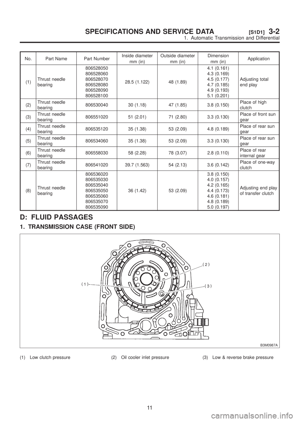
No. Part Name Part NumberInside diameter
mm (in)Outside diameter
mm (in)Dimension
mm (in)Application
(1)Thrust needle
bearing806528050
806528060
806528070
806528080
806528090
80652810028.5 (1.122) 48 (1.89)4.1 (0.161)
4.3 (0.169)
4.5 (0.177)
4.7 (0.185)
4.9 (0.193)
5.1 (0.201)Adjusting total
end play
(2)Thrust needle
bearing806530040 30 (1.18) 47 (1.85) 3.8 (0.150)Place of high
clutch
(3)Thrust needle
bearing806551020 51 (2.01) 71 (2.80) 3.3 (0.130)Place of front sun
gear
(4)Thrust needle
bearing806535120 35 (1.38) 53 (2.09) 4.8 (0.189)Place of rear sun
gear
(5)Thrust needle
bearing806534060 35 (1.38) 53 (2.09) 3.3 (0.130)Place of rear sun
gear
(6)Thrust needle
bearing806558030 58 (2.28) 78 (3.07) 2.8 (0.110)Place of rear
internal gear
(7)Thrust needle
bearing806541020 39.7 (1.563) 54 (2.13) 3.6 (0.142)Place of one-way
clutch
(8)Thrust needle
bearing806536020
806535030
806535040
806535050
806535060
806535070
80653509036 (1.42) 53 (2.09)3.8 (0.150)
4.0 (0.157)
4.2 (0.165)
4.4 (0.173)
4.6 (0.181)
4.8 (0.189)
5.0 (0.197)Adjusting end play
of transfer clutch
D: FLUID PASSAGES
1. TRANSMISSION CASE (FRONT SIDE)
B3M0987A
(1) Low clutch pressure (2) Oil cooler inlet pressure (3) Low & reverse brake pressure
11
[S1D1]3-2SPECIFICATIONS AND SERVICE DATA
1. Automatic Transmission and Differential
Page 537 of 1456
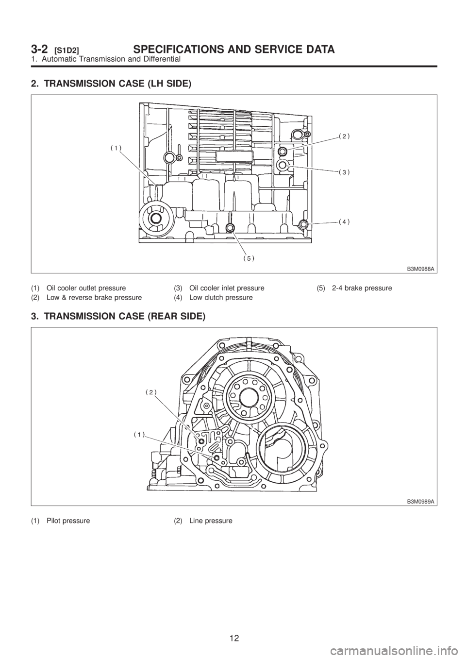
2. TRANSMISSION CASE (LH SIDE)
B3M0988A
(1) Oil cooler outlet pressure
(2) Low & reverse brake pressure(3) Oil cooler inlet pressure
(4) Low clutch pressure(5) 2-4 brake pressure
3. TRANSMISSION CASE (REAR SIDE)
B3M0989A
(1) Pilot pressure (2) Line pressure
12
3-2[S1D2]SPECIFICATIONS AND SERVICE DATA
1. Automatic Transmission and Differential
Page 554 of 1456
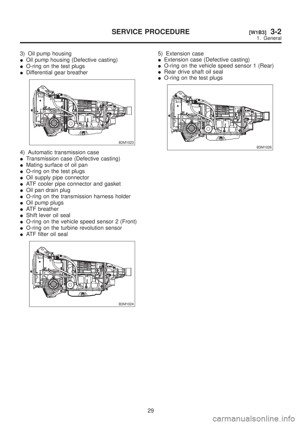
3) Oil pump housing
IOil pump housing (Defective casting)
IO-ring on the test plugs
IDifferential gear breather
B3M1023
4) Automatic transmission case
ITransmission case (Defective casting)
IMating surface of oil pan
IO-ring on the test plugs
IOil supply pipe connector
IATF cooler pipe connector and gasket
IOil pan drain plug
IO-ring on the transmission harness holder
IOil pump plugs
IATF breather
IShift lever oil seal
IO-ring on the vehicle speed sensor 2 (Front)
IO-ring on the turbine revolution sensor
IATF filter oil seal
B3M1024
5) Extension case
IExtension case (Defective casting)
IO-ring on the vehicle speed sensor 1 (Rear)
IRear drive shaft oil seal
IO-ring on the test plugs
B3M1026
29
[W1B3]3-2SERVICE PROCEDURE
1. General
Page 563 of 1456
![SUBARU LEGACY 1999 Service User Guide 5. Duty Solenoid C and
Transfer Valve Body
A: REMOVAL
1) Remove air intake duct and chamber. (Except
2200 cc California spec. vehicles)
<Ref. to 2-7 [W1A0].>
S6M0007
2) Remove air intake duct and clea](/img/17/57435/w960_57435-562.png "SUBARU LEGACY 1999 Service User Guide 5. Duty Solenoid C and
Transfer Valve Body
A: REMOVAL
1) Remove air intake duct and chamber. (Except
2200 cc California spec. vehicles)
<Ref. to 2-7 [W1A0].>
S6M0007
2) Remove air intake duct and clea")
5. Duty Solenoid C and
Transfer Valve Body
A: REMOVAL
1) Remove air intake duct and chamber. (Except
2200 cc California spec. vehicles)
S6M0007
2) Remove air intake duct and cleaner case.
(2200 cc California spec. vehicles)
B2M2320
3) Remove pitching stopper.
B3M1042
4) Raise vehicle and drain ATF.
B3M1036A
5) Remove front exhaust pipe and center exhaust
pipe.
Disconnect oxygen sensor connector, and remove
exhaust pipe.
G3M0305
6) Remove propeller shaft.
NOTE:
Before removing propeller shaft, scribe matching
marks on propeller shaft and rear differential cou-
pling.
G3M0782
37
[W5A0]3-2SERVICE PROCEDURE
5. Duty Solenoid C and Transfer Valve Body
Page 565 of 1456
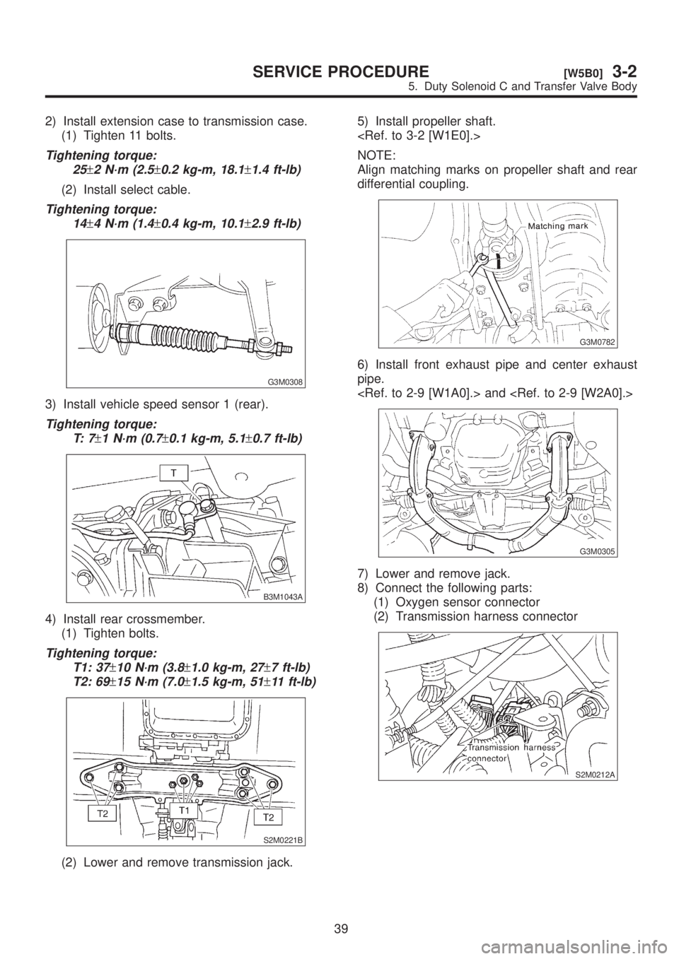
2) Install extension case to transmission case.
(1) Tighten 11 bolts.
Tightening torque:
25
±2 N´m (2.5±0.2 kg-m, 18.1±1.4 ft-lb)
(2) Install select cable.
Tightening torque:
14
±4 N´m (1.4±0.4 kg-m, 10.1±2.9 ft-lb)
G3M0308
3) Install vehicle speed sensor 1 (rear).
Tightening torque:
T: 7
±1 N´m (0.7±0.1 kg-m, 5.1±0.7 ft-lb)
B3M1043A
4) Install rear crossmember.
(1) Tighten bolts.
Tightening torque:
T1: 37
±10 N´m (3.8±1.0 kg-m, 27±7 ft-lb)
T2: 69
±15 N´m (7.0±1.5 kg-m, 51±11 ft-lb)
S2M0221B
(2) Lower and remove transmission jack.5) Install propeller shaft.
NOTE:
Align matching marks on propeller shaft and rear
differential coupling.
G3M0782
6) Install front exhaust pipe and center exhaust
pipe.
G3M0305
7) Lower and remove jack.
8) Connect the following parts:
(1) Oxygen sensor connector
(2) Transmission harness connector
S2M0212A
39
[W5B0]3-2SERVICE PROCEDURE
5. Duty Solenoid C and Transfer Valve Body
Page 583 of 1456
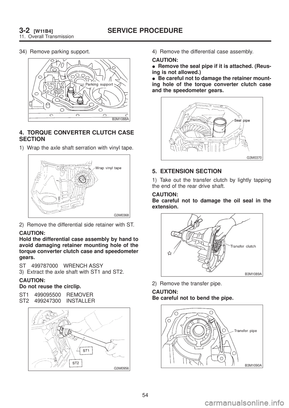
34) Remove parking support.
B3M1088A
4. TORQUE CONVERTER CLUTCH CASE
SECTION
1) Wrap the axle shaft serration with vinyl tape.
G3M0368
2) Remove the differential side retainer with ST.
CAUTION:
Hold the differential case assembly by hand to
avoid damaging retainer mounting hole of the
torque converter clutch case and speedometer
gears.
ST 499787000 WRENCH ASSY
3) Extract the axle shaft with ST1 and ST2.
CAUTION:
Do not reuse the circlip.
ST1 499095500 REMOVER
ST2 499247300 INSTALLER
G3M0956
4) Remove the differential case assembly.
CAUTION:
IRemove the seal pipe if it is attached. (Reus-
ing is not allowed.)
IBe careful not to damage the retainer mount-
ing hole of the torque converter clutch case
and the speedometer gears.
G3M0370
5. EXTENSION SECTION
1) Take out the transfer clutch by lightly tapping
the end of the rear drive shaft.
CAUTION:
Be careful not to damage the oil seal in the
extension.
B3M1089A
2) Remove the transfer pipe.
CAUTION:
Be careful not to bend the pipe.
B3M1090A
54
3-2[W11B4]SERVICE PROCEDURE
11. Overall Transmission
Page 652 of 1456
2. Rear Differential
A: SPECIFICATIONS
Type of gearHypoid
MT AT
2200 cc 2500 cc 2200 cc 2500 cc
Gear ratio (Number of gear teeth) 3.900 (39/10) 4.111 (37/9) 4.111 (37/9) 4.444 (40/9)
Oil capacity 0.8(0.8 US qt, 0.7 Imp qt)
Rear differential gear oil GL-5
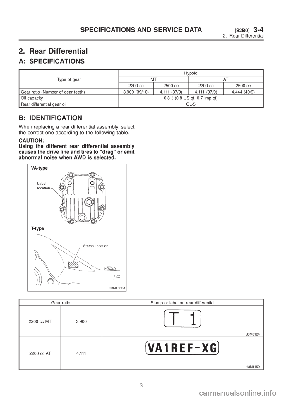
B: IDENTIFICATION
When replacing a rear differential assembly, select
the correct one according to the following table.
CAUTION:
Using the different rear differential assembly
causes the drive line and tires to ªdragº or emit
abnormal noise when AWD is selected.
H3M1662A
Gear ratio Stamp or label on rear differential
2200 cc MT 3.900
B3M0124
2200 cc AT 4.111
H3M1159
3
[S2B0]3-4SPECIFICATIONS AND SERVICE DATA
2. Rear Differential