checking oil SUBARU LEGACY 1999 Service User Guide
[x] Cancel search | Manufacturer: SUBARU, Model Year: 1999, Model line: LEGACY, Model: SUBARU LEGACY 1999Pages: 1456, PDF Size: 59.93 MB
Page 827 of 1456
![SUBARU LEGACY 1999 Service User Guide 5. Control Valve (Power Steering Gearbox) [LHD model]
A: CHECKING OIL LEAKING POINTS
B4M1132A
(1) Power cylinder
(2) Cylinder
(3) Rack piston
(4) Rack axle
(5) Input shaft(6) Torsion bar
(7) Valve hou](/img/17/57435/w960_57435-826.png "SUBARU LEGACY 1999 Service User Guide 5. Control Valve (Power Steering Gearbox) [LHD model]
A: CHECKING OIL LEAKING POINTS
B4M1132A
(1) Power cylinder
(2) Cylinder
(3) Rack piston
(4) Rack axle
(5) Input shaft(6) Torsion bar
(7) Valve hou")
5. Control Valve (Power Steering Gearbox) [LHD model]
A: CHECKING OIL LEAKING POINTS
B4M1132A
(1) Power cylinder
(2) Cylinder
(3) Rack piston
(4) Rack axle
(5) Input shaft(6) Torsion bar
(7) Valve housing
(8) Valve body
(9) Control valve
(10) Pipe B(11) Pipe A
(12) Pinion
(13) Pinion axle
1. OIL LEAKING POINTS
1) If leak point is other than a, b, c, or d, perform
check step 5) in ªOIL LEAK CHECK PROCEDURE
AND REPLACEMENT PARTSº before dismounting
gearbox from vehicle.
gearbox is dismounted without confirming where
the leak is, it must be mounted again to locate the
leak point.
2) Even if the location of the leak can be easily
found by observing the leaking condition, it is nec-
essary to thoroughly remove the oil from the sus-
pected portion and turn the steering wheel from
lock to lock about 30 to 40 times with engine
running, then make comparison of the suspected
portion between immediately after and several
hours after this operation.
3) Before starting oil leak repair work, be sure to
clean the gearbox, hoses, pipes, and surrounding
parts. After completing repair work, clean these
areas again.
2. OIL LEAK CHECK PROCEDURE AND
REPLACEMENT PARTS
NOTE:
Parts requiring replacement are described in the
smallest unit of spare parts including damaged
parts and spare parts damaged. In actual disas-sembly work, accidental damage as well as inevi-
table damage to some related parts must be taken
into account, and spare parts for them must also
be prepared. However, it is essential to pinpoint the
cause of trouble, and limit the number of replace-
ment parts as much as possible.
1) Leakage from ªaº
The oil seal is damaged. Replace valve assembly
with a new one.
2) Leakage from ªbº
The torsion bar O-ring is damaged. Replace valve
assembly with a new one.
3) Leakage from ªcº
The oil seal is damaged. Replace valve assembly
with a new one.
4) Leakage from ªdº
The pipe is damaged. Replace the faulty pipe or
O-ring.
5) If leak is other than a, b, c, or d, and if oil is
leaking from the gearbox, move the right and left
boots toward tie-rod end side, respectively, with the
gearbox mounted to the vehicle, and remove oil
from the surrounding portions. Then, turn the steer-
ing wheel from lock to lock 30 to 40 times with the
engine running, then make comparison of the
leaked portion immediately after and several hours
after this operation.
35
[W5A2]4-3SERVICE PROCEDURE
5. Control Valve (Power Steering Gearbox) [LHD model]
Page 834 of 1456
![SUBARU LEGACY 1999 Service User Guide 6. Control Valve (Power Steering Gearbox) [RHD model]
A: CHECKING OIL LEAKING POINTS
B4M0668A
1. OIL LEAKING POINTS
1) If leak point is other than a, b, c, or d, perform
check step 5) in ªOIL LEAK CH](/img/17/57435/w960_57435-833.png "SUBARU LEGACY 1999 Service User Guide 6. Control Valve (Power Steering Gearbox) [RHD model]
A: CHECKING OIL LEAKING POINTS
B4M0668A
1. OIL LEAKING POINTS
1) If leak point is other than a, b, c, or d, perform
check step 5) in ªOIL LEAK CH")
6. Control Valve (Power Steering Gearbox) [RHD model]
A: CHECKING OIL LEAKING POINTS
B4M0668A
1. OIL LEAKING POINTS
1) If leak point is other than a, b, c, or d, perform
check step 5) in ªOIL LEAK CHECK PROCEDURE
AND REPLACEMENT PARTSº before dismounting
gearbox from vehicle.
gearbox is dismounted without confirming where
the leak is, it must be mounted again to locate the
leak point.
2) Even if the location of the leak can be easily
found by observing the leaking condition, it is nec-
essary to thoroughly remove the oil from the sus-
pected portion and turn the steering wheel from
lock to lock about 30 to 40 times with engine
running, then make comparison of the suspected
portion between immediately after and several
hours after this operation.
3) Before starting oil leak repair work, be sure to
clean the gearbox, hoses, pipes, and surrounding
parts. After completing repair work, clean these
areas again.
2. OIL LEAK CHECK PROCEDURE AND
REPLACEMENT PARTS
NOTE:
Parts requiring replacement are described in the
smallest unit of spare parts including damaged
parts and spare parts damaged. In actual disas-
sembly work, accidental damage as well as inevi-
table damage to some related parts must be taken
into account, and spare parts for them must also
be prepared. However, it is essential to pinpoint the
cause of trouble, and limit the number of replace-
ment parts as much as possible.
1) Leakage from ªaº
The oil seal is damaged. Replace valve assembly
with a new one.
2) Leakage from ªbº
The torsion bar O-ring is damaged. Replace valve
assembly with a new one.
3) Leakage from ªcº
The oil seal is damaged. Replace valve assembly
with a new one.
4) Leakage from ªdº
The pipe is damaged. Replace the faulty pipe or
O-ring.
5) If leak is other than a, b, c, or d, and if oil is
leaking from the gearbox, move the right and left
42
4-3[W6A0]SERVICE PROCEDURE
6. Control Valve (Power Steering Gearbox) [RHD model]
Page 860 of 1456
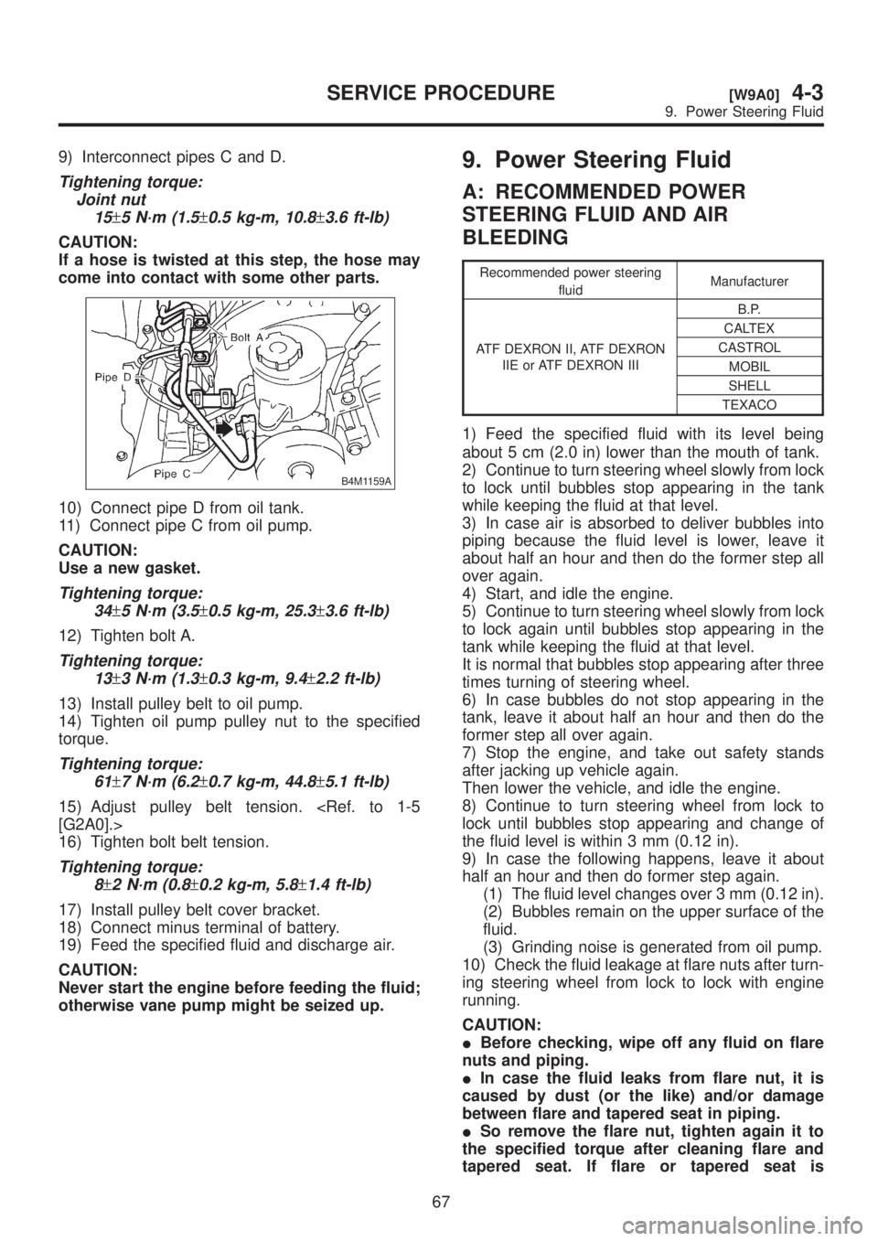
9) Interconnect pipes C and D.
Tightening torque:
Joint nut
15
±5 N´m (1.5±0.5 kg-m, 10.8±3.6 ft-lb)
CAUTION:
If a hose is twisted at this step, the hose may
come into contact with some other parts.
B4M1159A
10) Connect pipe D from oil tank.
11) Connect pipe C from oil pump.
CAUTION:
Use a new gasket.
Tightening torque:
34
±5 N´m (3.5±0.5 kg-m, 25.3±3.6 ft-lb)
12) Tighten bolt A.
Tightening torque:
13
±3 N´m (1.3±0.3 kg-m, 9.4±2.2 ft-lb)
13) Install pulley belt to oil pump.
14) Tighten oil pump pulley nut to the specified
torque.
Tightening torque:
61
±7 N´m (6.2±0.7 kg-m, 44.8±5.1 ft-lb)
15) Adjust pulley belt tension.
16) Tighten bolt belt tension.
Tightening torque:
8
±2 N´m (0.8±0.2 kg-m, 5.8±1.4 ft-lb)
17) Install pulley belt cover bracket.
18) Connect minus terminal of battery.
19) Feed the specified fluid and discharge air.
CAUTION:
Never start the engine before feeding the fluid;
otherwise vane pump might be seized up.
9. Power Steering Fluid
A: RECOMMENDED POWER
STEERING FLUID AND AIR
BLEEDING
Recommended power steering
fluidManufacturer
ATF DEXRON II, ATF DEXRON
IIE or ATF DEXRON IIIB.P.
CALTEX
CASTROL
MOBIL
SHELL
TEXACO
1) Feed the specified fluid with its level being
about 5 cm (2.0 in) lower than the mouth of tank.
2) Continue to turn steering wheel slowly from lock
to lock until bubbles stop appearing in the tank
while keeping the fluid at that level.
3) In case air is absorbed to deliver bubbles into
piping because the fluid level is lower, leave it
about half an hour and then do the former step all
over again.
4) Start, and idle the engine.
5) Continue to turn steering wheel slowly from lock
to lock again until bubbles stop appearing in the
tank while keeping the fluid at that level.
It is normal that bubbles stop appearing after three
times turning of steering wheel.
6) In case bubbles do not stop appearing in the
tank, leave it about half an hour and then do the
former step all over again.
7) Stop the engine, and take out safety stands
after jacking up vehicle again.
Then lower the vehicle, and idle the engine.
8) Continue to turn steering wheel from lock to
lock until bubbles stop appearing and change of
the fluid level is within 3 mm (0.12 in).
9) In case the following happens, leave it about
half an hour and then do former step again.
(1) The fluid level changes over 3 mm (0.12 in).
(2) Bubbles remain on the upper surface of the
fluid.
(3) Grinding noise is generated from oil pump.
10) Check the fluid leakage at flare nuts after turn-
ing steering wheel from lock to lock with engine
running.
CAUTION:
IBefore checking, wipe off any fluid on flare
nuts and piping.
IIn case the fluid leaks from flare nut, it is
caused by dust (or the like) and/or damage
between flare and tapered seat in piping.
ISo remove the flare nut, tighten again it to
the specified torque after cleaning flare and
tapered seat. If flare or tapered seat is
67
[W9A0]4-3SERVICE PROCEDURE
9. Power Steering Fluid
Page 861 of 1456
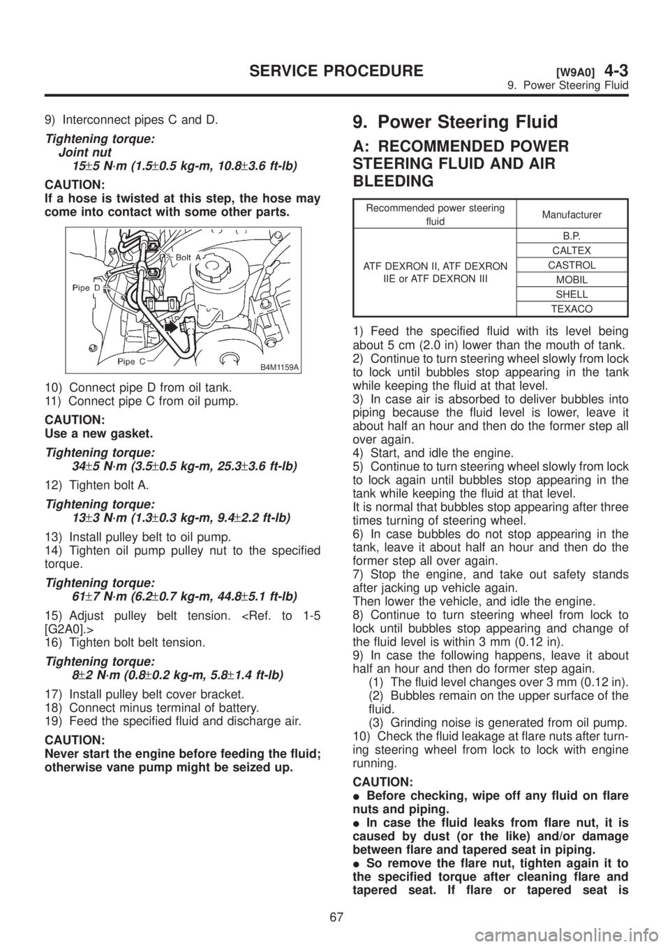
9) Interconnect pipes C and D.
Tightening torque:
Joint nut
15
±5 N´m (1.5±0.5 kg-m, 10.8±3.6 ft-lb)
CAUTION:
If a hose is twisted at this step, the hose may
come into contact with some other parts.
B4M1159A
10) Connect pipe D from oil tank.
11) Connect pipe C from oil pump.
CAUTION:
Use a new gasket.
Tightening torque:
34
±5 N´m (3.5±0.5 kg-m, 25.3±3.6 ft-lb)
12) Tighten bolt A.
Tightening torque:
13
±3 N´m (1.3±0.3 kg-m, 9.4±2.2 ft-lb)
13) Install pulley belt to oil pump.
14) Tighten oil pump pulley nut to the specified
torque.
Tightening torque:
61
±7 N´m (6.2±0.7 kg-m, 44.8±5.1 ft-lb)
15) Adjust pulley belt tension.
16) Tighten bolt belt tension.
Tightening torque:
8
±2 N´m (0.8±0.2 kg-m, 5.8±1.4 ft-lb)
17) Install pulley belt cover bracket.
18) Connect minus terminal of battery.
19) Feed the specified fluid and discharge air.
CAUTION:
Never start the engine before feeding the fluid;
otherwise vane pump might be seized up.
9. Power Steering Fluid
A: RECOMMENDED POWER
STEERING FLUID AND AIR
BLEEDING
Recommended power steering
fluidManufacturer
ATF DEXRON II, ATF DEXRON
IIE or ATF DEXRON IIIB.P.
CALTEX
CASTROL
MOBIL
SHELL
TEXACO
1) Feed the specified fluid with its level being
about 5 cm (2.0 in) lower than the mouth of tank.
2) Continue to turn steering wheel slowly from lock
to lock until bubbles stop appearing in the tank
while keeping the fluid at that level.
3) In case air is absorbed to deliver bubbles into
piping because the fluid level is lower, leave it
about half an hour and then do the former step all
over again.
4) Start, and idle the engine.
5) Continue to turn steering wheel slowly from lock
to lock again until bubbles stop appearing in the
tank while keeping the fluid at that level.
It is normal that bubbles stop appearing after three
times turning of steering wheel.
6) In case bubbles do not stop appearing in the
tank, leave it about half an hour and then do the
former step all over again.
7) Stop the engine, and take out safety stands
after jacking up vehicle again.
Then lower the vehicle, and idle the engine.
8) Continue to turn steering wheel from lock to
lock until bubbles stop appearing and change of
the fluid level is within 3 mm (0.12 in).
9) In case the following happens, leave it about
half an hour and then do former step again.
(1) The fluid level changes over 3 mm (0.12 in).
(2) Bubbles remain on the upper surface of the
fluid.
(3) Grinding noise is generated from oil pump.
10) Check the fluid leakage at flare nuts after turn-
ing steering wheel from lock to lock with engine
running.
CAUTION:
IBefore checking, wipe off any fluid on flare
nuts and piping.
IIn case the fluid leaks from flare nut, it is
caused by dust (or the like) and/or damage
between flare and tapered seat in piping.
ISo remove the flare nut, tighten again it to
the specified torque after cleaning flare and
tapered seat. If flare or tapered seat is
67
[W9A0]4-3SERVICE PROCEDURE
9. Power Steering Fluid
Page 995 of 1456
8. Leak Testing
A: INSPECTION
The following points should be kept in mind when
conducting a refrigerant leak test.
1) The A/C system to be tested must have an
adequate refrigerant charge to begin with.
2) The area where the leak test is conducted must
be free of wind and drafts, with still air being the
ideal condition.
3) The atmosphere where the leak test is con-
ducted must be free of refrigerant contamination.
4) Operate the A/C system for approx. 10 minutes,
then turn the engine off an begin the leak test.
5) Refrigerant gas is heavier than air, therefore
always hold the probe below the connection being
tested.
6) When checking for a leak along a length of
hose or tube, the leak detector probe must be
moved slowly, approx. 25 mm (1 in) per second
making sure probe does not come in contact with
the component being tested.
7) When checking for a leak at a certain point, the
leak detector probe must be held at that point for
at least 5 seconds.
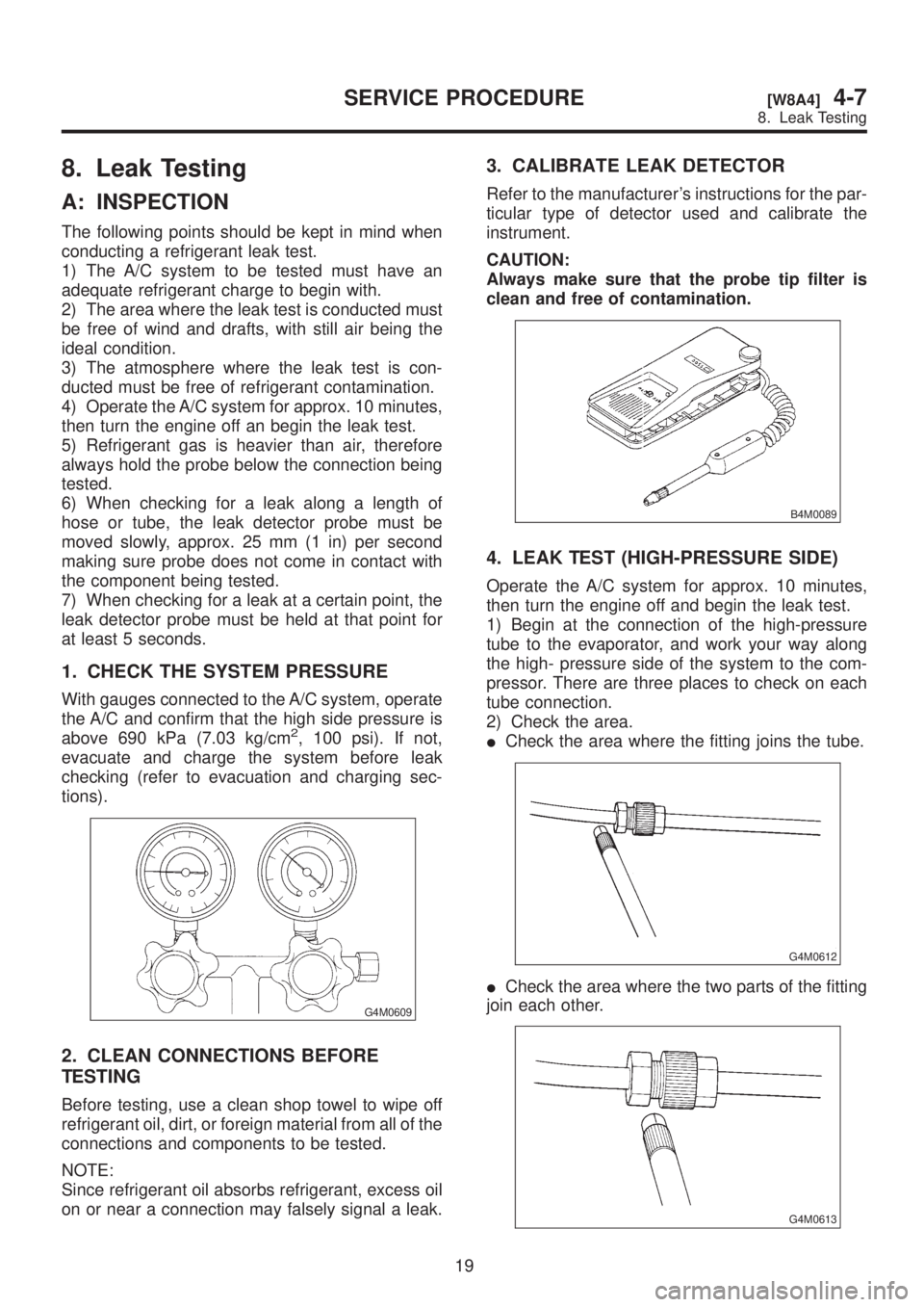
1. CHECK THE SYSTEM PRESSURE
With gauges connected to the A/C system, operate
the A/C and confirm that the high side pressure is
above 690 kPa (7.03 kg/cm
2, 100 psi). If not,
evacuate and charge the system before leak
checking (refer to evacuation and charging sec-
tions).
G4M0609
2. CLEAN CONNECTIONS BEFORE
TESTING
Before testing, use a clean shop towel to wipe off
refrigerant oil, dirt, or foreign material from all of the
connections and components to be tested.
NOTE:
Since refrigerant oil absorbs refrigerant, excess oil
on or near a connection may falsely signal a leak.
3. CALIBRATE LEAK DETECTOR
Refer to the manufacturer's instructions for the par-
ticular type of detector used and calibrate the
instrument.
CAUTION:
Always make sure that the probe tip filter is
clean and free of contamination.
B4M0089
4. LEAK TEST (HIGH-PRESSURE SIDE)
Operate the A/C system for approx. 10 minutes,
then turn the engine off and begin the leak test.
1) Begin at the connection of the high-pressure
tube to the evaporator, and work your way along
the high- pressure side of the system to the com-
pressor. There are three places to check on each
tube connection.
2) Check the area.
ICheck the area where the fitting joins the tube.
G4M0612
ICheck the area where the two parts of the fitting
join each other.
G4M0613
19
[W8A4]4-7SERVICE PROCEDURE
8. Leak Testing
Page 1231 of 1456
4. Headlight
A: ADJUSTMENT
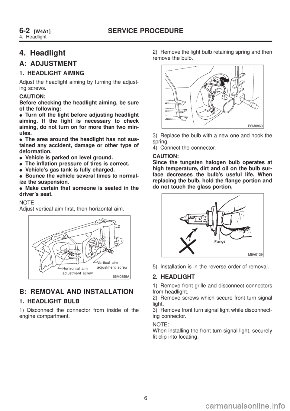
1. HEADLIGHT AIMING
Adjust the headlight aiming by turning the adjust-
ing screws.
CAUTION:
Before checking the headlight aiming, be sure
of the following:
ITurn off the light before adjusting headlight
aiming. If the light is necessary to check
aiming, do not turn on for more than two min-
utes.
IThe area around the headlight has not sus-
tained any accident, damage or other type of
deformation.
IVehicle is parked on level ground.
IThe inflation pressure of tires is correct.
IVehicle's gas tank is fully charged.
IBounce the vehicle several times to normal-
ize the suspension.
IMake certain that someone is seated in the
driver's seat.
NOTE:
Adjust vertical aim first, then horizontal aim.
B6M0859A
B: REMOVAL AND INSTALLATION
1. HEADLIGHT BULB
1) Disconnect the connector from inside of the
engine compartment.2) Remove the light bulb retaining spring and then
remove the bulb.
B6M0860
3) Replace the bulb with a new one and hook the
spring.
4) Connect the connector.
CAUTION:
Since the tungsten halogen bulb operates at
high temperature, dirt and oil on the bulb sur-
face decreases the bulb's useful life. When
replacing the bulb, hold the flange portion and
do not touch the glass portion.
M6A0139
5) Installation is in the reverse order of removal.
2. HEADLIGHT
1) Remove front grille and disconnect connectors
from headlight.
2) Remove screws which secure front turn signal
light.
3) Remove front turn signal light while disconnect-
ing connector.
NOTE:
When installing the front turn signal light, securely
fit clip into locating.
6
6-2[W4A1]SERVICE PROCEDURE
4. Headlight