oil filter SUBARU LEGACY 1999 Service Owner's Manual
[x] Cancel search | Manufacturer: SUBARU, Model Year: 1999, Model line: LEGACY, Model: SUBARU LEGACY 1999Pages: 1456, PDF Size: 59.93 MB
Page 227 of 1456
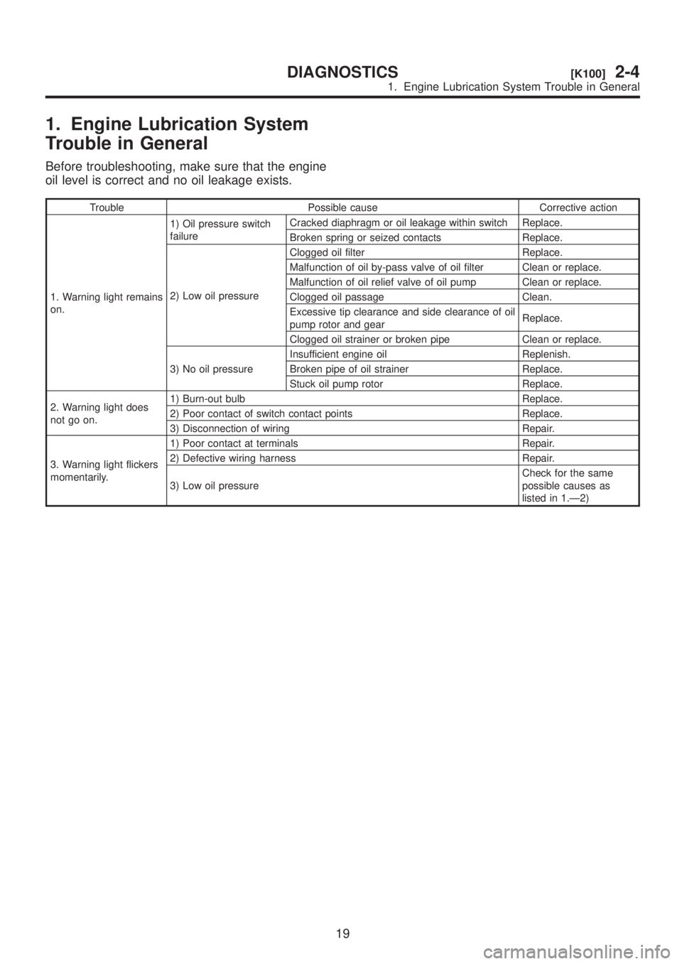
1. Engine Lubrication System
Trouble in General
Before troubleshooting, make sure that the engine
oil level is correct and no oil leakage exists.
Trouble Possible cause Corrective action
1. Warning light remains
on.1) Oil pressure switch
failureCracked diaphragm or oil leakage within switch Replace.
Broken spring or seized contacts Replace.
2) Low oil pressureClogged oil filter Replace.
Malfunction of oil by-pass valve of oil filter Clean or replace.
Malfunction of oil relief valve of oil pump Clean or replace.
Clogged oil passage Clean.
Excessive tip clearance and side clearance of oil
pump rotor and gearReplace.
Clogged oil strainer or broken pipe Clean or replace.
3) No oil pressureInsufficient engine oil Replenish.
Broken pipe of oil strainer Replace.
Stuck oil pump rotor Replace.
2. Warning light does
not go on.1) Burn-out bulb Replace.
2) Poor contact of switch contact points Replace.
3) Disconnection of wiring Repair.
3. Warning light flickers
momentarily.1) Poor contact at terminals Repair.
2) Defective wiring harness Repair.
3) Low oil pressureCheck for the same
possible causes as
listed in 1.Ð2)
19
[K100]2-4DIAGNOSTICS
1. Engine Lubrication System Trouble in General
Page 544 of 1456
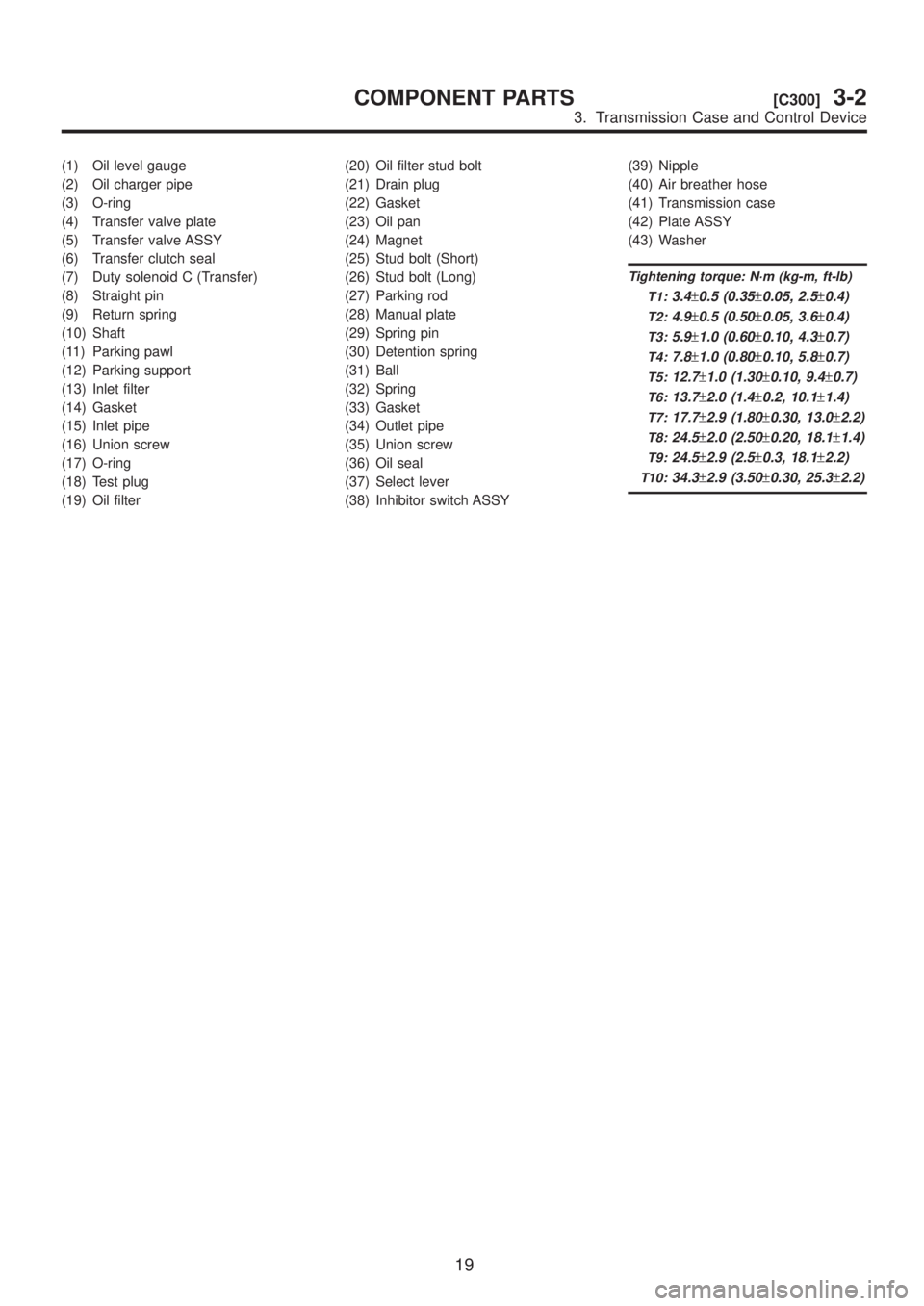
(1) Oil level gauge
(2) Oil charger pipe
(3) O-ring
(4) Transfer valve plate
(5) Transfer valve ASSY
(6) Transfer clutch seal
(7) Duty solenoid C (Transfer)
(8) Straight pin
(9) Return spring
(10) Shaft
(11) Parking pawl
(12) Parking support
(13) Inlet filter
(14) Gasket
(15) Inlet pipe
(16) Union screw
(17) O-ring
(18) Test plug
(19) Oil filter(20) Oil filter stud bolt
(21) Drain plug
(22) Gasket
(23) Oil pan
(24) Magnet
(25) Stud bolt (Short)
(26) Stud bolt (Long)
(27) Parking rod
(28) Manual plate
(29) Spring pin
(30) Detention spring
(31) Ball
(32) Spring
(33) Gasket
(34) Outlet pipe
(35) Union screw
(36) Oil seal
(37) Select lever
(38) Inhibitor switch ASSY(39) Nipple
(40) Air breather hose
(41) Transmission case
(42) Plate ASSY
(43) Washer
Tightening torque: N´m (kg-m, ft-lb)
T1:
3.4±0.5 (0.35±0.05, 2.5±0.4)
T2:4.9±0.5 (0.50±0.05, 3.6±0.4)
T3:5.9±1.0 (0.60±0.10, 4.3±0.7)
T4:7.8±1.0 (0.80±0.10, 5.8±0.7)
T5:12.7±1.0 (1.30±0.10, 9.4±0.7)
T6:13.7±2.0 (1.4±0.2, 10.1±1.4)
T7:17.7±2.9 (1.80±0.30, 13.0±2.2)
T8:24.5±2.0 (2.50±0.20, 18.1±1.4)
T9:24.5±2.9 (2.5±0.3, 18.1±2.2)
T10:34.3±2.9 (3.50±0.30, 25.3±2.2)
19
[C300]3-2COMPONENT PARTS
3. Transmission Case and Control Device
Page 545 of 1456
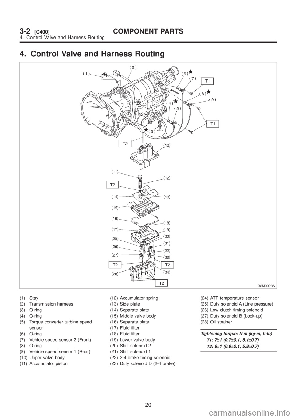
4. Control Valve and Harness Routing
B3M0928A
(1) Stay
(2) Transmission harness
(3) O-ring
(4) O-ring
(5) Torque converter turbine speed
sensor
(6) O-ring
(7) Vehicle speed sensor 2 (Front)
(8) O-ring
(9) Vehicle speed sensor 1 (Rear)
(10) Upper valve body
(11) Accumulator piston(12) Accumulator spring
(13) Side plate
(14) Separate plate
(15) Middle valve body
(16) Separate plate
(17) Fluid filter
(18) Fluid filter
(19) Lower valve body
(20) Shift solenoid 2
(21) Shift solenoid 1
(22) 2-4 brake timing solenoid
(23) Duty solenoid D (2-4 brake)(24) ATF temperature sensor
(25) Duty solenoid A (Line pressure)
(26) Low clutch timing solenoid
(27) Duty solenoid B (Lock-up)
(28) Oil strainer
Tightening torque: N´m (kg-m, ft-lb)
T1:
7±1 (0.7±0.1, 5.1±0.7)
T2:8±1 (0.8±0.1, 5.8±0.7)
20
3-2[C400]COMPONENT PARTS
4. Control Valve and Harness Routing
Page 554 of 1456
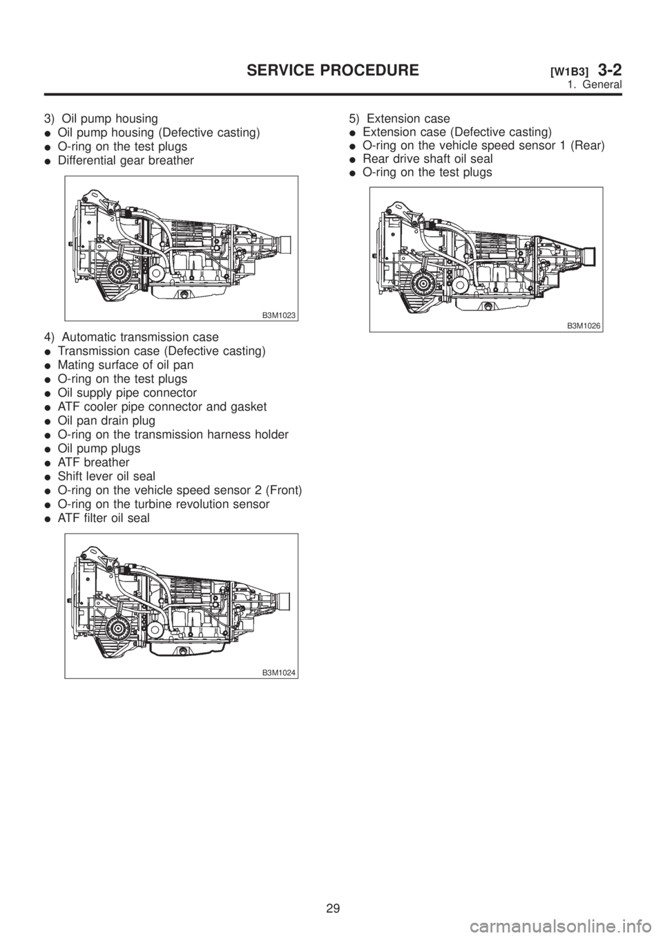
3) Oil pump housing
IOil pump housing (Defective casting)
IO-ring on the test plugs
IDifferential gear breather
B3M1023
4) Automatic transmission case
ITransmission case (Defective casting)
IMating surface of oil pan
IO-ring on the test plugs
IOil supply pipe connector
IATF cooler pipe connector and gasket
IOil pan drain plug
IO-ring on the transmission harness holder
IOil pump plugs
IATF breather
IShift lever oil seal
IO-ring on the vehicle speed sensor 2 (Front)
IO-ring on the turbine revolution sensor
IATF filter oil seal
B3M1024
5) Extension case
IExtension case (Defective casting)
IO-ring on the vehicle speed sensor 1 (Rear)
IRear drive shaft oil seal
IO-ring on the test plugs
B3M1026
29
[W1B3]3-2SERVICE PROCEDURE
1. General
Page 582 of 1456
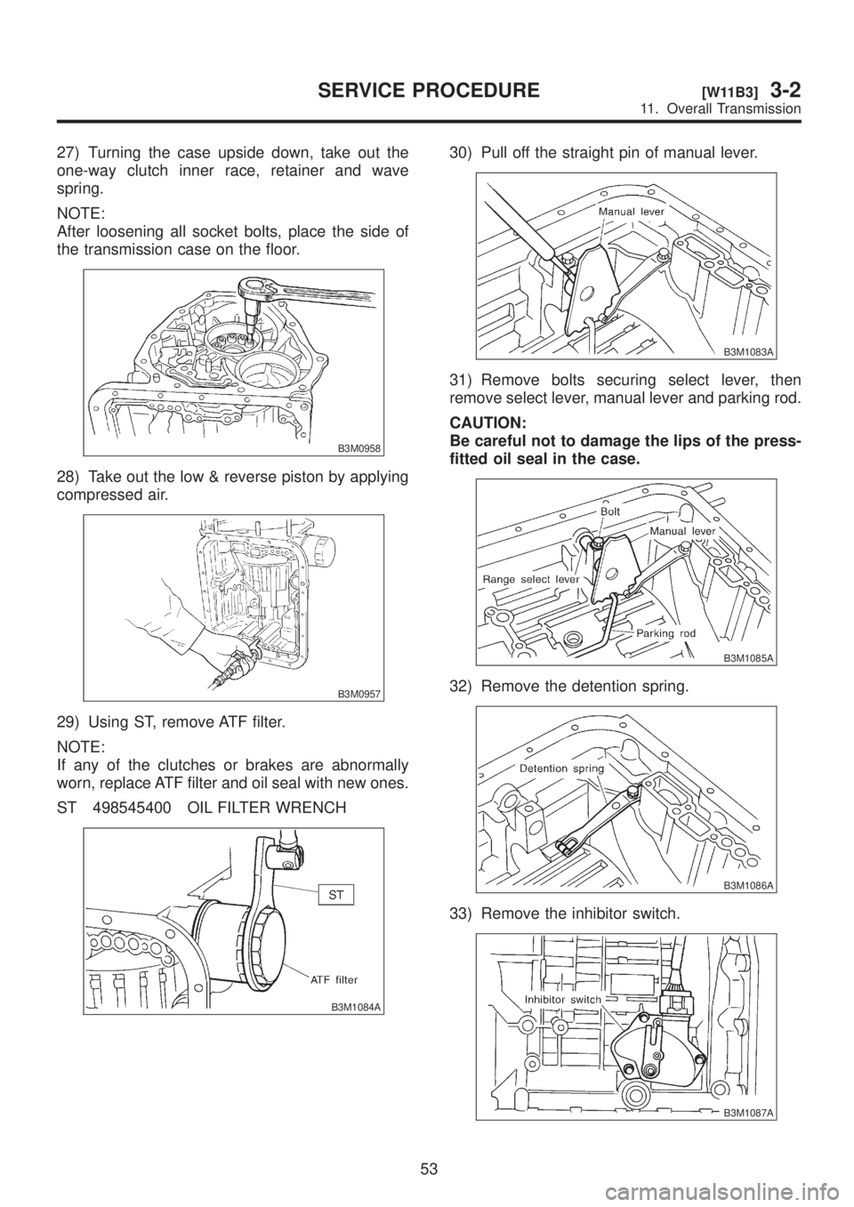
27) Turning the case upside down, take out the
one-way clutch inner race, retainer and wave
spring.
NOTE:
After loosening all socket bolts, place the side of
the transmission case on the floor.
B3M0958
28) Take out the low & reverse piston by applying
compressed air.
B3M0957
29) Using ST, remove ATF filter.
NOTE:
If any of the clutches or brakes are abnormally
worn, replace ATF filter and oil seal with new ones.
ST 498545400 OIL FILTER WRENCH
B3M1084A
30) Pull off the straight pin of manual lever.
B3M1083A
31) Remove bolts securing select lever, then
remove select lever, manual lever and parking rod.
CAUTION:
Be careful not to damage the lips of the press-
fitted oil seal in the case.
B3M1085A
32) Remove the detention spring.
B3M1086A
33) Remove the inhibitor switch.
B3M1087A
53
[W11B3]3-2SERVICE PROCEDURE
11. Overall Transmission
Page 600 of 1456
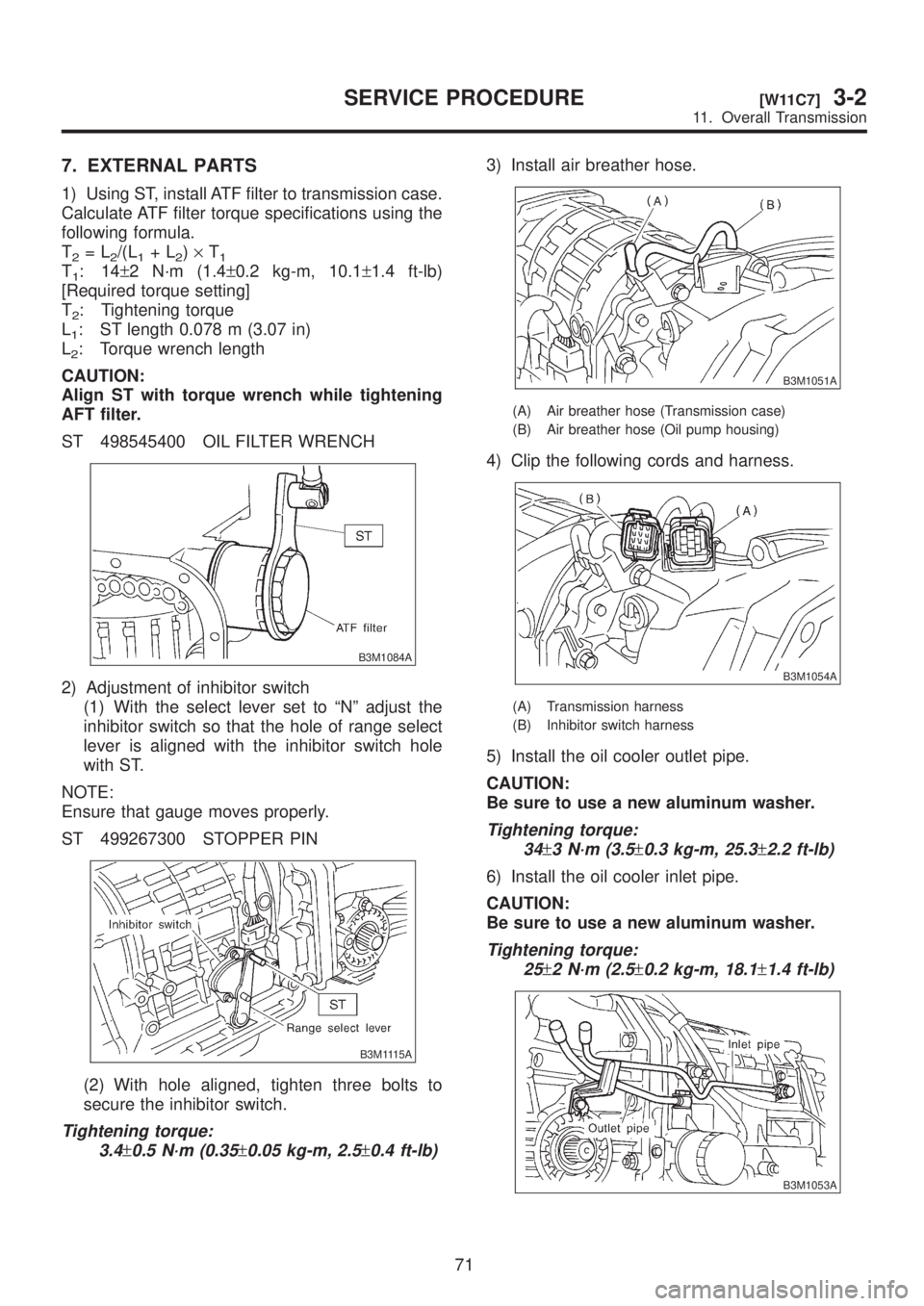
7. EXTERNAL PARTS
1) Using ST, install ATF filter to transmission case.
Calculate ATF filter torque specifications using the
following formula.
T
2=L2/(L1+L2)´T1T1:14±2 N´m (1.4±0.2 kg-m, 10.1±1.4 ft-lb)
[Required torque setting]
T
2: Tightening torque
L
1: ST length 0.078 m (3.07 in)
L
2: Torque wrench length
CAUTION:
Align ST with torque wrench while tightening
AFT filter.
ST 498545400 OIL FILTER WRENCH
B3M1084A
2) Adjustment of inhibitor switch
(1) With the select lever set to ªNº adjust the
inhibitor switch so that the hole of range select
lever is aligned with the inhibitor switch hole
with ST.
NOTE:
Ensure that gauge moves properly.
ST 499267300 STOPPER PIN
B3M1115A
(2) With hole aligned, tighten three bolts to
secure the inhibitor switch.
Tightening torque:
3.4
±0.5 N´m (0.35±0.05 kg-m, 2.5±0.4 ft-lb)
3) Install air breather hose.
B3M1051A
(A) Air breather hose (Transmission case)
(B) Air breather hose (Oil pump housing)
4) Clip the following cords and harness.
B3M1054A
(A) Transmission harness
(B) Inhibitor switch harness
5) Install the oil cooler outlet pipe.
CAUTION:
Be sure to use a new aluminum washer.
Tightening torque:
34
±3 N´m (3.5±0.3 kg-m, 25.3±2.2 ft-lb)
6) Install the oil cooler inlet pipe.
CAUTION:
Be sure to use a new aluminum washer.
Tightening torque:
25
±2 N´m (2.5±0.2 kg-m, 18.1±1.4 ft-lb)
B3M1053A
71
[W11C7]3-2SERVICE PROCEDURE
11. Overall Transmission
Page 995 of 1456
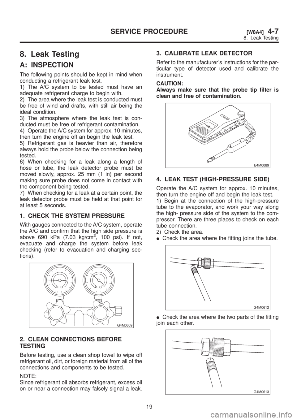
8. Leak Testing
A: INSPECTION
The following points should be kept in mind when
conducting a refrigerant leak test.
1) The A/C system to be tested must have an
adequate refrigerant charge to begin with.
2) The area where the leak test is conducted must
be free of wind and drafts, with still air being the
ideal condition.
3) The atmosphere where the leak test is con-
ducted must be free of refrigerant contamination.
4) Operate the A/C system for approx. 10 minutes,
then turn the engine off an begin the leak test.
5) Refrigerant gas is heavier than air, therefore
always hold the probe below the connection being
tested.
6) When checking for a leak along a length of
hose or tube, the leak detector probe must be
moved slowly, approx. 25 mm (1 in) per second
making sure probe does not come in contact with
the component being tested.
7) When checking for a leak at a certain point, the
leak detector probe must be held at that point for
at least 5 seconds.
1. CHECK THE SYSTEM PRESSURE
With gauges connected to the A/C system, operate
the A/C and confirm that the high side pressure is
above 690 kPa (7.03 kg/cm
2, 100 psi). If not,
evacuate and charge the system before leak
checking (refer to evacuation and charging sec-
tions).
G4M0609
2. CLEAN CONNECTIONS BEFORE
TESTING
Before testing, use a clean shop towel to wipe off
refrigerant oil, dirt, or foreign material from all of the
connections and components to be tested.
NOTE:
Since refrigerant oil absorbs refrigerant, excess oil
on or near a connection may falsely signal a leak.
3. CALIBRATE LEAK DETECTOR
Refer to the manufacturer's instructions for the par-
ticular type of detector used and calibrate the
instrument.
CAUTION:
Always make sure that the probe tip filter is
clean and free of contamination.
B4M0089
4. LEAK TEST (HIGH-PRESSURE SIDE)
Operate the A/C system for approx. 10 minutes,
then turn the engine off and begin the leak test.
1) Begin at the connection of the high-pressure
tube to the evaporator, and work your way along
the high- pressure side of the system to the com-
pressor. There are three places to check on each
tube connection.
2) Check the area.
ICheck the area where the fitting joins the tube.
G4M0612
ICheck the area where the two parts of the fitting
join each other.
G4M0613
19
[W8A4]4-7SERVICE PROCEDURE
8. Leak Testing