battery SUBARU LEGACY 1999 Service Owner's Guide
[x] Cancel search | Manufacturer: SUBARU, Model Year: 1999, Model line: LEGACY, Model: SUBARU LEGACY 1999Pages: 1456, PDF Size: 59.93 MB
Page 43 of 1456
S2M0242
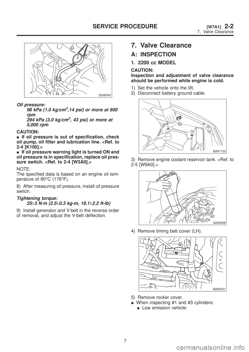
Oil pressure:
98 kPa (1.0 kg/cm2,14 psi) or more at 800
rpm
294 kPa (3.0 kg/cm
2, 43 psi) or more at
5,000 rpm
CAUTION:
IIf oil pressure is out of specification, check
oil pump, oil filter and lubrication line.
IIf oil pressure warning light is turned ON and
oil pressure is in specification, replace oil pres-
sure switch.
NOTE:
The specified data is based on an engine oil tem-
perature of 80ÉC (176ÉF).
8) After measuring oil pressure, install oil pressure
switch.
Tightening torque:
25
±3 N´m (2.5±0.3 kg-m, 18.1±2.2 ft-lb)
9) Install generator and V-belt in the reverse order
of removal, and adjust the V-belt deflection.
7. Valve Clearance
A: INSPECTION
1. 2200 cc MODEL
CAUTION:
Inspection and adjustment of valve clearance
should be performed while engine is cold.
1) Set the vehicle onto the lift.
2) Disconnect battery ground cable.
B2M1723
3) Remove engine coolant reservoir tank.
S2M0028
4) Remove timing belt cover (LH).
B2M2031
5) Remove rocker cover.
IWhen inspecting #1 and #3 cylinders:
ILow emission vehicle:
7
[W7A1]2-2SERVICE PROCEDURE
7. Valve Clearance
Page 45 of 1456
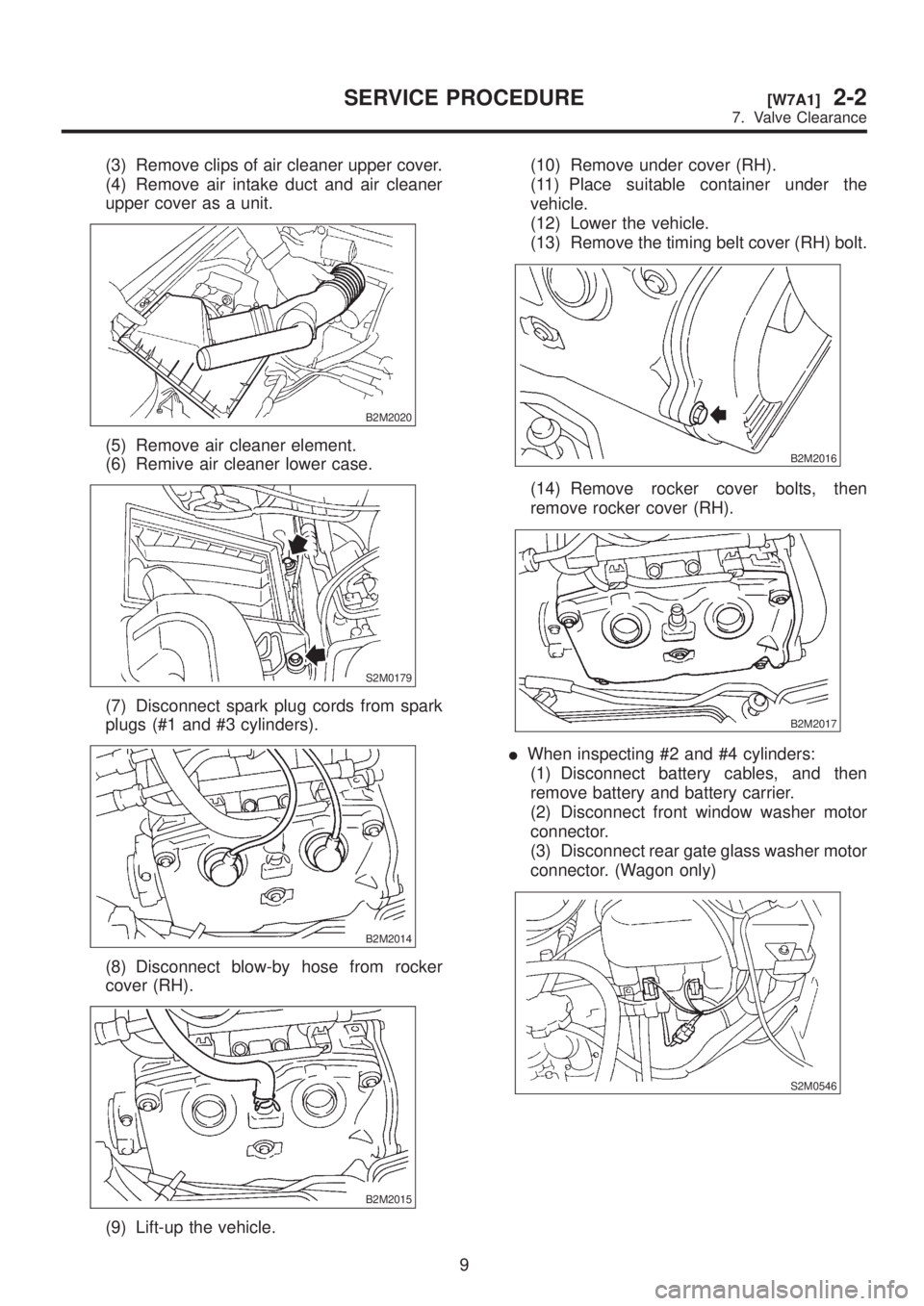
(3) Remove clips of air cleaner upper cover.
(4) Remove air intake duct and air cleaner
upper cover as a unit.
B2M2020
(5) Remove air cleaner element.
(6) Remive air cleaner lower case.
S2M0179
(7) Disconnect spark plug cords from spark
plugs (#1 and #3 cylinders).
B2M2014
(8) Disconnect blow-by hose from rocker
cover (RH).
B2M2015
(9) Lift-up the vehicle.(10) Remove under cover (RH).
(11) Place suitable container under the
vehicle.
(12) Lower the vehicle.
(13) Remove the timing belt cover (RH) bolt.
B2M2016
(14) Remove rocker cover bolts, then
remove rocker cover (RH).
B2M2017
IWhen inspecting #2 and #4 cylinders:
(1) Disconnect battery cables, and then
remove battery and battery carrier.
(2) Disconnect front window washer motor
connector.
(3) Disconnect rear gate glass washer motor
connector. (Wagon only)
S2M0546
9
[W7A1]2-2SERVICE PROCEDURE
7. Valve Clearance
Page 47 of 1456
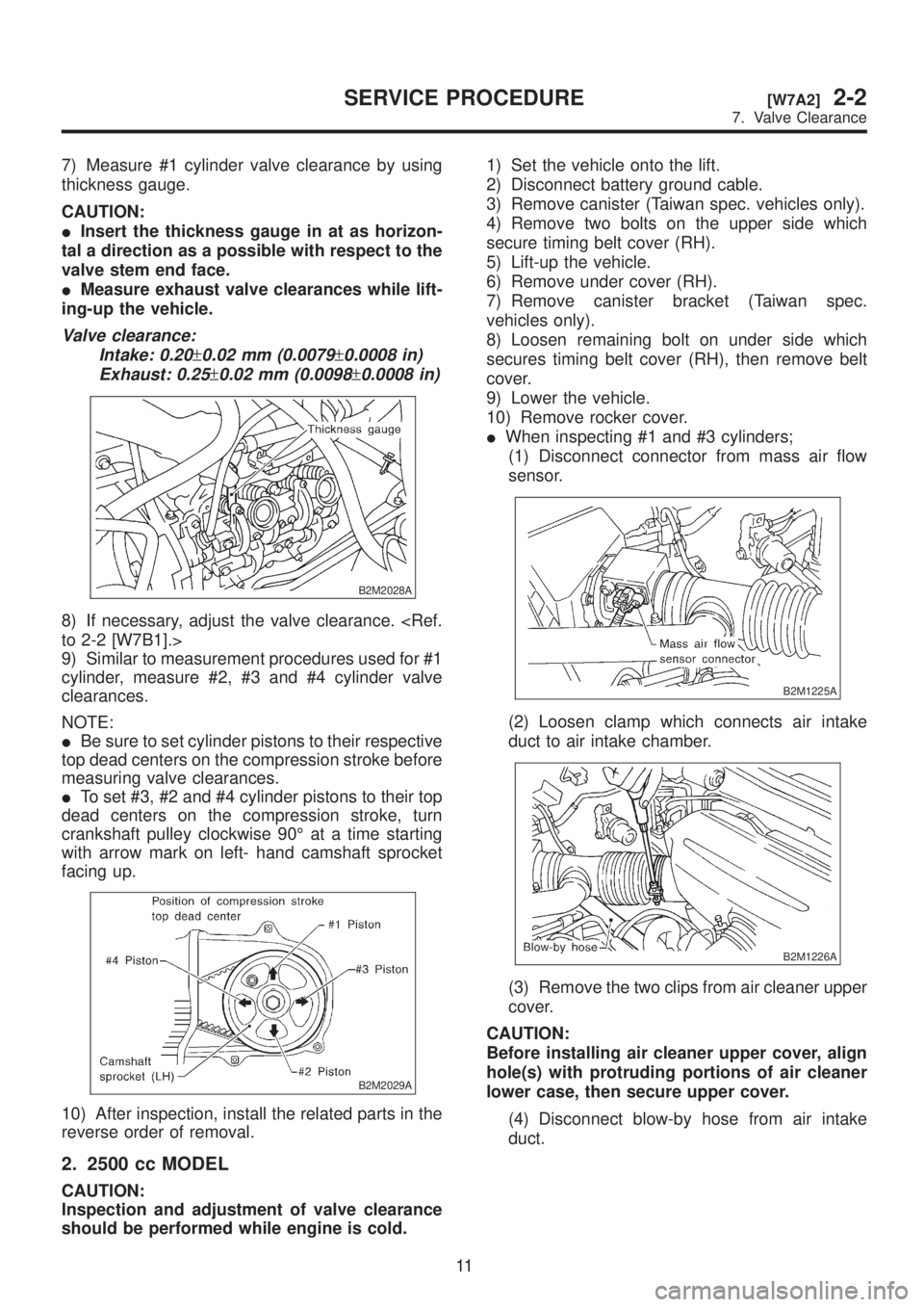
7) Measure #1 cylinder valve clearance by using
thickness gauge.
CAUTION:
IInsert the thickness gauge in at as horizon-
tal a direction as a possible with respect to the
valve stem end face.
IMeasure exhaust valve clearances while lift-
ing-up the vehicle.
Valve clearance:
Intake: 0.20
±0.02 mm (0.0079±0.0008 in)
Exhaust: 0.25
±0.02 mm (0.0098±0.0008 in)
B2M2028A
8) If necessary, adjust the valve clearance.
9) Similar to measurement procedures used for #1
cylinder, measure #2, #3 and #4 cylinder valve
clearances.
NOTE:
IBe sure to set cylinder pistons to their respective
top dead centers on the compression stroke before
measuring valve clearances.
ITo set #3, #2 and #4 cylinder pistons to their top
dead centers on the compression stroke, turn
crankshaft pulley clockwise 90É at a time starting
with arrow mark on left- hand camshaft sprocket
facing up.
B2M2029A
10) After inspection, install the related parts in the
reverse order of removal.
2. 2500 cc MODEL
CAUTION:
Inspection and adjustment of valve clearance
should be performed while engine is cold.1) Set the vehicle onto the lift.
2) Disconnect battery ground cable.
3) Remove canister (Taiwan spec. vehicles only).
4) Remove two bolts on the upper side which
secure timing belt cover (RH).
5) Lift-up the vehicle.
6) Remove under cover (RH).
7) Remove canister bracket (Taiwan spec.
vehicles only).
8) Loosen remaining bolt on under side which
secures timing belt cover (RH), then remove belt
cover.
9) Lower the vehicle.
10) Remove rocker cover.
IWhen inspecting #1 and #3 cylinders;
(1) Disconnect connector from mass air flow
sensor.
B2M1225A
(2) Loosen clamp which connects air intake
duct to air intake chamber.
B2M1226A
(3) Remove the two clips from air cleaner upper
cover.
CAUTION:
Before installing air cleaner upper cover, align
hole(s) with protruding portions of air cleaner
lower case, then secure upper cover.
(4) Disconnect blow-by hose from air intake
duct.
11
[W7A2]2-2SERVICE PROCEDURE
7. Valve Clearance
Page 48 of 1456
(5) Remove air intake duct and air cleaner
upper cover as a unit.
B2M1227
(6) Remove air cleaner element.
(7) Remove air cleaner lower case.
S2M0179
(8) Disconnect spark plug cords from spark
plugs (#1 and #3 cylinders).
(9) Place suitable container under the vehicle.
(10) Disconnect PCV hose from rocker cover
(RH).
(11) Remove bolts, then remove rocker cover
(RH).
IWhen inspecting # 2 and #4 cylinders;
(1) Disconnect battery cables, and then
remove battery and battery carrier.
(2) Disconnect washer motor connectors.
(3) Disconnect washer hoses from washer
motors, then plug connections with suitable
caps.
(4) Remove washer tank.
(5) Disconnect spark plug cords from spark
plugs (#2 and #4 cylinders).
(6) Remove under cover (LH).
(7) Place suitable container under the vehicle.
(8) Disconnect PCV hose from rocker cover
(LH).
(9) Remove bolts, then remove rocker cover
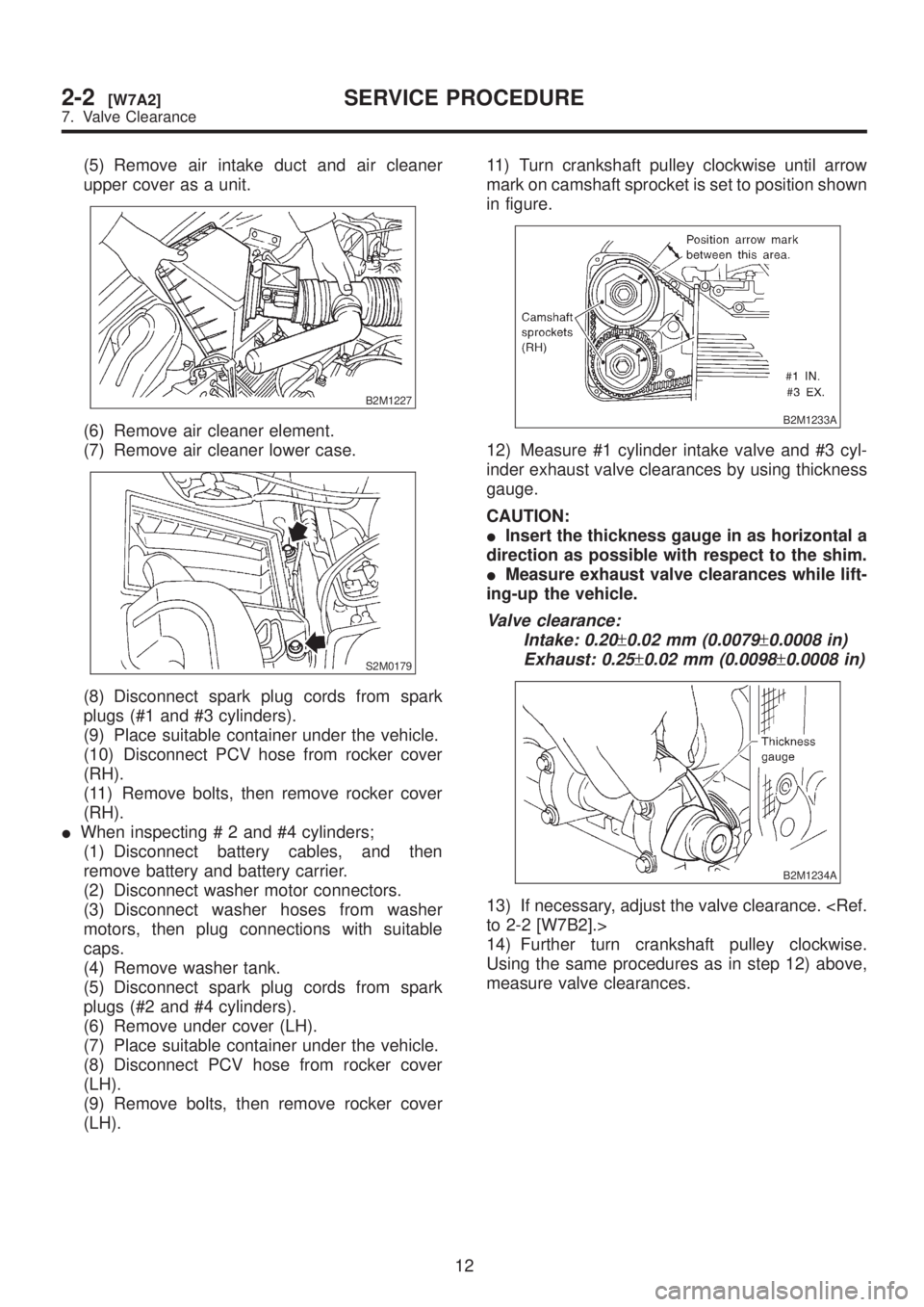
(LH).11) Turn crankshaft pulley clockwise until arrow
mark on camshaft sprocket is set to position shown
in figure.
B2M1233A
12) Measure #1 cylinder intake valve and #3 cyl-
inder exhaust valve clearances by using thickness
gauge.
CAUTION:
IInsert the thickness gauge in as horizontal a
direction as possible with respect to the shim.
IMeasure exhaust valve clearances while lift-
ing-up the vehicle.
Valve clearance:
Intake: 0.20
±0.02 mm (0.0079±0.0008 in)
Exhaust: 0.25
±0.02 mm (0.0098±0.0008 in)
B2M1234A
13) If necessary, adjust the valve clearance.
14) Further turn crankshaft pulley clockwise.
Using the same procedures as in step 12) above,
measure valve clearances.
12
2-2[W7A2]SERVICE PROCEDURE
7. Valve Clearance
Page 127 of 1456
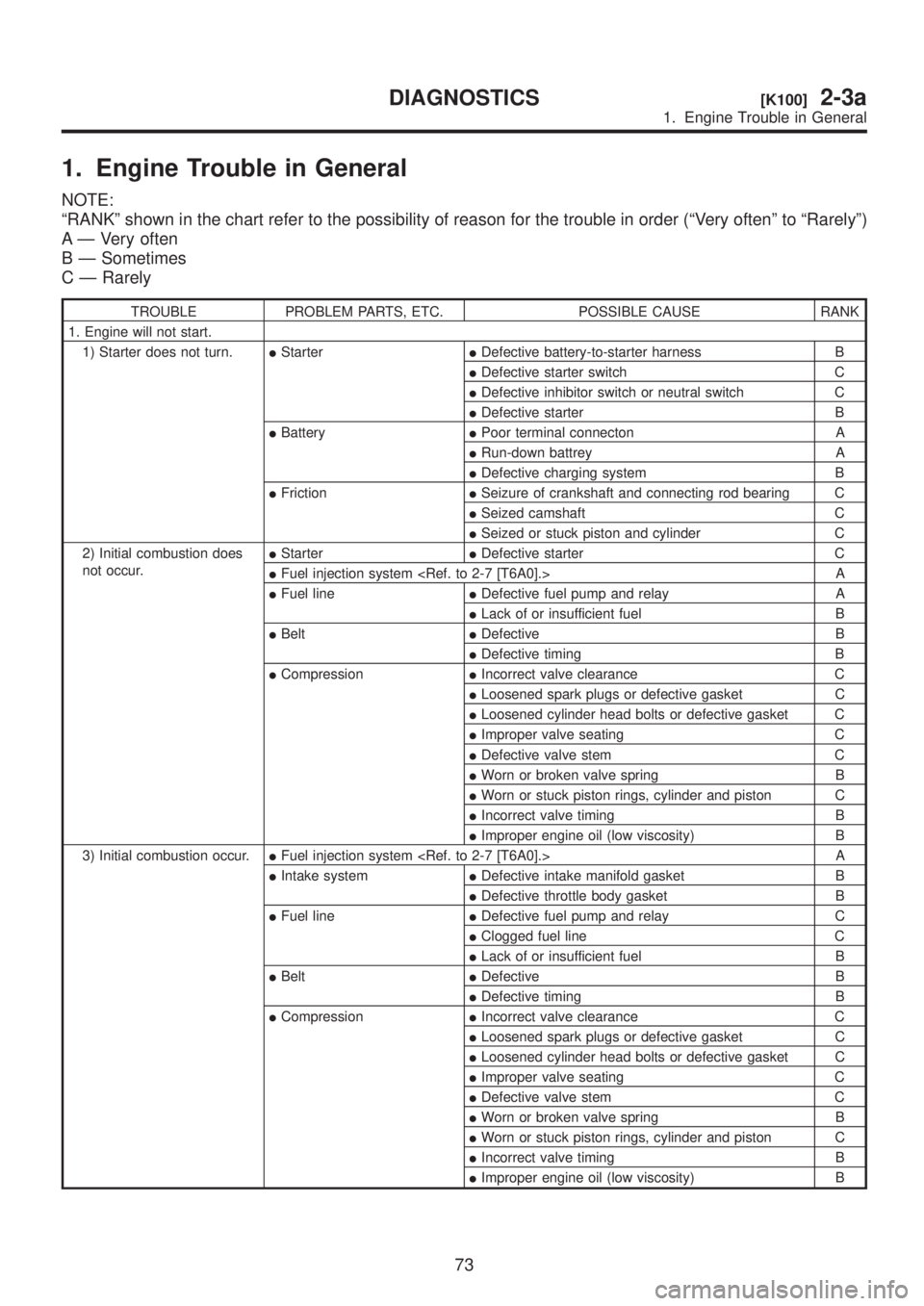
1. Engine Trouble in General
NOTE:
ªRANKº shown in the chart refer to the possibility of reason for the trouble in order (ªVery oftenº to ªRarelyº)
A Ð Very often
B Ð Sometimes
C Ð Rarely
TROUBLE PROBLEM PARTS, ETC. POSSIBLE CAUSE RANK
1. Engine will not start.
1) Starter does not turn.IStarterIDefective battery-to-starter harness B
IDefective starter switch C
IDefective inhibitor switch or neutral switch C
IDefective starter B
IBatteryIPoor terminal connecton A
IRun-down battrey A
IDefective charging system B
IFrictionISeizure of crankshaft and connecting rod bearing C
ISeized camshaft C
ISeized or stuck piston and cylinder C
2) Initial combustion does
not occur.IStarterIDefective starter C
IFuel injection system
IFuel lineIDefective fuel pump and relay A
ILack of or insufficient fuel B
IBeltIDefective B
IDefective timing B
ICompressionIIncorrect valve clearance C
ILoosened spark plugs or defective gasket C
ILoosened cylinder head bolts or defective gasket C
IImproper valve seating C
IDefective valve stem C
IWorn or broken valve spring B
IWorn or stuck piston rings, cylinder and piston C
IIncorrect valve timing B
IImproper engine oil (low viscosity) B
3) Initial combustion occur.IFuel injection system
IIntake systemIDefective intake manifold gasket B
IDefective throttle body gasket B
IFuel lineIDefective fuel pump and relay C
IClogged fuel line C
ILack of or insufficient fuel B
IBeltIDefective B
IDefective timing B
ICompressionIIncorrect valve clearance C
ILoosened spark plugs or defective gasket C
ILoosened cylinder head bolts or defective gasket C
IImproper valve seating C
IDefective valve stem C
IWorn or broken valve spring B
IWorn or stuck piston rings, cylinder and piston C
IIncorrect valve timing B
IImproper engine oil (low viscosity) B
73
[K100]2-3aDIAGNOSTICS
1. Engine Trouble in General
Page 202 of 1456
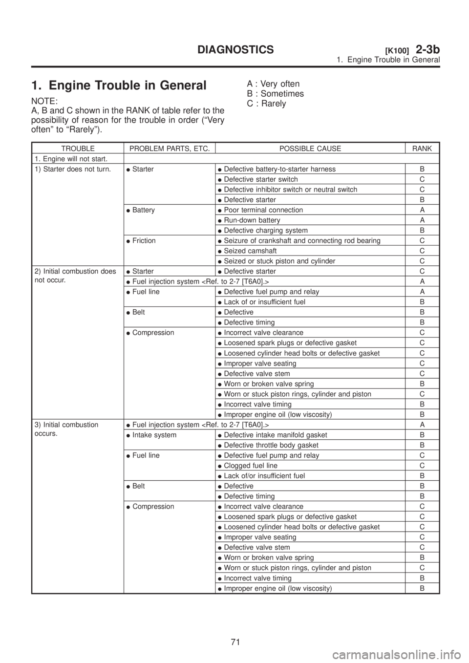
1. Engine Trouble in General
NOTE:
A, B and C shown in the RANK of table refer to the
possibility of reason for the trouble in order (ªVery
oftenº to ªRarelyº).A : Very often
B : Sometimes
C : Rarely
TROUBLE PROBLEM PARTS, ETC. POSSIBLE CAUSE RANK
1. Engine will not start.
1) Starter does not turn.IStarterIDefective battery-to-starter harness B
IDefective starter switch C
IDefective inhibitor switch or neutral switch C
IDefective starter B
IBatteryIPoor terminal connection A
IRun-down battery A
IDefective charging system B
IFrictionISeizure of crankshaft and connecting rod bearing C
ISeized camshaft C
ISeized or stuck piston and cylinder C
2) Initial combustion does
not occur.IStarterIDefective starter C
IFuel injection system
IFuel lineIDefective fuel pump and relay A
ILack of or insufficient fuel B
IBeltIDefective B
IDefective timing B
ICompressionIIncorrect valve clearance C
ILoosened spark plugs or defective gasket C
ILoosened cylinder head bolts or defective gasket C
IImproper valve seating C
IDefective valve stem C
IWorn or broken valve spring B
IWorn or stuck piston rings, cylinder and piston C
IIncorrect valve timing B
IImproper engine oil (low viscosity) B
3) Initial combustion
occurs.IFuel injection system
IIntake systemIDefective intake manifold gasket B
IDefective throttle body gasket B
IFuel lineIDefective fuel pump and relay C
IClogged fuel line C
ILack of/or insufficient fuel B
IBeltIDefective B
IDefective timing B
ICompressionIIncorrect valve clearance C
ILoosened spark plugs or defective gasket C
ILoosened cylinder head bolts or defective gasket C
IImproper valve seating C
IDefective valve stem C
IWorn or broken valve spring B
IWorn or stuck piston rings, cylinder and piston C
IIncorrect valve timing B
IImproper engine oil (low viscosity) B
71
[K100]2-3bDIAGNOSTICS
1. Engine Trouble in General
Page 212 of 1456
![SUBARU LEGACY 1999 Service Owners Guide 1. Oil Pump
A: REMOVAL
1) Disconnect battery ground cable.
G6M0095
2) Lift-up the vehicle.
3) Remove under cover.
B2M0014
4) Drain coolant. <Ref. to 2-5 [W1A0].>
B2M0015A
5) Remove radiator. <Ref. to SUBARU LEGACY 1999 Service Owners Guide 1. Oil Pump
A: REMOVAL
1) Disconnect battery ground cable.
G6M0095
2) Lift-up the vehicle.
3) Remove under cover.
B2M0014
4) Drain coolant. <Ref. to 2-5 [W1A0].>
B2M0015A
5) Remove radiator. <Ref. to](/img/17/57435/w960_57435-211.png)
1. Oil Pump
A: REMOVAL
1) Disconnect battery ground cable.
G6M0095
2) Lift-up the vehicle.
3) Remove under cover.
B2M0014
4) Drain coolant.
B2M0015A
5) Remove radiator.
S2M0033
6) Lower the vehicle.
7) Remove crankshaft position sensor.
B2M1252A
8) Remove camshaft position sensor.
G2M0417
9) Remove V-belts.
G2M0286
10) Remove rear side V-belt tensioner.
S2M0113
6
2-4[W1A0]SERVICE PROCEDURE
1. Oil Pump
Page 216 of 1456
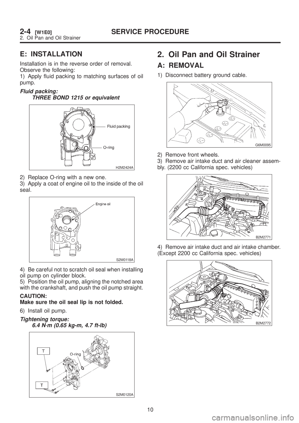
E: INSTALLATION
Installation is in the reverse order of removal.
Observe the following:
1) Apply fluid packing to matching surfaces of oil
pump.
Fluid packing:
THREE BOND 1215 or equivalent
H2M2424A
2) Replace O-ring with a new one.
3) Apply a coat of engine oil to the inside of the oil
seal.
S2M0118A
4) Be careful not to scratch oil seal when installing
oil pump on cylinder block.
5) Position the oil pump, aligning the notched area
with the crankshaft, and push the oil pump straight.
CAUTION:
Make sure the oil seal lip is not folded.
6) Install oil pump.
Tightening torque:
6.4 N´m (0.65 kg-m, 4.7 ft-lb)
S2M0120A
2. Oil Pan and Oil Strainer
A: REMOVAL
1) Disconnect battery ground cable.
G6M0095
2) Remove front wheels.
3) Remove air intake duct and air cleaner assem-
bly. (2200 cc California spec. vehicles)
B2M2771
4) Remove air intake duct and air intake chamber.
(Except 2200 cc California spec. vehicles)
B2M2772
10
2-4[W1E0]SERVICE PROCEDURE
2. Oil Pan and Oil Strainer
Page 217 of 1456
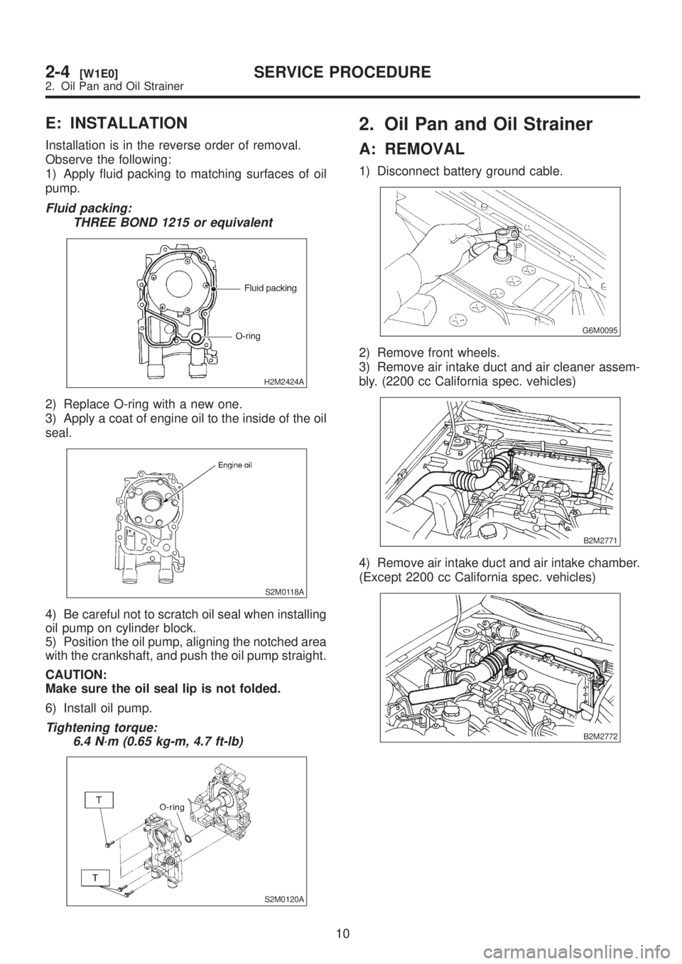
E: INSTALLATION
Installation is in the reverse order of removal.
Observe the following:
1) Apply fluid packing to matching surfaces of oil
pump.
Fluid packing:
THREE BOND 1215 or equivalent
H2M2424A
2) Replace O-ring with a new one.
3) Apply a coat of engine oil to the inside of the oil
seal.
S2M0118A
4) Be careful not to scratch oil seal when installing
oil pump on cylinder block.
5) Position the oil pump, aligning the notched area
with the crankshaft, and push the oil pump straight.
CAUTION:
Make sure the oil seal lip is not folded.
6) Install oil pump.
Tightening torque:
6.4 N´m (0.65 kg-m, 4.7 ft-lb)
S2M0120A
2. Oil Pan and Oil Strainer
A: REMOVAL
1) Disconnect battery ground cable.
G6M0095
2) Remove front wheels.
3) Remove air intake duct and air cleaner assem-
bly. (2200 cc California spec. vehicles)
B2M2771
4) Remove air intake duct and air intake chamber.
(Except 2200 cc California spec. vehicles)
B2M2772
10
2-4[W1E0]SERVICE PROCEDURE
2. Oil Pan and Oil Strainer
Page 236 of 1456
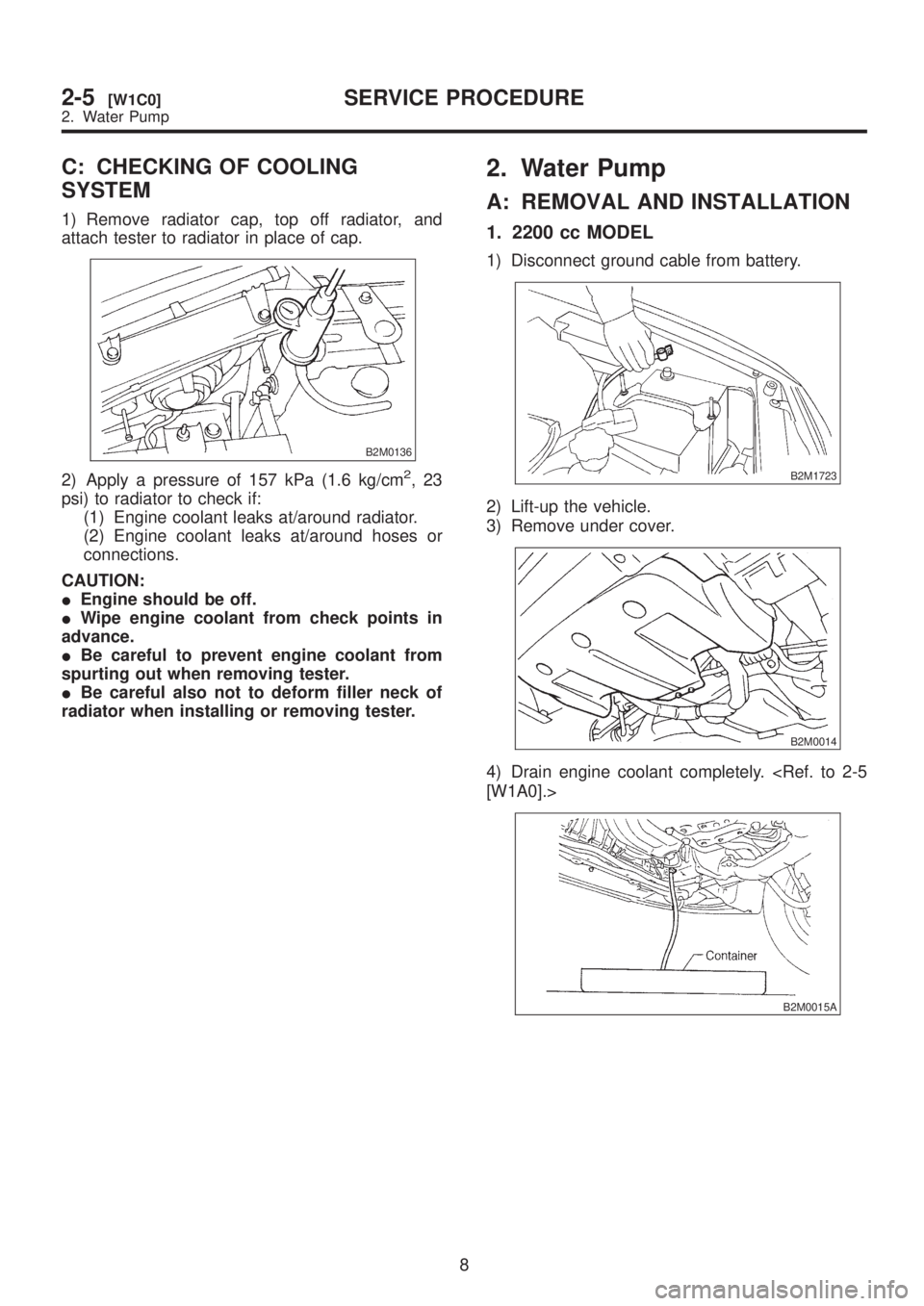
C: CHECKING OF COOLING
SYSTEM
1) Remove radiator cap, top off radiator, and
attach tester to radiator in place of cap.
B2M0136
2) Apply a pressure of 157 kPa (1.6 kg/cm2,23
psi) to radiator to check if:
(1) Engine coolant leaks at/around radiator.
(2) Engine coolant leaks at/around hoses or
connections.
CAUTION:
IEngine should be off.
IWipe engine coolant from check points in
advance.
IBe careful to prevent engine coolant from
spurting out when removing tester.
IBe careful also not to deform filler neck of
radiator when installing or removing tester.
2. Water Pump
A: REMOVAL AND INSTALLATION
1. 2200 cc MODEL
1) Disconnect ground cable from battery.
B2M1723
2) Lift-up the vehicle.
3) Remove under cover.
B2M0014
4) Drain engine coolant completely.
B2M0015A
8
2-5[W1C0]SERVICE PROCEDURE
2. Water Pump