parking brake SUBARU LEGACY 1999 Service Owner's Guide
[x] Cancel search | Manufacturer: SUBARU, Model Year: 1999, Model line: LEGACY, Model: SUBARU LEGACY 1999Pages: 1456, PDF Size: 59.93 MB
Page 782 of 1456
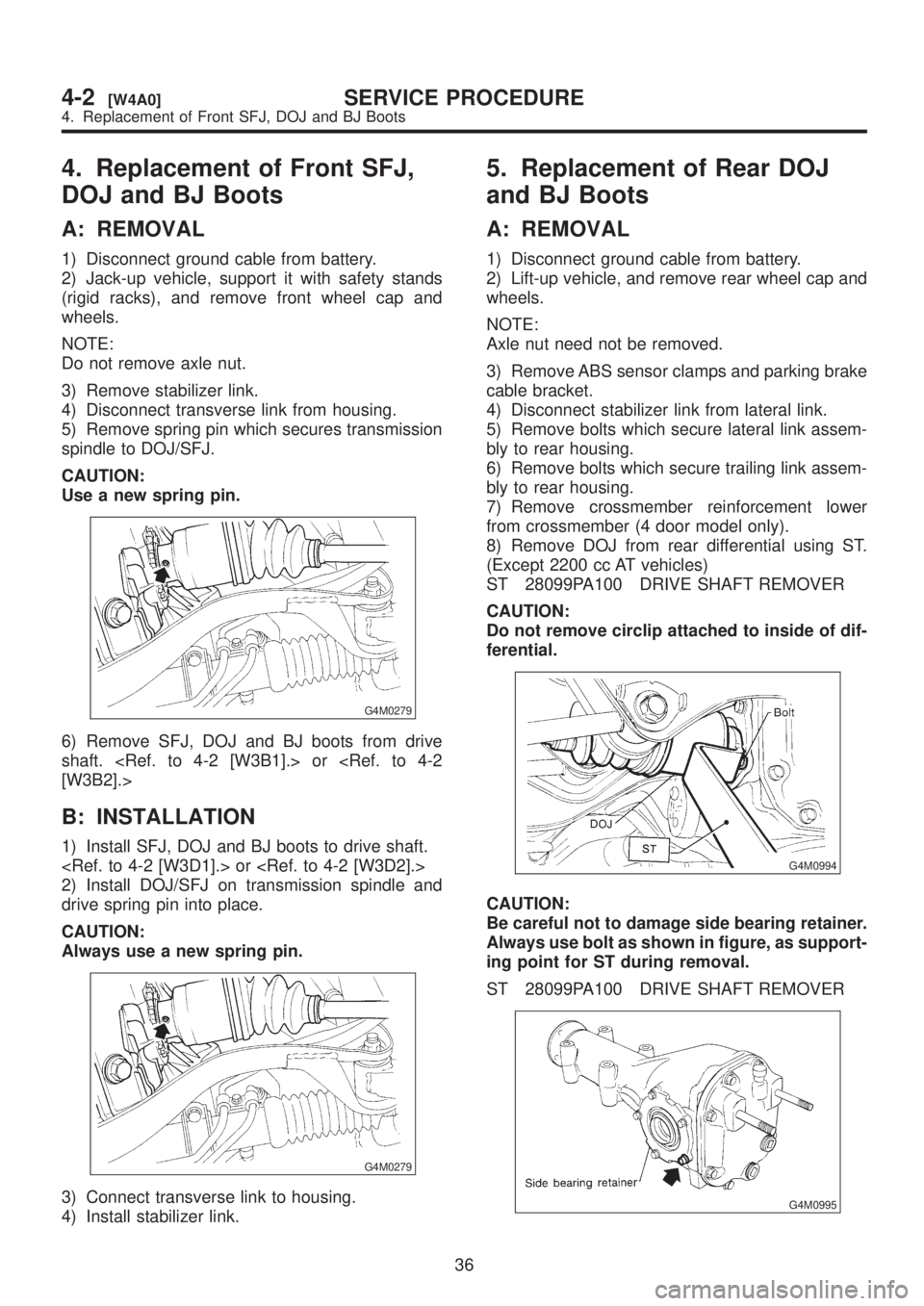
4. Replacement of Front SFJ,
DOJ and BJ Boots
A: REMOVAL
1) Disconnect ground cable from battery.
2) Jack-up vehicle, support it with safety stands
(rigid racks), and remove front wheel cap and
wheels.
NOTE:
Do not remove axle nut.
3) Remove stabilizer link.
4) Disconnect transverse link from housing.
5) Remove spring pin which secures transmission
spindle to DOJ/SFJ.
CAUTION:
Use a new spring pin.
G4M0279
6) Remove SFJ, DOJ and BJ boots from drive
shaft.
B: INSTALLATION
1) Install SFJ, DOJ and BJ boots to drive shaft.
2) Install DOJ/SFJ on transmission spindle and
drive spring pin into place.
CAUTION:
Always use a new spring pin.
G4M0279
3) Connect transverse link to housing.
4) Install stabilizer link.
5. Replacement of Rear DOJ
and BJ Boots
A: REMOVAL
1) Disconnect ground cable from battery.
2) Lift-up vehicle, and remove rear wheel cap and
wheels.
NOTE:
Axle nut need not be removed.
3) Remove ABS sensor clamps and parking brake
cable bracket.
4) Disconnect stabilizer link from lateral link.
5) Remove bolts which secure lateral link assem-
bly to rear housing.
6) Remove bolts which secure trailing link assem-
bly to rear housing.
7) Remove crossmember reinforcement lower
from crossmember (4 door model only).
8) Remove DOJ from rear differential using ST.
(Except 2200 cc AT vehicles)
ST 28099PA100 DRIVE SHAFT REMOVER
CAUTION:
Do not remove circlip attached to inside of dif-
ferential.
G4M0994
CAUTION:
Be careful not to damage side bearing retainer.
Always use bolt as shown in figure, as support-
ing point for ST during removal.
ST 28099PA100 DRIVE SHAFT REMOVER
G4M0995
36
4-2[W4A0]SERVICE PROCEDURE
4. Replacement of Front SFJ, DOJ and BJ Boots
Page 783 of 1456
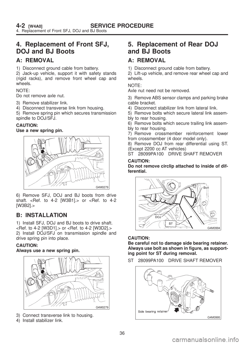
4. Replacement of Front SFJ,
DOJ and BJ Boots
A: REMOVAL
1) Disconnect ground cable from battery.
2) Jack-up vehicle, support it with safety stands
(rigid racks), and remove front wheel cap and
wheels.
NOTE:
Do not remove axle nut.
3) Remove stabilizer link.
4) Disconnect transverse link from housing.
5) Remove spring pin which secures transmission
spindle to DOJ/SFJ.
CAUTION:
Use a new spring pin.
G4M0279
6) Remove SFJ, DOJ and BJ boots from drive
shaft.
B: INSTALLATION
1) Install SFJ, DOJ and BJ boots to drive shaft.
2) Install DOJ/SFJ on transmission spindle and
drive spring pin into place.
CAUTION:
Always use a new spring pin.
G4M0279
3) Connect transverse link to housing.
4) Install stabilizer link.
5. Replacement of Rear DOJ
and BJ Boots
A: REMOVAL
1) Disconnect ground cable from battery.
2) Lift-up vehicle, and remove rear wheel cap and
wheels.
NOTE:
Axle nut need not be removed.
3) Remove ABS sensor clamps and parking brake
cable bracket.
4) Disconnect stabilizer link from lateral link.
5) Remove bolts which secure lateral link assem-
bly to rear housing.
6) Remove bolts which secure trailing link assem-
bly to rear housing.
7) Remove crossmember reinforcement lower
from crossmember (4 door model only).
8) Remove DOJ from rear differential using ST.
(Except 2200 cc AT vehicles)
ST 28099PA100 DRIVE SHAFT REMOVER
CAUTION:
Do not remove circlip attached to inside of dif-
ferential.
G4M0994
CAUTION:
Be careful not to damage side bearing retainer.
Always use bolt as shown in figure, as support-
ing point for ST during removal.
ST 28099PA100 DRIVE SHAFT REMOVER
G4M0995
36
4-2[W4A0]SERVICE PROCEDURE
4. Replacement of Front SFJ, DOJ and BJ Boots
Page 785 of 1456
assembly, and tighten self-locking nut.
9) Connect stabilizer link to lateral link.
10) Install crossmember reinforcement lower to
crossmember (4 door model only).
11) Install ABS sensor clamps and parking brake
cable bracket.6. Full Wheel Cap
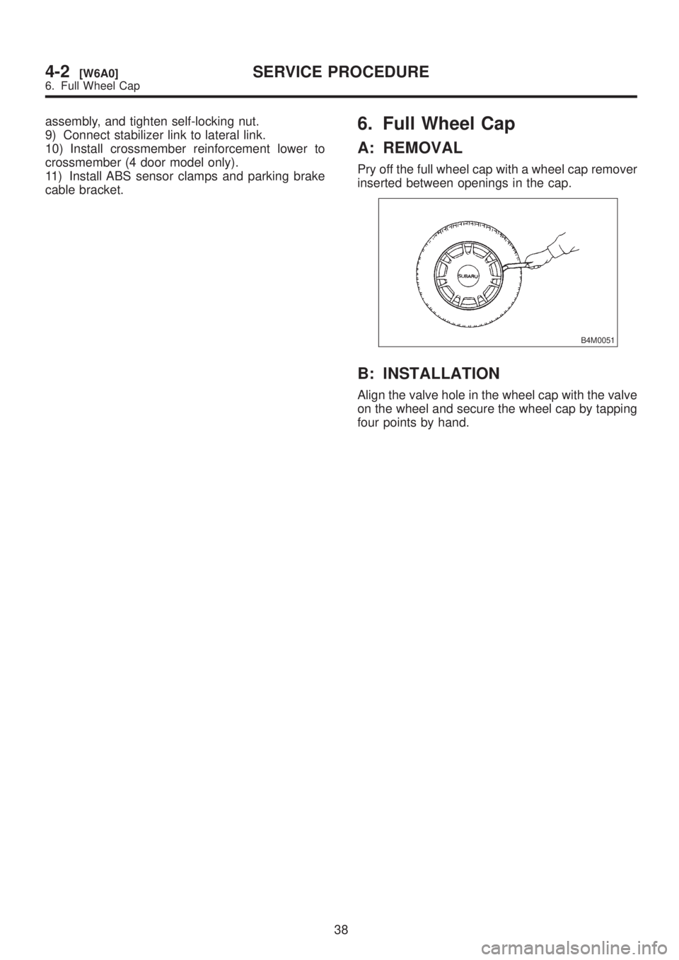
A: REMOVAL
Pry off the full wheel cap with a wheel cap remover
inserted between openings in the cap.
B4M0051
B: INSTALLATION
Align the valve hole in the wheel cap with the valve
on the wheel and secure the wheel cap by tapping
four points by hand.
38
4-2[W6A0]SERVICE PROCEDURE
6. Full Wheel Cap
Page 786 of 1456
assembly, and tighten self-locking nut.
9) Connect stabilizer link to lateral link.
10) Install crossmember reinforcement lower to
crossmember (4 door model only).
11) Install ABS sensor clamps and parking brake
cable bracket.6. Full Wheel Cap
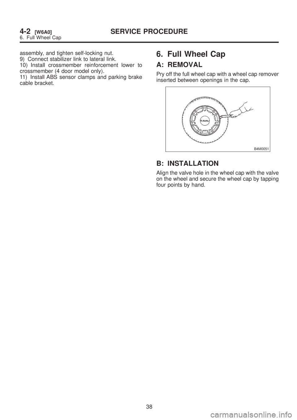
A: REMOVAL
Pry off the full wheel cap with a wheel cap remover
inserted between openings in the cap.
B4M0051
B: INSTALLATION
Align the valve hole in the wheel cap with the valve
on the wheel and secure the wheel cap by tapping
four points by hand.
38
4-2[W6A0]SERVICE PROCEDURE
6. Full Wheel Cap
Page 868 of 1456
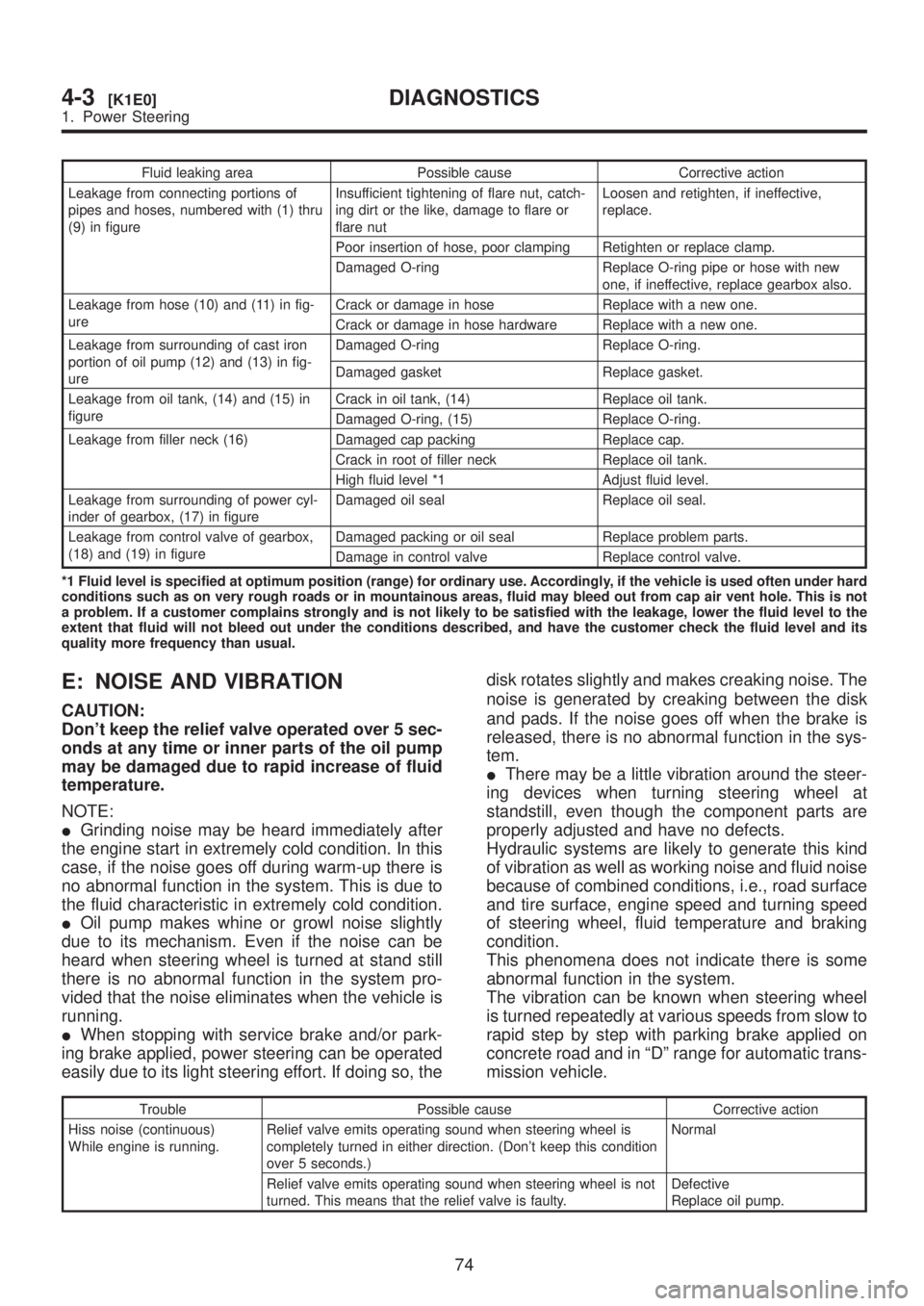
Fluid leaking area Possible cause Corrective action
Leakage from connecting portions of
pipes and hoses, numbered with (1) thru
(9) in figureInsufficient tightening of flare nut, catch-
ing dirt or the like, damage to flare or
flare nutLoosen and retighten, if ineffective,
replace.
Poor insertion of hose, poor clamping Retighten or replace clamp.
Damaged O-ring Replace O-ring pipe or hose with new
one, if ineffective, replace gearbox also.
Leakage from hose (10) and (11) in fig-
ureCrack or damage in hose Replace with a new one.
Crack or damage in hose hardware Replace with a new one.
Leakage from surrounding of cast iron
portion of oil pump (12) and (13) in fig-
ureDamaged O-ring Replace O-ring.
Damaged gasket Replace gasket.
Leakage from oil tank, (14) and (15) in
figureCrack in oil tank, (14) Replace oil tank.
Damaged O-ring, (15) Replace O-ring.
Leakage from filler neck (16) Damaged cap packing Replace cap.
Crack in root of filler neck Replace oil tank.
High fluid level *1 Adjust fluid level.
Leakage from surrounding of power cyl-
inder of gearbox, (17) in figureDamaged oil seal Replace oil seal.
Leakage from control valve of gearbox,
(18) and (19) in figureDamaged packing or oil seal Replace problem parts.
Damage in control valve Replace control valve.
*1 Fluid level is specified at optimum position (range) for ordinary use. Accordingly, if the vehicle is used often under hard
conditions such as on very rough roads or in mountainous areas, fluid may bleed out from cap air vent hole. This is not
a problem. If a customer complains strongly and is not likely to be satisfied with the leakage, lower the fluid level to the
extent that fluid will not bleed out under the conditions described, and have the customer check the fluid level and its
quality more frequency than usual.
E: NOISE AND VIBRATION
CAUTION:
Don't keep the relief valve operated over 5 sec-
onds at any time or inner parts of the oil pump
may be damaged due to rapid increase of fluid
temperature.
NOTE:
IGrinding noise may be heard immediately after
the engine start in extremely cold condition. In this
case, if the noise goes off during warm-up there is
no abnormal function in the system. This is due to
the fluid characteristic in extremely cold condition.
IOil pump makes whine or growl noise slightly
due to its mechanism. Even if the noise can be
heard when steering wheel is turned at stand still
there is no abnormal function in the system pro-
vided that the noise eliminates when the vehicle is
running.
IWhen stopping with service brake and/or park-
ing brake applied, power steering can be operated
easily due to its light steering effort. If doing so, thedisk rotates slightly and makes creaking noise. The
noise is generated by creaking between the disk
and pads. If the noise goes off when the brake is
released, there is no abnormal function in the sys-
tem.
IThere may be a little vibration around the steer-
ing devices when turning steering wheel at
standstill, even though the component parts are
properly adjusted and have no defects.
Hydraulic systems are likely to generate this kind
of vibration as well as working noise and fluid noise
because of combined conditions, i.e., road surface
and tire surface, engine speed and turning speed
of steering wheel, fluid temperature and braking
condition.
This phenomena does not indicate there is some
abnormal function in the system.
The vibration can be known when steering wheel
is turned repeatedly at various speeds from slow to
rapid step by step with parking brake applied on
concrete road and in ªDº range for automatic trans-
mission vehicle.
Trouble Possible cause Corrective action
Hiss noise (continuous)
While engine is running.Relief valve emits operating sound when steering wheel is
completely turned in either direction. (Don't keep this condition
over 5 seconds.)Normal
Relief valve emits operating sound when steering wheel is not
turned. This means that the relief valve is faulty.Defective
Replace oil pump.
74
4-3[K1E0]DIAGNOSTICS
1. Power Steering
Page 869 of 1456
![SUBARU LEGACY 1999 Service Owners Guide Trouble Possible cause Corrective action
Rattling noise (intermittent)
While engine is running.Interference with adjacent parts Check clearance.
Correct if necessary.
<Ref. to 4-3 [K1F0].>
Loosened in](/img/17/57435/w960_57435-868.png "SUBARU LEGACY 1999 Service Owners Guide Trouble Possible cause Corrective action
Rattling noise (intermittent)
While engine is running.Interference with adjacent parts Check clearance.
Correct if necessary.
<Ref. to 4-3 [K1F0].>
Loosened in")
Trouble Possible cause Corrective action
Rattling noise (intermittent)
While engine is running.Interference with adjacent parts Check clearance.
Correct if necessary.
Loosened installation of oil pump, oil tank, pump bracket, gear-
box or crossmemberRetighten.
Loosened installation of oil pump pulley or other pulley(s) Retighten.
Loosened linkage or play of steering or suspension
Loosened tightening of joint or steering columnRetighten or replace.
Sound generates from the inside of gearbox or oil pump. Replace the gearbox or oil
pump.
Knocking
When turning steering wheel
in both direction with small
angle repeatedly at engine
ON or OFF.Excessive backlash
Loosened lock nut for adjusting backlashAdjust and retighten.
Loosened tightening or play of tie-rod, tie-rod end Retighten or replace.
Grinding noise (continuous)
While engine is running.Vane pump aeration Inspect and retighten fluid line
connection.
Refill fluid and vent air.
Vane pump seizing Replace oil pump.
Pulley bearing seizing of oil pump Replace oil pump.
Folded hose, flat pipe Replace.
Squeal, squeak (intermittent
or continuous)
While engine is running.Maladjustment of pulley belt
Damaged or charged pulley belt
Unequal length of pulley beltsAdjust or replace.
(Replace two belts as a set.)
Run out or soilage of V-groove surface of oil pump pulley Clean or replace.
Sizzling noise (continuous)
While engine is running.Fluid aeration Fix wrong part causing aera-
tion.
Replace fluid and vent air.
Damaged pipe of gearbox Replace pipe.
Abnormal inside of hose or pipe
Flat hose or pipeRectify or replace.
Abnormal inside of oil tank Replace.
Removed oil tank cap Install cap.
Whistle (continuous)
While engine is running.Abnormal pipe of gearbox or abnormal inside of hose Replace bad parts of gearbox
or hose.
Whine or growl (continuous or
intermittent)
While engine is running with/
without steering turned.Loosened installation of oil pump, oil pump bracket Retighten.
Abnormal inside of oil pump, hose Replace oil pump, hose, if the
noise can be heard when run-
ning as well as stand still.
Torque converter growl air conditioner compression growl Remove power steering pul-
ley belt and confirm.
Creaking noise (intermittent)
While engine is running with
steering turned.Abnormal inside of gearbox Replace bad parts of gear-
box.
Abnormal bearing for steering shaft Apply grease or replace.
Generates when turning steering wheel with brake (service or
parking) applied.If the noise goes off when
brake is released, it is normal.
Vibration
While engine is running with/
without steering turned.Too low engine speed at start Adjust and instruct custom-
ers.
Vane pump aeration Fix wrong part.
Vent air.
Damaged valve in oil pump, gearbox Replace oil pump, bad parts
of gearbox.
Looseness of play of steering, suspension parts Retighten.
75
[K1E0]4-3DIAGNOSTICS
1. Power Steering
Page 873 of 1456
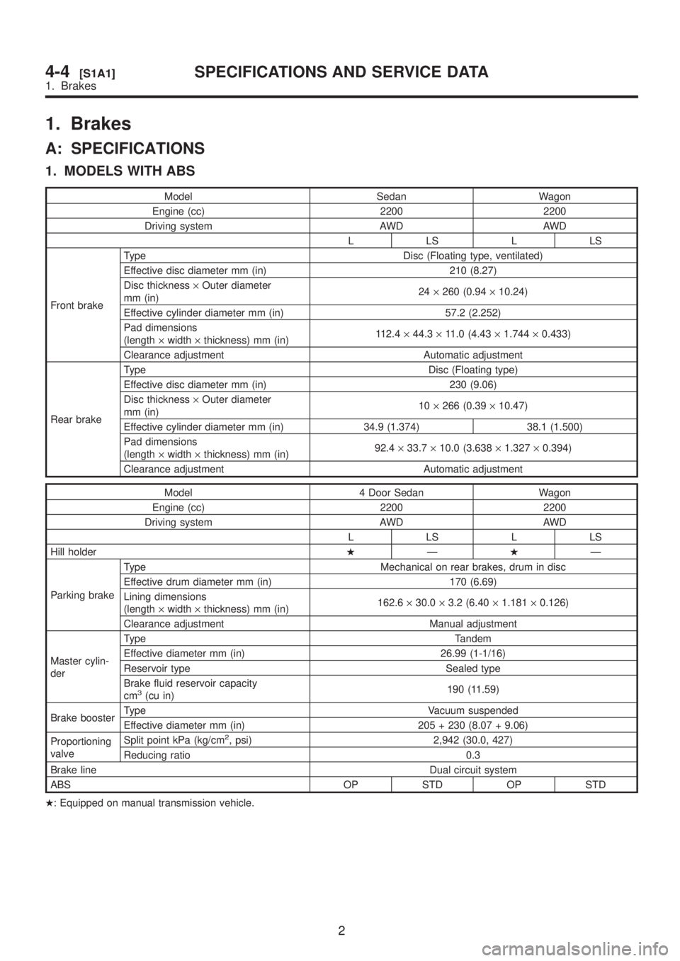
1. Brakes
A: SPECIFICATIONS
1. MODELS WITH ABS
Model Sedan Wagon
Engine (cc) 2200 2200
Driving system AWD AWD
LLSLLS
Front brakeType Disc (Floating type, ventilated)
Effective disc diameter mm (in) 210 (8.27)
Disc thickness´Outer diameter
mm (in)24´260 (0.94´10.24)
Effective cylinder diameter mm (in) 57.2 (2.252)
Pad dimensions
(length´width´thickness) mm (in)112.4´44.3´11.0 (4.43´1.744´0.433)
Clearance adjustment Automatic adjustment
Rear brakeType Disc (Floating type)
Effective disc diameter mm (in) 230 (9.06)
Disc thickness´Outer diameter
mm (in)10´266 (0.39´10.47)
Effective cylinder diameter mm (in) 34.9 (1.374) 38.1 (1.500)
Pad dimensions
(length´width´thickness) mm (in)92.4´33.7´10.0 (3.638´1.327´0.394)
Clearance adjustment Automatic adjustment
Model 4 Door Sedan Wagon
Engine (cc) 2200 2200
Driving system AWD AWD
LLSLLS
Hill holderHÐHÐ
Parking brakeType Mechanical on rear brakes, drum in disc
Effective drum diameter mm (in) 170 (6.69)
Lining dimensions
(length´width´thickness) mm (in)162.6´30.0´3.2 (6.40´1.181´0.126)
Clearance adjustment Manual adjustment
Master cylin-
derType Tandem
Effective diameter mm (in) 26.99 (1-1/16)
Reservoir type Sealed type
Brake fluid reservoir capacity
cm
3(cu in)190 (11.59)
Brake boosterType Vacuum suspended
Effective diameter mm (in) 205 + 230 (8.07 + 9.06)
Proportioning
valveSplit point kPa (kg/cm
2, psi) 2,942 (30.0, 427)
Reducing ratio 0.3
Brake lineDual circuit system
ABS OP STD OP STD
H: Equipped on manual transmission vehicle.
2
4-4[S1A1]SPECIFICATIONS AND SERVICE DATA
1. Brakes
Page 874 of 1456
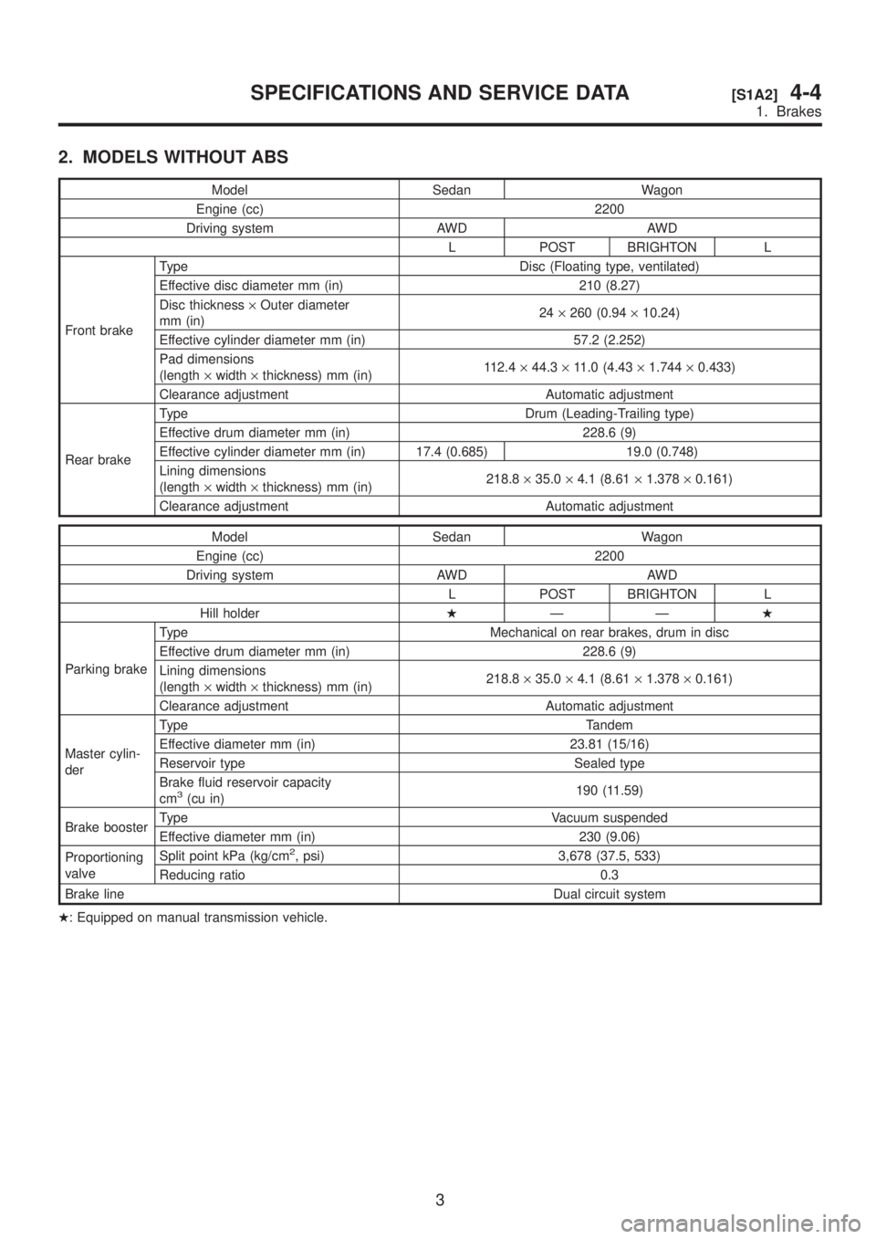
2. MODELS WITHOUT ABS
Model Sedan Wagon
Engine (cc) 2200
Driving system AWD AWD
L POST BRIGHTON L
Front brakeType Disc (Floating type, ventilated)
Effective disc diameter mm (in) 210 (8.27)
Disc thickness´Outer diameter
mm (in)24´260 (0.94´10.24)
Effective cylinder diameter mm (in) 57.2 (2.252)
Pad dimensions
(length´width´thickness) mm (in)112.4´44.3´11.0 (4.43´1.744´0.433)
Clearance adjustment Automatic adjustment
Rear brakeType Drum (Leading-Trailing type)
Effective drum diameter mm (in) 228.6 (9)
Effective cylinder diameter mm (in) 17.4 (0.685) 19.0 (0.748)
Lining dimensions
(length´width´thickness) mm (in)218.8´35.0´4.1 (8.61´1.378´0.161)
Clearance adjustment Automatic adjustment
Model Sedan Wagon
Engine (cc) 2200
Driving system AWD AWD
L POST BRIGHTON L
Hill holderHÐÐH
Parking brakeType Mechanical on rear brakes, drum in disc
Effective drum diameter mm (in) 228.6 (9)
Lining dimensions
(length´width´thickness) mm (in)218.8´35.0´4.1 (8.61´1.378´0.161)
Clearance adjustment Automatic adjustment
Master cylin-
derType Tandem
Effective diameter mm (in) 23.81 (15/16)
Reservoir type Sealed type
Brake fluid reservoir capacity
cm
3(cu in)190 (11.59)
Brake boosterType Vacuum suspended
Effective diameter mm (in) 230 (9.06)
Proportioning
valveSplit point kPa (kg/cm
2, psi) 3,678 (37.5, 533)
Reducing ratio 0.3
Brake lineDual circuit system
H: Equipped on manual transmission vehicle.
3
[S1A2]4-4SPECIFICATIONS AND SERVICE DATA
1. Brakes
Page 875 of 1456
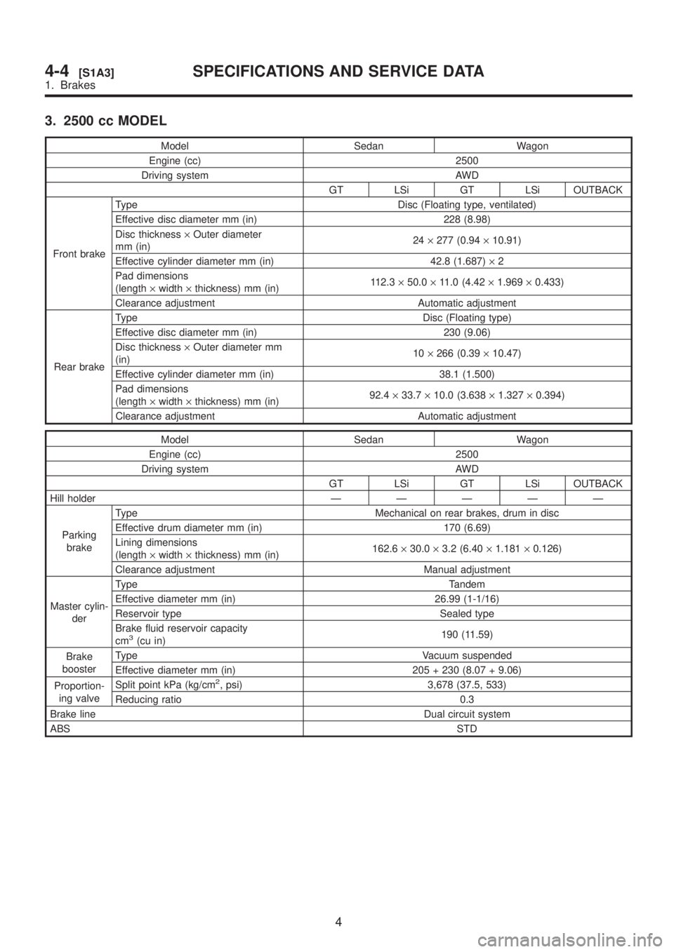
3. 2500 cc MODEL
Model Sedan Wagon
Engine (cc) 2500
Driving system AWD
GT LSi GT LSi OUTBACK
Front brakeType Disc (Floating type, ventilated)
Effective disc diameter mm (in) 228 (8.98)
Disc thickness´Outer diameter
mm (in)24´277 (0.94´10.91)
Effective cylinder diameter mm (in) 42.8 (1.687)´2
Pad dimensions
(length´width´thickness) mm (in)112.3´50.0´11.0 (4.42´1.969´0.433)
Clearance adjustment Automatic adjustment
Rear brakeType Disc (Floating type)
Effective disc diameter mm (in) 230 (9.06)
Disc thickness´Outer diameter mm
(in)10´266 (0.39´10.47)
Effective cylinder diameter mm (in) 38.1 (1.500)
Pad dimensions
(length´width´thickness) mm (in)92.4´33.7´10.0 (3.638´1.327´0.394)
Clearance adjustment Automatic adjustment
Model Sedan Wagon
Engine (cc) 2500
Driving system AWD
GT LSi GT LSi OUTBACK
Hill holderÐÐÐÐÐ
Parking
brakeType Mechanical on rear brakes, drum in disc
Effective drum diameter mm (in) 170 (6.69)
Lining dimensions
(length´width´thickness) mm (in)162.6´30.0´3.2 (6.40´1.181´0.126)
Clearance adjustment Manual adjustment
Master cylin-
derType Tandem
Effective diameter mm (in) 26.99 (1-1/16)
Reservoir type Sealed type
Brake fluid reservoir capacity
cm
3(cu in)190 (11.59)
Brake
boosterType Vacuum suspended
Effective diameter mm (in) 205 + 230 (8.07 + 9.06)
Proportion-
ing valveSplit point kPa (kg/cm
2, psi) 3,678 (37.5, 533)
Reducing ratio 0.3
Brake lineDual circuit system
ABSSTD
4
4-4[S1A3]SPECIFICATIONS AND SERVICE DATA
1. Brakes
Page 876 of 1456
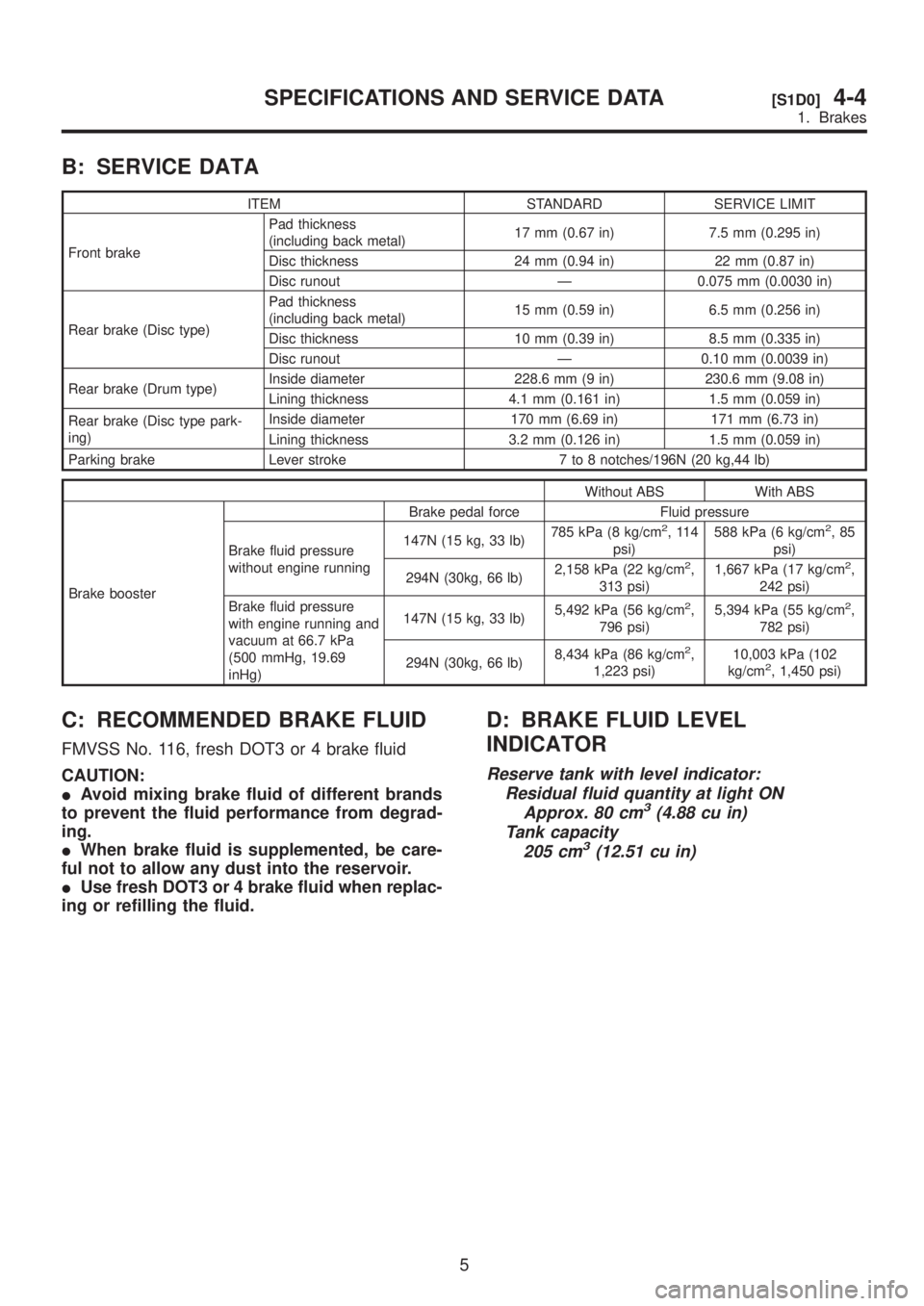
B: SERVICE DATA
ITEM STANDARD SERVICE LIMIT
Front brakePad thickness
(including back metal)17 mm (0.67 in) 7.5 mm (0.295 in)
Disc thickness 24 mm (0.94 in) 22 mm (0.87 in)
Disc runout Ð 0.075 mm (0.0030 in)
Rear brake (Disc type)Pad thickness
(including back metal)15 mm (0.59 in) 6.5 mm (0.256 in)
Disc thickness 10 mm (0.39 in) 8.5 mm (0.335 in)
Disc runout Ð 0.10 mm (0.0039 in)
Rear brake (Drum type)Inside diameter 228.6 mm (9 in) 230.6 mm (9.08 in)
Lining thickness 4.1 mm (0.161 in) 1.5 mm (0.059 in)
Rear brake (Disc type park-
ing)Inside diameter 170 mm (6.69 in) 171 mm (6.73 in)
Lining thickness 3.2 mm (0.126 in) 1.5 mm (0.059 in)
Parking brake Lever stroke 7 to 8 notches/196N (20 kg,44 lb)
Without ABS With ABS
Brake boosterBrake pedal force Fluid pressure
Brake fluid pressure
without engine running147N (15 kg, 33 lb)785 kPa (8 kg/cm
2,114
psi)588 kPa (6 kg/cm2,85
psi)
294N (30kg, 66 lb)2,158 kPa (22 kg/cm
2,
313 psi)1,667 kPa (17 kg/cm2,
242 psi)
Brake fluid pressure
with engine running and
vacuum at 66.7 kPa
(500 mmHg, 19.69
inHg)147N (15 kg, 33 lb)5,492 kPa (56 kg/cm
2,
796 psi)5,394 kPa (55 kg/cm2,
782 psi)
294N (30kg, 66 lb)8,434 kPa (86 kg/cm
2,
1,223 psi)10,003 kPa (102
kg/cm2, 1,450 psi)
C: RECOMMENDED BRAKE FLUID
FMVSS No. 116, fresh DOT3 or 4 brake fluid
CAUTION:
IAvoid mixing brake fluid of different brands
to prevent the fluid performance from degrad-
ing.
IWhen brake fluid is supplemented, be care-
ful not to allow any dust into the reservoir.
IUse fresh DOT3 or 4 brake fluid when replac-
ing or refilling the fluid.
D: BRAKE FLUID LEVEL
INDICATOR
Reserve tank with level indicator:
Residual fluid quantity at light ON
Approx. 80 cm
3(4.88 cu in)
Tank capacity
205 cm
3(12.51 cu in)
5
[S1D0]4-4SPECIFICATIONS AND SERVICE DATA
1. Brakes