stop start SUBARU LEGACY 1999 Service Repair Manual
[x] Cancel search | Manufacturer: SUBARU, Model Year: 1999, Model line: LEGACY, Model: SUBARU LEGACY 1999Pages: 1456, PDF Size: 59.93 MB
Page 35 of 1456
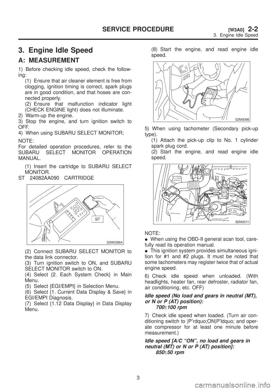
3. Engine Idle Speed
A: MEASUREMENT
1) Before checking idle speed, check the follow-
ing:
(1) Ensure that air cleaner element is free from
clogging, ignition timing is correct, spark plugs
are in good condition, and that hoses are con-
nected properly.
(2) Ensure that malfunction indicator light
(CHECK ENGINE light) does not illuminate.
2) Warm-up the engine.
3) Stop the engine, and turn ignition switch to
OFF.
4) When using SUBARU SELECT MONITOR;
NOTE:
For detailed operation procedures, refer to the
SUBARU SELECT MONITOR OPERATION
MANUAL.
(1) Insert the cartridge to SUBARU SELECT
MONITOR.
ST 24082AA090 CARTRIDGE
S2M0286A
(2) Connect SUBARU SELECT MONITOR to
the data link connector.
(3) Turn ignition switch to ON, and SUBARU
SELECT MONITOR switch to ON.
(4) Select {2. Each System Check} in Main
Menu.
(5) Select {EGI/EMPI} in Selection Menu.
(6) Select {1. Current Data Display & Save} in
EGI/EMPI Diagnosis.
(7) Select {1.12 Data Display} in Data Display
Menu.(8) Start the engine, and read engine idle
speed.
S2M0098
5) When using tachometer (Secondary pick-up
type).
(1) Attach the pick-up clip to No. 1 cylinder
spark plug cord.
(2) Start the engine, and read engine idle
speed.
B2M2011
NOTE:
IWhen using the OBD-II general scan tool, care-
fully read its operation manual.
IThis ignition system provides simultaneous igni-
tion for #1 and #2 plugs. It must be noted that
some tachometers may register twice that of actual
engine speed.
6) Check idle speed when unloaded. (With
headlights, heater fan, rear defroster, radiator fan,
air conditioning, etc. OFF)
Idle speed (No load and gears in neutral (MT),
or N or P (AT) position):
700
±100 rpm
7) Check idle speed when loaded. (Turn air con-
ditioning switch to |P¢rdquo;ON|P'ldquo; and oper-
ate compressor for at least one minute before
measurement.)
Idle speed [A/C ªONº, no load and gears in
neutral (MT) or N or P (AT) position]:
850
±50 rpm
3
[W3A0]2-2SERVICE PROCEDURE
3. Engine Idle Speed
Page 40 of 1456
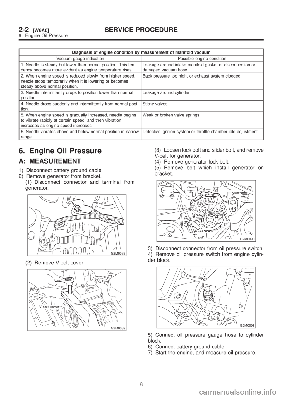
Diagnosis of engine condition by measurement of manifold vacuum
Vacuum gauge indication Possible engine condition
1. Needle is steady but lower than normal position. This ten-
dency becomes more evident as engine temperature rises.Leakage around intake manifold gasket or disconnection or
damaged vacuum hose
2. When engine speed is reduced slowly from higher speed,
needle stops temporarily when it is lowering or becomes
steady above normal position.Back pressure too high, or exhaust system clogged
3. Needle intermittently drops to position lower than normal
position.Leakage around cylinder
4. Needle drops suddenly and intermittently from normal posi-
tion.Sticky valves
5. When engine speed is gradually increased, needle begins
to vibrate rapidly at certain speed, and then vibration
increases as engine speed increases.Weak or broken valve springs
6. Needle vibrates above and below normal position in narrow
range.Defective ignition system or throttle chamber idle adjustment
6. Engine Oil Pressure
A: MEASUREMENT
1) Disconnect battery ground cable.
2) Remove generator from bracket.
(1) Disconnect connector and terminal from
generator.
G2M0088
(2) Remove V-belt cover
G2M0089
(3) Loosen lock bolt and slider bolt, and remove
V-belt for generator.
(4) Remove generator lock bolt.
(5) Remove bolt which install generator on
bracket.
G2M0090
3) Disconnect connector from oil pressure switch.
4) Remove oil pressure switch from engine cylin-
der block.
G2M0091
5) Connect oil pressure gauge hose to cylinder
block.
6) Connect battery ground cable.
7) Start the engine, and measure oil pressure.
6
2-2[W6A0]SERVICE PROCEDURE
6. Engine Oil Pressure
Page 41 of 1456
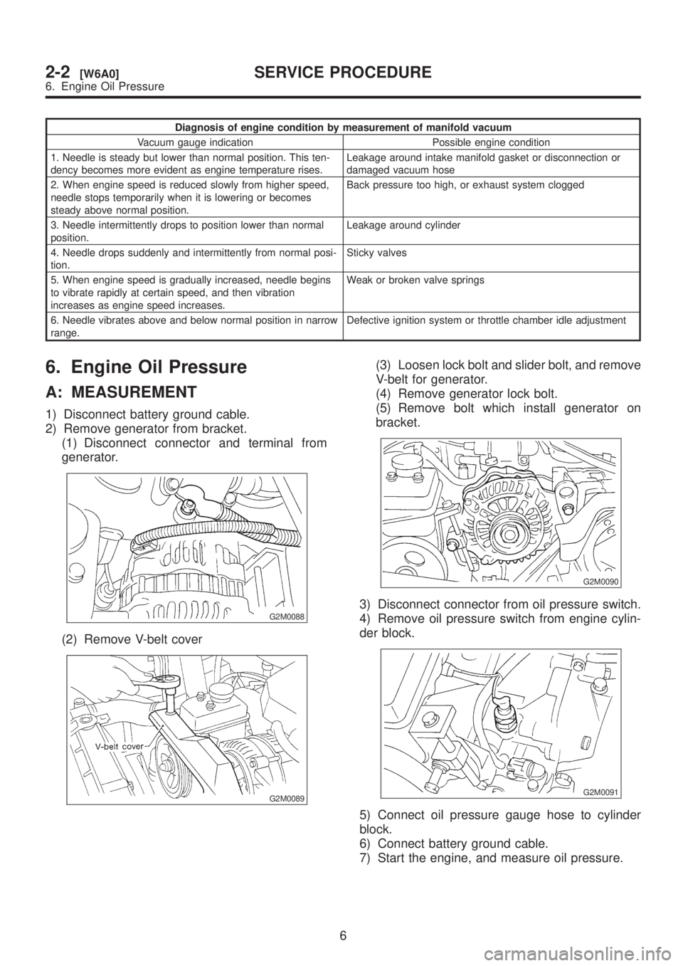
Diagnosis of engine condition by measurement of manifold vacuum
Vacuum gauge indication Possible engine condition
1. Needle is steady but lower than normal position. This ten-
dency becomes more evident as engine temperature rises.Leakage around intake manifold gasket or disconnection or
damaged vacuum hose
2. When engine speed is reduced slowly from higher speed,
needle stops temporarily when it is lowering or becomes
steady above normal position.Back pressure too high, or exhaust system clogged
3. Needle intermittently drops to position lower than normal
position.Leakage around cylinder
4. Needle drops suddenly and intermittently from normal posi-
tion.Sticky valves
5. When engine speed is gradually increased, needle begins
to vibrate rapidly at certain speed, and then vibration
increases as engine speed increases.Weak or broken valve springs
6. Needle vibrates above and below normal position in narrow
range.Defective ignition system or throttle chamber idle adjustment
6. Engine Oil Pressure
A: MEASUREMENT
1) Disconnect battery ground cable.
2) Remove generator from bracket.
(1) Disconnect connector and terminal from
generator.
G2M0088
(2) Remove V-belt cover
G2M0089
(3) Loosen lock bolt and slider bolt, and remove
V-belt for generator.
(4) Remove generator lock bolt.
(5) Remove bolt which install generator on
bracket.
G2M0090
3) Disconnect connector from oil pressure switch.
4) Remove oil pressure switch from engine cylin-
der block.
G2M0091
5) Connect oil pressure gauge hose to cylinder
block.
6) Connect battery ground cable.
7) Start the engine, and measure oil pressure.
6
2-2[W6A0]SERVICE PROCEDURE
6. Engine Oil Pressure
Page 430 of 1456
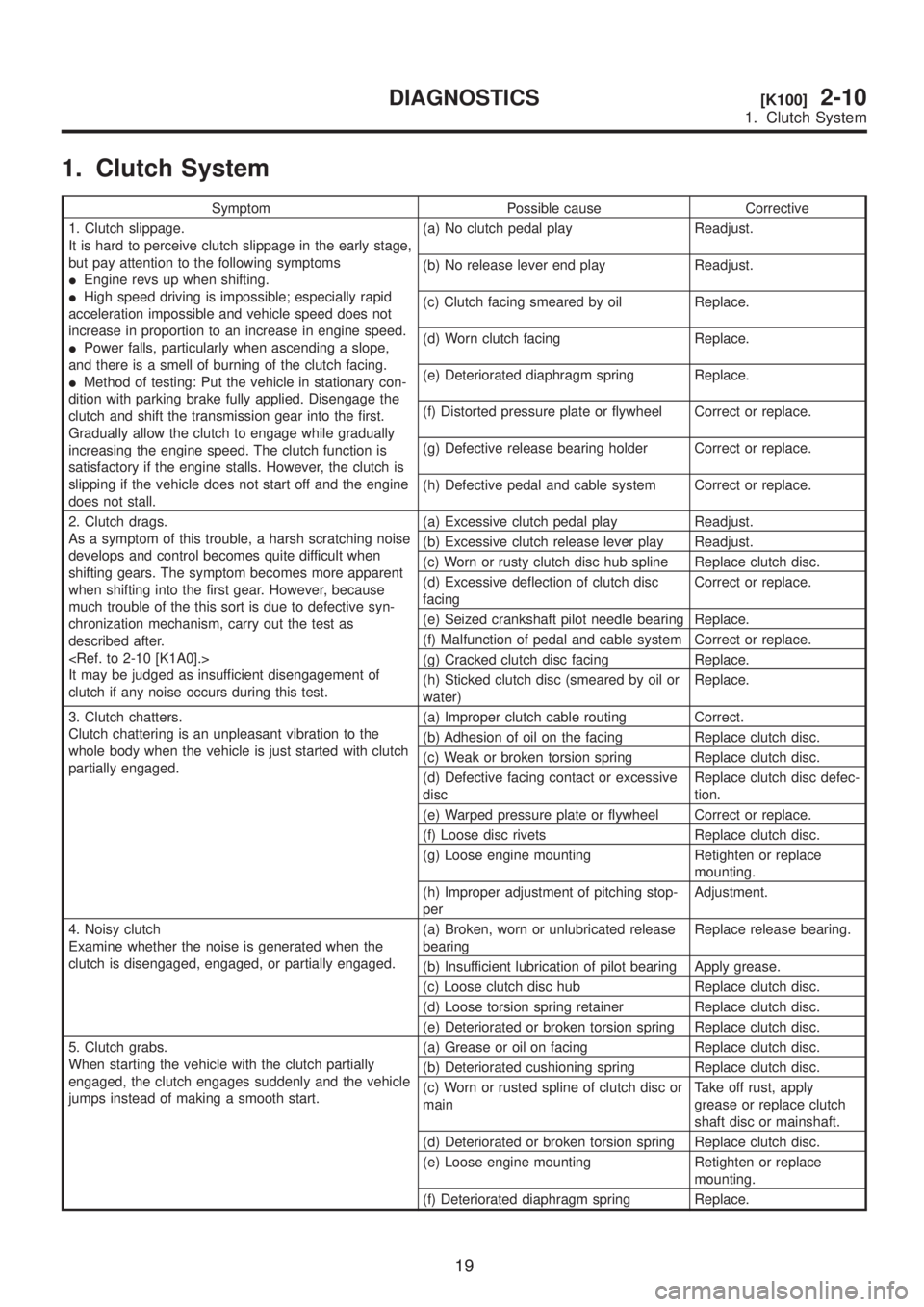
1. Clutch System
Symptom Possible cause Corrective
1. Clutch slippage.
It is hard to perceive clutch slippage in the early stage,
but pay attention to the following symptoms
IEngine revs up when shifting.
IHigh speed driving is impossible; especially rapid
acceleration impossible and vehicle speed does not
increase in proportion to an increase in engine speed.
IPower falls, particularly when ascending a slope,
and there is a smell of burning of the clutch facing.
IMethod of testing: Put the vehicle in stationary con-
dition with parking brake fully applied. Disengage the
clutch and shift the transmission gear into the first.
Gradually allow the clutch to engage while gradually
increasing the engine speed. The clutch function is
satisfactory if the engine stalls. However, the clutch is
slipping if the vehicle does not start off and the engine
does not stall.(a) No clutch pedal play Readjust.
(b) No release lever end play Readjust.
(c) Clutch facing smeared by oil Replace.
(d) Worn clutch facing Replace.
(e) Deteriorated diaphragm spring Replace.
(f) Distorted pressure plate or flywheel Correct or replace.
(g) Defective release bearing holder Correct or replace.
(h) Defective pedal and cable system Correct or replace.
2. Clutch drags.
As a symptom of this trouble, a harsh scratching noise
develops and control becomes quite difficult when
shifting gears. The symptom becomes more apparent
when shifting into the first gear. However, because
much trouble of the this sort is due to defective syn-
chronization mechanism, carry out the test as
described after.
It may be judged as insufficient disengagement of
clutch if any noise occurs during this test.(a) Excessive clutch pedal play Readjust.
(b) Excessive clutch release lever play Readjust.
(c) Worn or rusty clutch disc hub spline Replace clutch disc.
(d) Excessive deflection of clutch disc
facingCorrect or replace.
(e) Seized crankshaft pilot needle bearing Replace.
(f) Malfunction of pedal and cable system Correct or replace.
(g) Cracked clutch disc facing Replace.
(h) Sticked clutch disc (smeared by oil or
water)Replace.
3. Clutch chatters.
Clutch chattering is an unpleasant vibration to the
whole body when the vehicle is just started with clutch
partially engaged.(a) Improper clutch cable routing Correct.
(b) Adhesion of oil on the facing Replace clutch disc.
(c) Weak or broken torsion spring Replace clutch disc.
(d) Defective facing contact or excessive
discReplace clutch disc defec-
tion.
(e) Warped pressure plate or flywheel Correct or replace.
(f) Loose disc rivets Replace clutch disc.
(g) Loose engine mounting Retighten or replace
mounting.
(h) Improper adjustment of pitching stop-
perAdjustment.
4. Noisy clutch
Examine whether the noise is generated when the
clutch is disengaged, engaged, or partially engaged.(a) Broken, worn or unlubricated release
bearingReplace release bearing.
(b) Insufficient lubrication of pilot bearing Apply grease.
(c) Loose clutch disc hub Replace clutch disc.
(d) Loose torsion spring retainer Replace clutch disc.
(e) Deteriorated or broken torsion spring Replace clutch disc.
5. Clutch grabs.
When starting the vehicle with the clutch partially
engaged, the clutch engages suddenly and the vehicle
jumps instead of making a smooth start.(a) Grease or oil on facing Replace clutch disc.
(b) Deteriorated cushioning spring Replace clutch disc.
(c) Worn or rusted spline of clutch disc or
mainTake off rust, apply
grease or replace clutch
shaft disc or mainshaft.
(d) Deteriorated or broken torsion spring Replace clutch disc.
(e) Loose engine mounting Retighten or replace
mounting.
(f) Deteriorated diaphragm spring Replace.
19
[K100]2-10DIAGNOSTICS
1. Clutch System
Page 454 of 1456
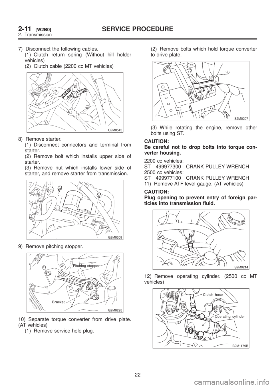
7) Disconnect the following cables.
(1) Clutch return spring (Without hill holder
vehicles)
(2) Clutch cable (2200 cc MT vehicles)
G2M0545
8) Remove starter.
(1) Disconnect connectors and terminal from
starter.
(2) Remove bolt which installs upper side of
starter.
(3) Remove nut which installs lower side of
starter, and remove starter from transmission.
G2M0309
9) Remove pitching stopper.
G2M0295
10) Separate torque converter from drive plate.
(AT vehicles)
(1) Remove service hole plug.(2) Remove bolts which hold torque converter
to drive plate.
S2M0207
(3) While rotating the engine, remove other
bolts using ST.
CAUTION:
Be careful not to drop bolts into torque con-
verter housing.
2200 cc vehicles:
ST 499977300 CRANK PULLEY WRENCH
2500 cc vehicles:
ST 499977100 CRANK PULLEY WRENCH
11) Remove ATF level gauge. (AT vehicles)
CAUTION:
Plug opening to prevent entry of foreign par-
ticles into transmission fluid.
S2M0214
12) Remove operating cylinder. (2500 cc MT
vehicles)
B2M1179B
22
2-11[W2B0]SERVICE PROCEDURE
2. Transmission
Page 502 of 1456
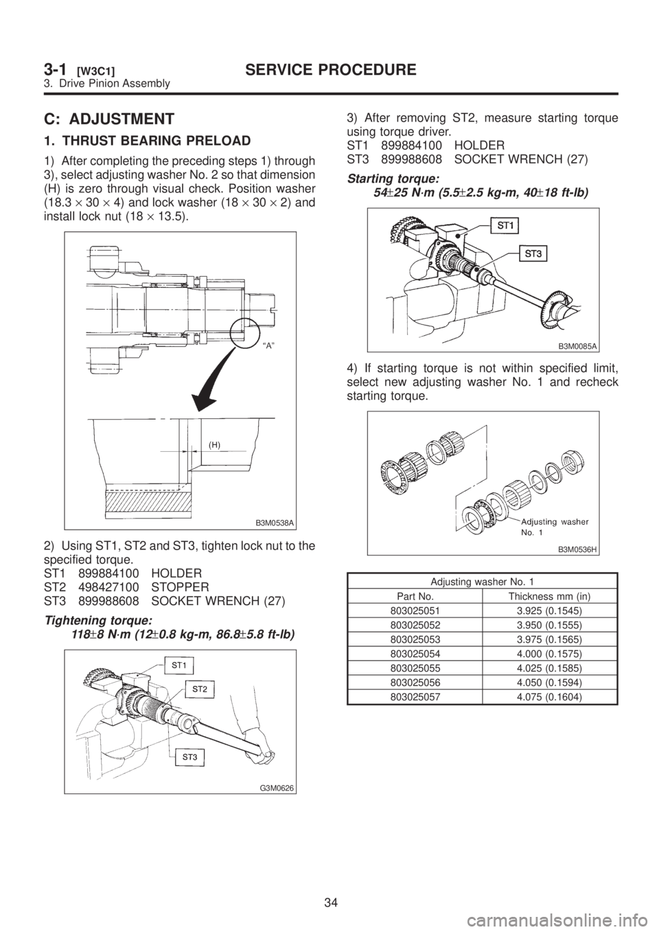
C: ADJUSTMENT
1. THRUST BEARING PRELOAD
1) After completing the preceding steps 1) through
3), select adjusting washer No. 2 so that dimension
(H) is zero through visual check. Position washer
(18.3´30´4) and lock washer (18´30´2) and
install lock nut (18´13.5).
B3M0538A
2) Using ST1, ST2 and ST3, tighten lock nut to the
specified torque.
ST1 899884100 HOLDER
ST2 498427100 STOPPER
ST3 899988608 SOCKET WRENCH (27)
Tightening torque:
11 8
±8 N´m (12±0.8 kg-m, 86.8±5.8 ft-lb)
G3M0626
3) After removing ST2, measure starting torque
using torque driver.
ST1 899884100 HOLDER
ST3 899988608 SOCKET WRENCH (27)
Starting torque:
54
±25 N´m (5.5±2.5 kg-m, 40±18 ft-lb)
B3M0085A
4) If starting torque is not within specified limit,
select new adjusting washer No. 1 and recheck
starting torque.
B3M0536H
Adjusting washer No. 1
Part No. Thickness mm (in)
803025051 3.925 (0.1545)
803025052 3.950 (0.1555)
803025053 3.975 (0.1565)
803025054 4.000 (0.1575)
803025055 4.025 (0.1585)
803025056 4.050 (0.1594)
803025057 4.075 (0.1604)
34
3-1[W3C1]SERVICE PROCEDURE
3. Drive Pinion Assembly
Page 503 of 1456
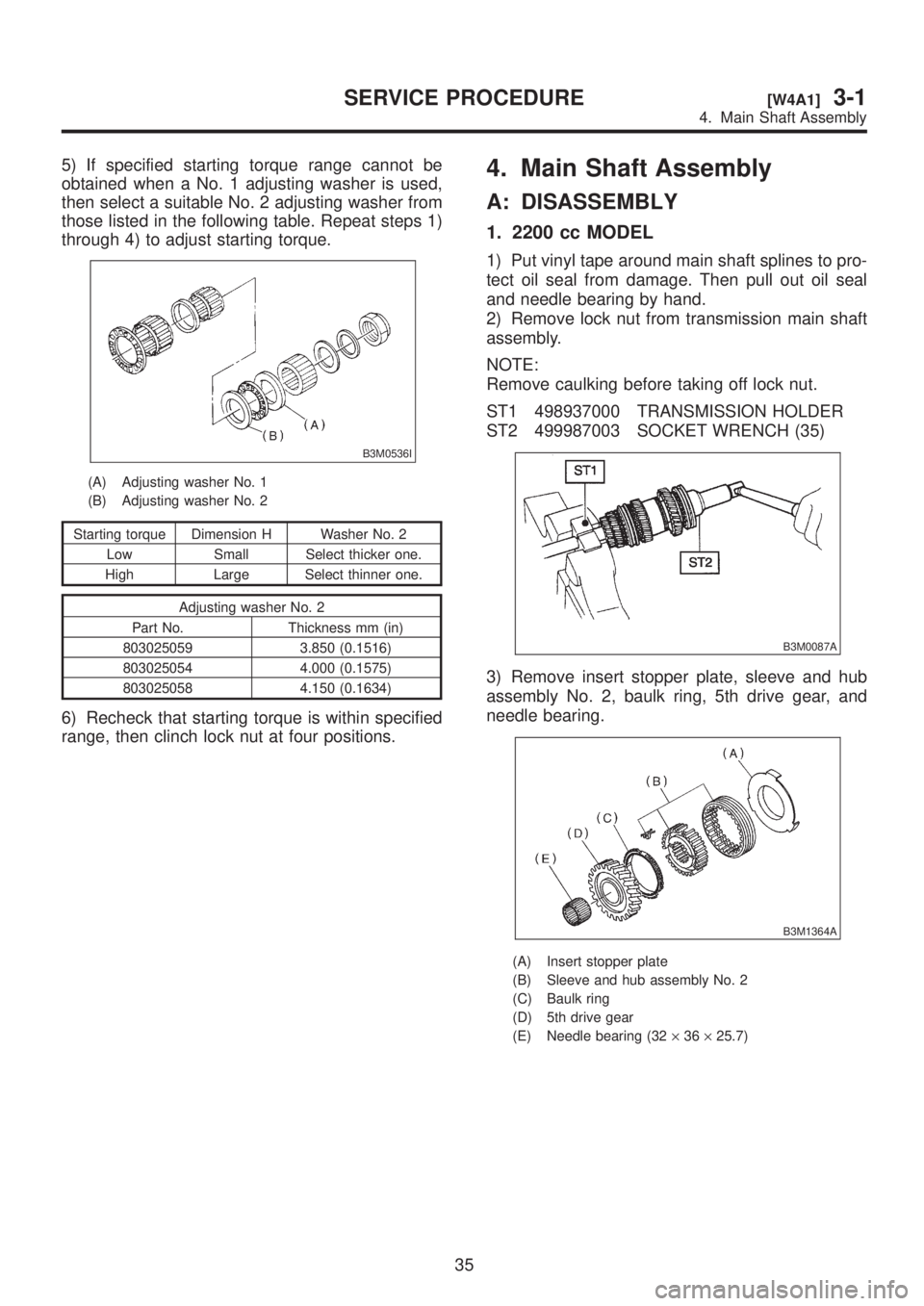
5) If specified starting torque range cannot be
obtained when a No. 1 adjusting washer is used,
then select a suitable No. 2 adjusting washer from
those listed in the following table. Repeat steps 1)
through 4) to adjust starting torque.
B3M0536I
(A) Adjusting washer No. 1
(B) Adjusting washer No. 2
Starting torque Dimension H Washer No. 2
Low Small Select thicker one.
High Large Select thinner one.
Adjusting washer No. 2
Part No. Thickness mm (in)
803025059 3.850 (0.1516)
803025054 4.000 (0.1575)
803025058 4.150 (0.1634)
6) Recheck that starting torque is within specified
range, then clinch lock nut at four positions.
4. Main Shaft Assembly
A: DISASSEMBLY
1. 2200 cc MODEL
1) Put vinyl tape around main shaft splines to pro-
tect oil seal from damage. Then pull out oil seal
and needle bearing by hand.
2) Remove lock nut from transmission main shaft
assembly.
NOTE:
Remove caulking before taking off lock nut.
ST1 498937000 TRANSMISSION HOLDER
ST2 499987003 SOCKET WRENCH (35)
B3M0087A
3) Remove insert stopper plate, sleeve and hub
assembly No. 2, baulk ring, 5th drive gear, and
needle bearing.
B3M1364A
(A) Insert stopper plate
(B) Sleeve and hub assembly No. 2
(C) Baulk ring
(D) 5th drive gear
(E) Needle bearing (32´36´25.7)
35
[W4A1]3-1SERVICE PROCEDURE
4. Main Shaft Assembly
Page 506 of 1456
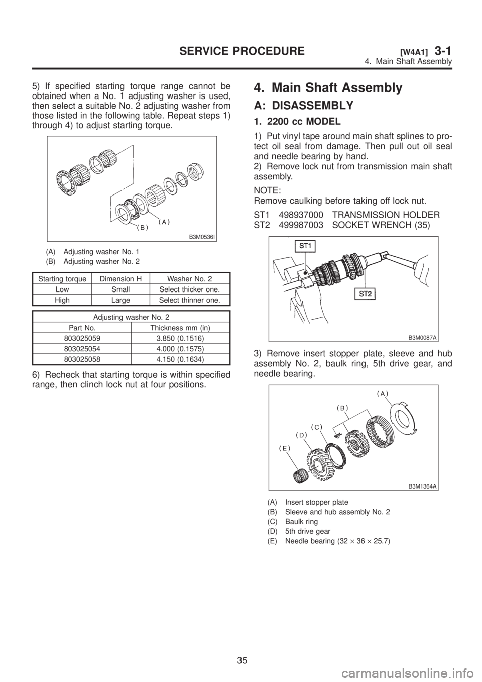
5) If specified starting torque range cannot be
obtained when a No. 1 adjusting washer is used,
then select a suitable No. 2 adjusting washer from
those listed in the following table. Repeat steps 1)
through 4) to adjust starting torque.
B3M0536I
(A) Adjusting washer No. 1
(B) Adjusting washer No. 2
Starting torque Dimension H Washer No. 2
Low Small Select thicker one.
High Large Select thinner one.
Adjusting washer No. 2
Part No. Thickness mm (in)
803025059 3.850 (0.1516)
803025054 4.000 (0.1575)
803025058 4.150 (0.1634)
6) Recheck that starting torque is within specified
range, then clinch lock nut at four positions.
4. Main Shaft Assembly
A: DISASSEMBLY
1. 2200 cc MODEL
1) Put vinyl tape around main shaft splines to pro-
tect oil seal from damage. Then pull out oil seal
and needle bearing by hand.
2) Remove lock nut from transmission main shaft
assembly.
NOTE:
Remove caulking before taking off lock nut.
ST1 498937000 TRANSMISSION HOLDER
ST2 499987003 SOCKET WRENCH (35)
B3M0087A
3) Remove insert stopper plate, sleeve and hub
assembly No. 2, baulk ring, 5th drive gear, and
needle bearing.
B3M1364A
(A) Insert stopper plate
(B) Sleeve and hub assembly No. 2
(C) Baulk ring
(D) 5th drive gear
(E) Needle bearing (32´36´25.7)
35
[W4A1]3-1SERVICE PROCEDURE
4. Main Shaft Assembly
Page 555 of 1456
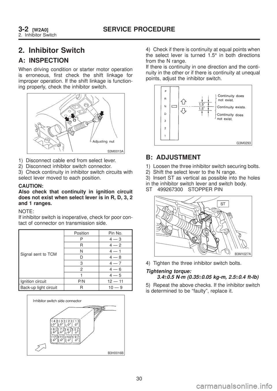
2. Inhibitor Switch
A: INSPECTION
When driving condition or starter motor operation
is erroneous, first check the shift linkage for
improper operation. If the shift linkage is function-
ing properly, check the inhibitor switch.
S3M0013A
1) Disconnect cable end from select lever.
2) Disconnect inhibitor switch connector.
3) Check continuity in inhibitor switch circuits with
select lever moved to each position.
CAUTION:
Also check that continuity in ignition circuit
does not exist when select lever is in R, D, 3, 2
and 1 ranges.
NOTE:
If inhibitor switch is inoperative, check for poor con-
tact of connector on transmission side.
Signal sent to TCMPosition Pin No.
P 4Ð3
R 4Ð2
N 4Ð1
D 4Ð8
3 4Ð7
2 4Ð6
1 4Ð5
Ignition circuit P/N 12 Ð 11
Back-up light circuit R 10 Ð 9
B3H0016B
4) Check if there is continuity at equal points when
the select lever is turned 1.5É in both directions
from the N range.
If there is continuity in one direction and the conti-
nuity in the other or if there is continuity at unequal
points, adjust the inhibitor switch.
G3M0293
B: ADJUSTMENT
1) Loosen the three inhibitor switch securing bolts.
2) Shift the select lever to the N range.
3) Insert ST as vertical as possible into the holes
in the inhibitor switch lever and switch body.
ST 499267300 STOPPER PIN
B3M1027A
4) Tighten the three inhibitor switch bolts.
Tightening torque:
3.4
±0.5 N´m (0.35±0.05 kg-m, 2.5±0.4 ft-lb)
5) Repeat the above checks. If the inhibitor switch
is determined to be ªfaultyº, replace it.
30
3-2[W2A0]SERVICE PROCEDURE
2. Inhibitor Switch
Page 571 of 1456
8. Time Lag Test
A: INSPECTION
1. GENERAL INFORMATION
If the shift lever is shifted while the engine is idling,
there will be a certain time elapse or lag before the
shock can be felt. This is used for checking the
condition of the low clutch, reverse clutch, low &
reverse brake and one-way clutch.
CAUTION:
IPerform the test at normal operation fluid
temperature 60 to 80ÉC (140 to 176ÉF).
IBe sure to allow a one minute interval
between tests.
IMake three measurements and take the aver-
age value.
2. TEST METHODS
1) Fully apply the parking brake.
2) Start the engine.
Check idling speed (A/C OFF).
ªNº range: 800±100 rpm
3) Shift the shift lever from ªNº to ªDº range.
Using a stop watch, measure the time it takes from
shifting the lever until the shock is felt.
Time lag: Less than 1.2 seconds
4) In same manner, measure the time lag for ªNº
®ªRº.
Time lag: Less than 1.5 seconds
3. EVALUATION
1) If ªNº®ªDº time lag is longer than specified:
ILine pressure too low
ILow clutch worn
IOne-way clutch not operating properly
2) If ªNº®ªRº time lag is longer than specified:
ILine pressure too low
IReverse clutch worn
ILow & reverse brake worn
9. Line Pressure Test
A: MEASUREMENT
1. GENERAL INFORMATION
If the clutch or the brake shows a sign of slippage
or shifting sensation is not correct, the line pres-
sure should be checked.
IExcessive shocks during upshifting or shifting
takes place at a higher point than under normal
circumstances, may be due to the line pressure
being too high.
ISlippage or inability to operate the vehicle may,
in most cases, be due to loss of oil pressure for the
operation of the clutch, brake or control valve.
1) Line pressure measurement (under no load)
CAUTION:
IBefore measuring line pressure, jack-up all
wheels.
IMaintain temperature of ATF at approxi-
mately 50ÉC (122ÉF) during measurement.
(ATF will reach the above temperature after
idling the engine for approximately 30 minutes
with select lever in ªNº or ªPº.)
2) Line pressure measurement (under heavy load)
CAUTION:
IBefore measuring line pressure, apply both
foot and parking brakes with all wheels
chocked (Same as for ªstallº test conditions).
IMeasure line pressure when select lever is in
ªRº, ª2º with engine under stall conditions.
IMeasure line pressure within 5 seconds after
shifting the select lever to each position. (If line
pressure needs to be measured again, allow
the engine to idle and then stop. Wait for at
least one minute before measurement.)
IMaintain the temperature of ATF at approxi-
mately 50ÉC (122ÉF) during measurement. (ATF
will reach the above temperature after idling
the engine for approximately 30 minutes with
the select lever in ªNº or ªPº.)
43
[W9A1]3-2SERVICE PROCEDURE
9. Line Pressure Test