brake SUBARU LEGACY 1999 Service Service Manual
[x] Cancel search | Manufacturer: SUBARU, Model Year: 1999, Model line: LEGACY, Model: SUBARU LEGACY 1999Pages: 1456, PDF Size: 59.93 MB
Page 580 of 1456
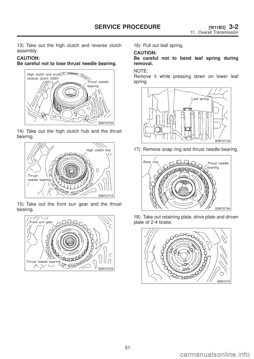
13) Take out the high clutch and reverse clutch
assembly.
CAUTION:
Be careful not to lose thrust needle bearing.
B3M1070A
14) Take out the high clutch hub and the thrust
bearing.
B3M1071A
15) Take out the front sun gear and the thrust
bearing.
B3M1072A
16) Pull out leaf spring.
CAUTION:
Be careful not to bend leaf spring during
removal.
NOTE:
Remove it while pressing down on lower leaf
spring.
B3M1073A
17) Remove snap ring and thrust needle bearing.
B3M1074A
18) Take out retaining plate, drive plate and driven
plate of 2-4 brake.
B3M1075
51
[W11B3]3-2SERVICE PROCEDURE
11. Overall Transmission
Page 581 of 1456
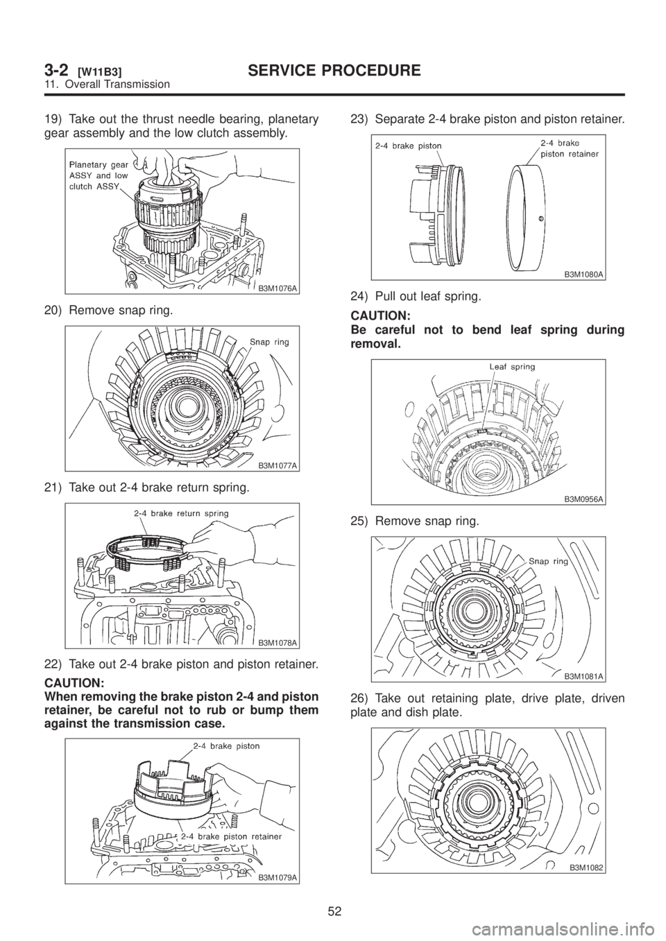
19) Take out the thrust needle bearing, planetary
gear assembly and the low clutch assembly.
B3M1076A
20) Remove snap ring.
B3M1077A
21) Take out 2-4 brake return spring.
B3M1078A
22) Take out 2-4 brake piston and piston retainer.
CAUTION:
When removing the brake piston 2-4 and piston
retainer, be careful not to rub or bump them
against the transmission case.
B3M1079A
23) Separate 2-4 brake piston and piston retainer.
B3M1080A
24) Pull out leaf spring.
CAUTION:
Be careful not to bend leaf spring during
removal.
B3M0956A
25) Remove snap ring.
B3M1081A
26) Take out retaining plate, drive plate, driven
plate and dish plate.
B3M1082
52
3-2[W11B3]SERVICE PROCEDURE
11. Overall Transmission
Page 582 of 1456
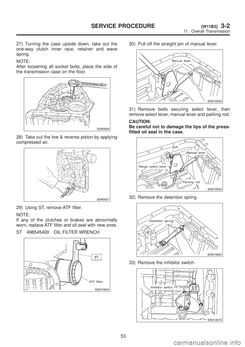
27) Turning the case upside down, take out the
one-way clutch inner race, retainer and wave
spring.
NOTE:
After loosening all socket bolts, place the side of
the transmission case on the floor.
B3M0958
28) Take out the low & reverse piston by applying
compressed air.
B3M0957
29) Using ST, remove ATF filter.
NOTE:
If any of the clutches or brakes are abnormally
worn, replace ATF filter and oil seal with new ones.
ST 498545400 OIL FILTER WRENCH
B3M1084A
30) Pull off the straight pin of manual lever.
B3M1083A
31) Remove bolts securing select lever, then
remove select lever, manual lever and parking rod.
CAUTION:
Be careful not to damage the lips of the press-
fitted oil seal in the case.
B3M1085A
32) Remove the detention spring.
B3M1086A
33) Remove the inhibitor switch.
B3M1087A
53
[W11B3]3-2SERVICE PROCEDURE
11. Overall Transmission
Page 591 of 1456
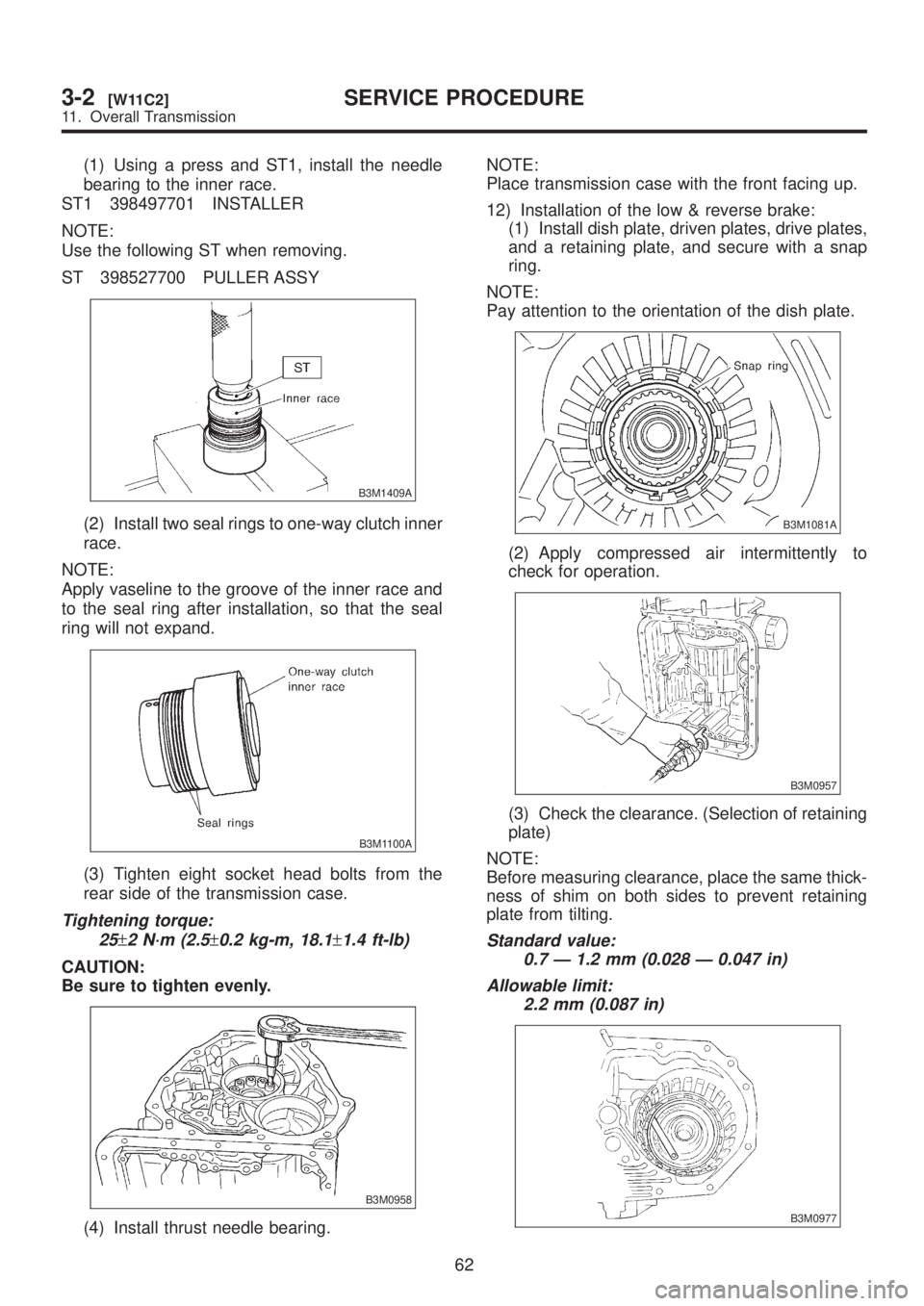
(1) Using a press and ST1, install the needle
bearing to the inner race.
ST1 398497701 INSTALLER
NOTE:
Use the following ST when removing.
ST 398527700 PULLER ASSY
B3M1409A
(2) Install two seal rings to one-way clutch inner
race.
NOTE:
Apply vaseline to the groove of the inner race and
to the seal ring after installation, so that the seal
ring will not expand.
B3M1100A
(3) Tighten eight socket head bolts from the
rear side of the transmission case.
Tightening torque:
25
±2 N´m (2.5±0.2 kg-m, 18.1±1.4 ft-lb)
CAUTION:
Be sure to tighten evenly.
B3M0958
(4) Install thrust needle bearing.NOTE:
Place transmission case with the front facing up.
12) Installation of the low & reverse brake:
(1) Install dish plate, driven plates, drive plates,
and a retaining plate, and secure with a snap
ring.
NOTE:
Pay attention to the orientation of the dish plate.
B3M1081A
(2) Apply compressed air intermittently to
check for operation.
B3M0957
(3) Check the clearance. (Selection of retaining
plate)
NOTE:
Before measuring clearance, place the same thick-
ness of shim on both sides to prevent retaining
plate from tilting.
Standard value:
0.7 Ð 1.2 mm (0.028 Ð 0.047 in)
Allowable limit:
2.2 mm (0.087 in)
B3M0977
62
3-2[W11C2]SERVICE PROCEDURE
11. Overall Transmission
Page 592 of 1456
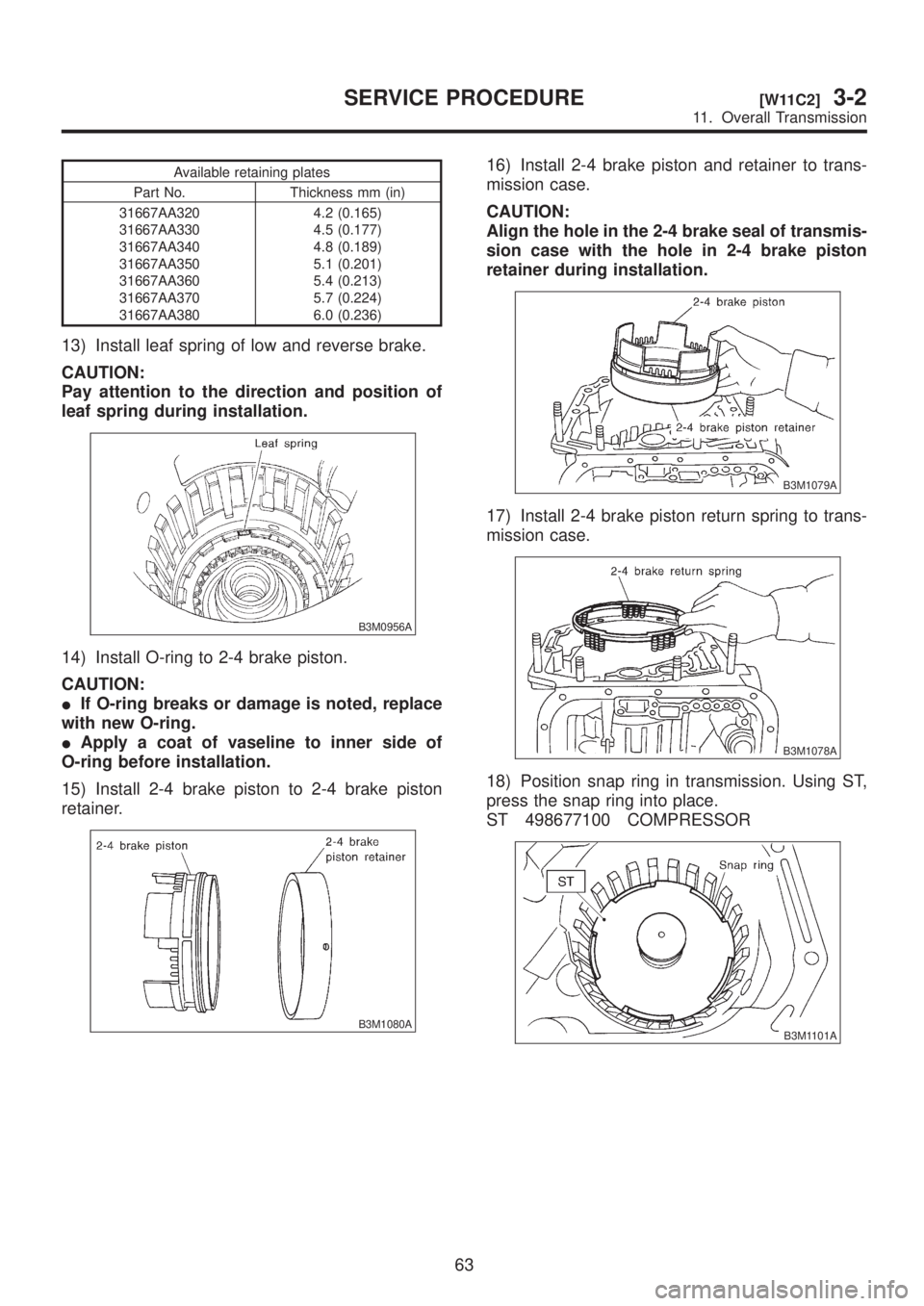
Available retaining plates
Part No. Thickness mm (in)
31667AA320
31667AA330
31667AA340
31667AA350
31667AA360
31667AA370
31667AA3804.2 (0.165)
4.5 (0.177)
4.8 (0.189)
5.1 (0.201)
5.4 (0.213)
5.7 (0.224)
6.0 (0.236)
13) Install leaf spring of low and reverse brake.
CAUTION:
Pay attention to the direction and position of
leaf spring during installation.
B3M0956A
14) Install O-ring to 2-4 brake piston.
CAUTION:
IIf O-ring breaks or damage is noted, replace
with new O-ring.
IApply a coat of vaseline to inner side of
O-ring before installation.
15) Install 2-4 brake piston to 2-4 brake piston
retainer.
B3M1080A
16) Install 2-4 brake piston and retainer to trans-
mission case.
CAUTION:
Align the hole in the 2-4 brake seal of transmis-
sion case with the hole in 2-4 brake piston
retainer during installation.
B3M1079A
17) Install 2-4 brake piston return spring to trans-
mission case.
B3M1078A
18) Position snap ring in transmission. Using ST,
press the snap ring into place.
ST 498677100 COMPRESSOR
B3M1101A
63
[W11C2]3-2SERVICE PROCEDURE
11. Overall Transmission
Page 593 of 1456
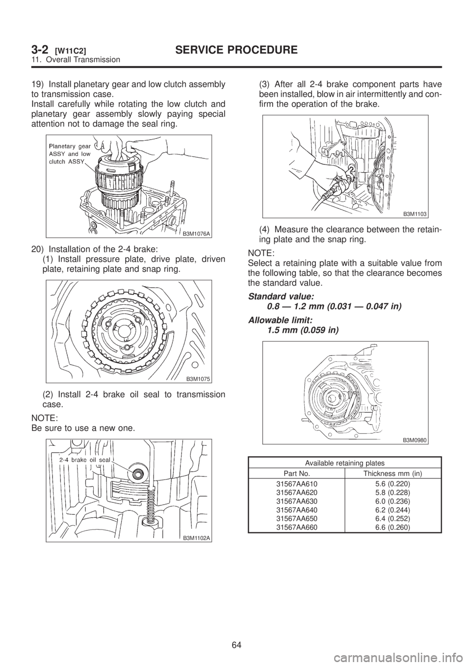
19) Install planetary gear and low clutch assembly
to transmission case.
Install carefully while rotating the low clutch and
planetary gear assembly slowly paying special
attention not to damage the seal ring.
B3M1076A
20) Installation of the 2-4 brake:
(1) Install pressure plate, drive plate, driven
plate, retaining plate and snap ring.
B3M1075
(2) Install 2-4 brake oil seal to transmission
case.
NOTE:
Be sure to use a new one.
B3M1102A
(3) After all 2-4 brake component parts have
been installed, blow in air intermittently and con-
firm the operation of the brake.
B3M1103
(4) Measure the clearance between the retain-
ing plate and the snap ring.
NOTE:
Select a retaining plate with a suitable value from
the following table, so that the clearance becomes
the standard value.
Standard value:
0.8 Ð 1.2 mm (0.031 Ð 0.047 in)
Allowable limit:
1.5 mm (0.059 in)
B3M0980
Available retaining plates
Part No. Thickness mm (in)
31567AA610
31567AA620
31567AA630
31567AA640
31567AA650
31567AA6605.6 (0.220)
5.8 (0.228)
6.0 (0.236)
6.2 (0.244)
6.4 (0.252)
6.6 (0.260)
64
3-2[W11C2]SERVICE PROCEDURE
11. Overall Transmission
Page 594 of 1456
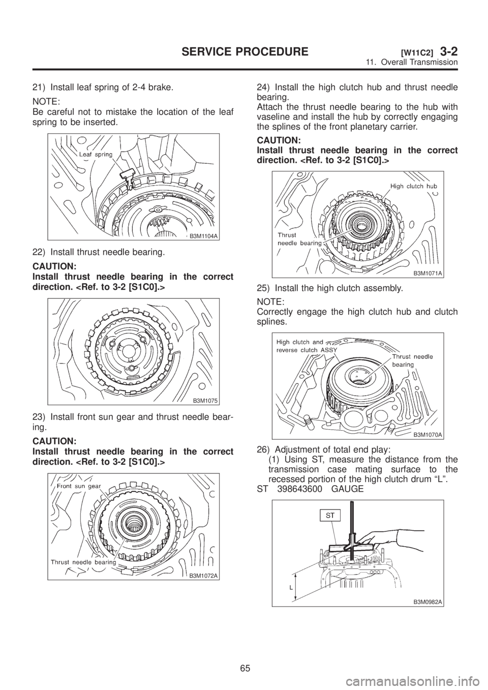
21) Install leaf spring of 2-4 brake.
NOTE:
Be careful not to mistake the location of the leaf
spring to be inserted.
B3M1104A
22) Install thrust needle bearing.
CAUTION:
Install thrust needle bearing in the correct
direction.
B3M1075
23) Install front sun gear and thrust needle bear-
ing.
CAUTION:
Install thrust needle bearing in the correct
direction.
B3M1072A
24) Install the high clutch hub and thrust needle
bearing.
Attach the thrust needle bearing to the hub with
vaseline and install the hub by correctly engaging
the splines of the front planetary carrier.
CAUTION:
Install thrust needle bearing in the correct
direction.
B3M1071A
25) Install the high clutch assembly.
NOTE:
Correctly engage the high clutch hub and clutch
splines.
B3M1070A
26) Adjustment of total end play:
(1) Using ST, measure the distance from the
transmission case mating surface to the
recessed portion of the high clutch drum ªLº.
ST 398643600 GAUGE
B3M0982A
65
[W11C2]3-2SERVICE PROCEDURE
11. Overall Transmission
Page 596 of 1456
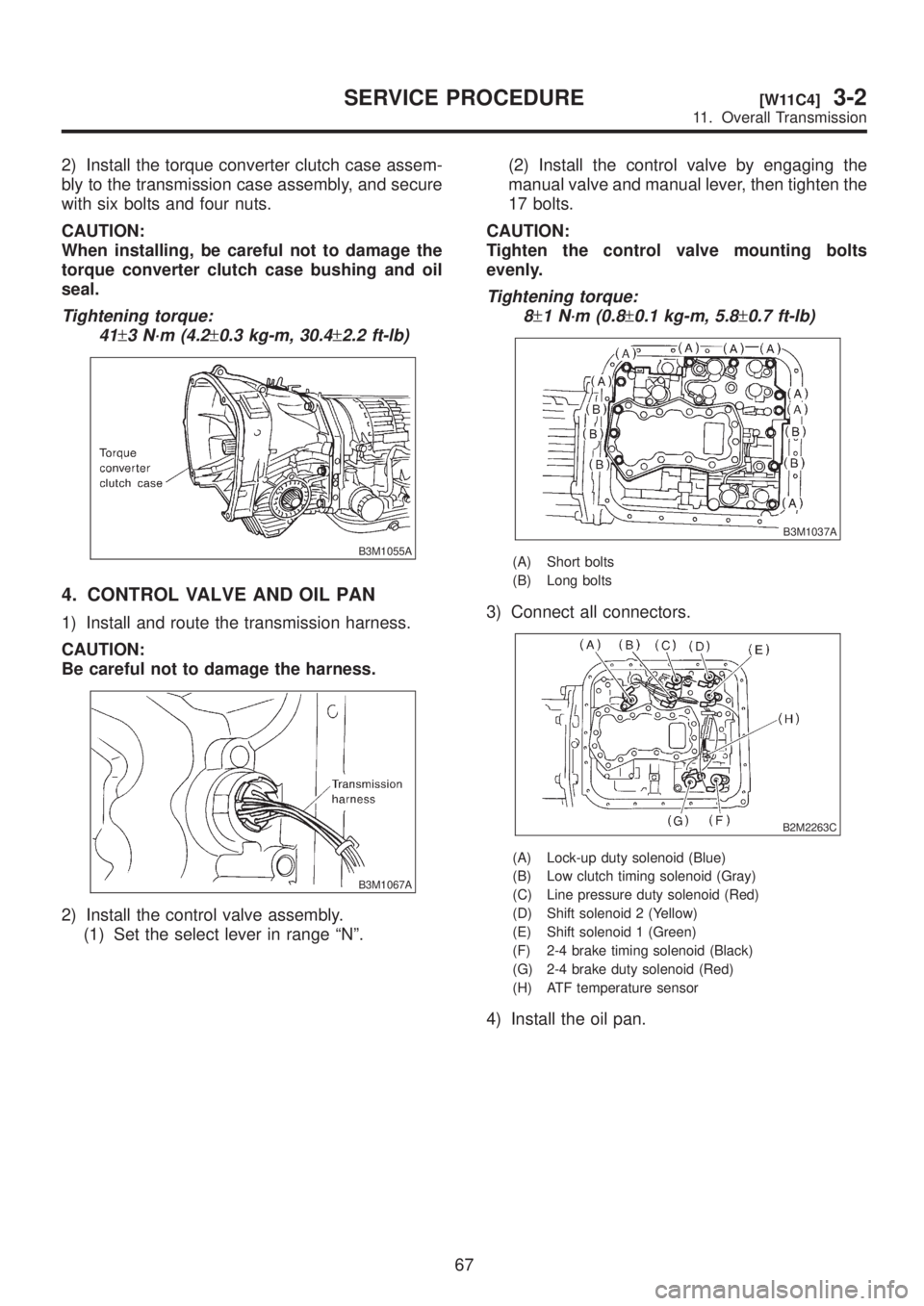
2) Install the torque converter clutch case assem-
bly to the transmission case assembly, and secure
with six bolts and four nuts.
CAUTION:
When installing, be careful not to damage the
torque converter clutch case bushing and oil
seal.
Tightening torque:
41
±3 N´m (4.2±0.3 kg-m, 30.4±2.2 ft-lb)
B3M1055A
4. CONTROL VALVE AND OIL PAN
1) Install and route the transmission harness.
CAUTION:
Be careful not to damage the harness.
B3M1067A
2) Install the control valve assembly.
(1) Set the select lever in range ªNº.(2) Install the control valve by engaging the
manual valve and manual lever, then tighten the
17 bolts.
CAUTION:
Tighten the control valve mounting bolts
evenly.
Tightening torque:
8
±1 N´m (0.8±0.1 kg-m, 5.8±0.7 ft-lb)
B3M1037A
(A) Short bolts
(B) Long bolts
3) Connect all connectors.
B2M2263C
(A) Lock-up duty solenoid (Blue)
(B) Low clutch timing solenoid (Gray)
(C) Line pressure duty solenoid (Red)
(D) Shift solenoid 2 (Yellow)
(E) Shift solenoid 1 (Green)
(F) 2-4 brake timing solenoid (Black)
(G) 2-4 brake duty solenoid (Red)
(H) ATF temperature sensor
4) Install the oil pan.
67
[W11C4]3-2SERVICE PROCEDURE
11. Overall Transmission
Page 605 of 1456
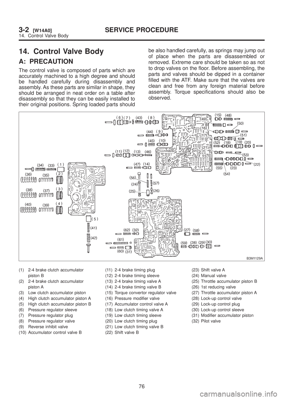
14. Control Valve Body
A: PRECAUTION
The control valve is composed of parts which are
accurately machined to a high degree and should
be handled carefully during disassembly and
assembly. As these parts are similar in shape, they
should be arranged in neat order on a table after
disassembly so that they can be easily installed to
their original positions. Spring loaded parts shouldbe also handled carefully, as springs may jump out
of place when the parts are disassembled or
removed. Extreme care should be taken so as not
to drop valves on the floor. Before assembling, the
parts and valves should be dipped in a container
filled with the ATF. Make sure that the valves are
clean and free from any foreign material before
assembly. Torque specifications should also be
observed.
B3M1129A
(1) 2-4 brake clutch accumulator
piston B
(2) 2-4 brake clutch accumulator
piston A
(3) Low clutch accumulator piston
(4) High clutch accumulator piston A
(5) High clutch accumulator piston B
(6) Pressure regulator sleeve
(7) Pressure regulator plug
(8) Pressure regulator valve
(9) Reverse inhibit valve
(10) Accumulator control valve B(11) 2-4 brake timing plug
(12) 2-4 brake timing sleeve
(13) 2-4 brake timing valve A
(14) 2-4 brake timing valve B
(15) Torque convertor regulator valve
(16) Pressure modifier valve
(17) Accumulator control valve A
(18) Low clutch timing valve A
(19) Low clutch timing sleeve
(20) Low clutch timing plug
(21) Low clutch timing valve B
(22) Shift valve B(23) Shift valve A
(24) Manual valve
(25) Throttle accumulator piston B
(26) 1st reducing valve
(27) Throttle accumulator piston A
(28) Lock-up control valve
(29) Lock-up control plug
(30) Lock-up control sleeve
(31) Modifier accumulator piston
(32) Pilot valve
76
3-2[W14A0]SERVICE PROCEDURE
14. Control Valve Body
Page 606 of 1456
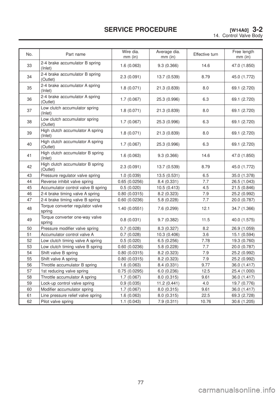
No. Part nameWire dia.
mm (in)Average dia.
mm (in)Effective turnFree length
mm (in)
332-4 brake accumulator B spring
(Inlet)1.6 (0.063) 9.3 (0.366) 14.6 47.0 (1.850)
342-4 brake accumulator B spring
(Outlet)2.3 (0.091) 13.7 (0.539) 8.79 45.0 (1.772)
352-4 brake accumulator A spring
(Inlet)1.8 (0.071) 21.3 (0.839) 8.0 69.1 (2.720)
362-4 brake accumulator A spring
(Outlet)1.7 (0.067) 25.3 (0.996) 6.3 69.1 (2.720)
37Low clutch accumulator spring
(Inlet)1.8 (0.071) 21.3 (0.839) 8.0 69.1 (2.720)
38Low clutch accumulator spring
(Outlet)1.7 (0.067) 25.3 (0.996) 6.3 69.1 (2.720)
39High clutch accumulator A spring
(Inlet)1.8 (0.071) 21.3 (0.839) 8.0 69.1 (2.720)
40High clutch accumulator A spring
(Outlet)1.7 (0.067) 25.3 (0.996) 6.3 69.1 (2.720)
41High clutch accumulator B spring
(Inlet)1.6 (0.063) 9.3 (0.366) 14.6 47.0 (1.850)
42High clutch accumulator B spring
(Outlet)2.3 (0.091) 13.7 (0.539) 8.79 45.0 (1.772)
43 Pressure regulator valve spring 1.0 (0.039) 13.5 (0.531) 6.5 35.0 (1.378)
44 Reverse inhibit valve spring 0.65 (0.0256) 8.4 (0.331) 7.7 26.5 (1.043)
45 Accumulator control valve B spring 0.5 (0.020) 10.5 (0.413) 4.5 21.5 (0.846)
46 2-4 brake timing valve A spring 0.80 (0.0315) 8.2 (0.323) 7.9 25.2 (0.992)
47 2-4 brake timing valve B spring 0.60 (0.0236) 5.8 (0.228) 7.7 20.0 (0.787)
48Torque converter regulator valve
spring1.40 (0.0551) 7.6 (0.299) 12.1 34.7 (1.366)
49Torque converter one-way valve
spring0.8 (0.031) 9.7 (0.382) 11.5 40.0 (1.575)
50 Pressure modifier valve spring 0.7 (0.028) 8.3 (0.327) 8.2 26.9 (1.059)
51 Accumulator control valve A 0.7 (0.028) 10.3 (0.406) 3.6 15.1 (0.594)
52 Low clutch timing valve A spring 0.5 (0.020) 6.5 (0.256) 7.78 19.3 (0.760)
53 Low clutch timing valve B spring 0.60 (0.0236) 5.8 (0.228) 7.7 20.0 (0.787)
54 Shift valve B spring 0.80 (0.0315) 8.2 (0.323) 7.9 25.2 (0.992)
55 Shift valve A spring 0.80 (0.0315) 8.2 (0.323) 7.9 25.2 (0.992)
56 Throttle accumulator B spring 1.6 (0.063) 8.4 (0.331) 9.77 36.0 (1.417)
57 1st reducing valve spring 0.75 (0.0295) 6.0 (0.236) 12.5 25.4 (1.000)
58 Throttle accumulator A spring 1.7 (0.067) 8.0 (0.315) 9.61 36.0 (1.417)
59 Lock-up control valve spring 0.9 (0.035) 11.2 (0.441) 4.0 19.7 (0.776)
60 Modifier accumulator spring 1.7 (0.067) 8.0 (0.315) 9.61 36.0 (1.417)
61 Line pressure relief valve spring 1.6 (0.063) 8.0 (0.315) 22.5 69.3 (2.728)
62 Pilot valve spring 1.1 (0.043) 7.9 (0.311) 10.76 30.6 (1.205)
77
[W14A0]3-2SERVICE PROCEDURE
14. Control Valve Body