ECO mode SUBARU LEGACY 1999 Service Repair Manual
[x] Cancel search | Manufacturer: SUBARU, Model Year: 1999, Model line: LEGACY, Model: SUBARU LEGACY 1999Pages: 1456, PDF Size: 59.93 MB
Page 33 of 1456
1. Foreword
A: GENERAL
This chapter describes major inspection and ser-
vice procedures for the engine mounted on the
body. For procedures not found in this chapter,
refer to the service procedure section in the appli-
cable chapter.
2. Ignition Timing
A: MEASUREMENT
CAUTION:
After warming-up, engine becomes very hot.
Be careful not to burn yourself during mea-
surement.
1) Warm-up the engine.
2) To check the ignition timing, connect a timing
light to #1 cylinder spark plug cord, and illuminate
the timing mark with the timing light.
3) Start the engine at idle speed and check the
ignition timing.
Ignition timing [BTDC/rpm]:
2200 cc California spec. vehicles
15É
±8É/700
2200 cc except California spec. vehicles
10É
±8É/700 (MT model)
15É
±8É/700 (AT model)
2500 cc model
15É
±8É/700
B2M2010
If the timing is not correct, check the ignition con-
trol system.
2
2-2[W1A0]SERVICE PROCEDURE
1. Foreword
Page 34 of 1456
1. Foreword
A: GENERAL
This chapter describes major inspection and ser-
vice procedures for the engine mounted on the
body. For procedures not found in this chapter,
refer to the service procedure section in the appli-
cable chapter.
2. Ignition Timing
A: MEASUREMENT
CAUTION:
After warming-up, engine becomes very hot.
Be careful not to burn yourself during mea-
surement.
1) Warm-up the engine.
2) To check the ignition timing, connect a timing
light to #1 cylinder spark plug cord, and illuminate
the timing mark with the timing light.
3) Start the engine at idle speed and check the
ignition timing.
Ignition timing [BTDC/rpm]:
2200 cc California spec. vehicles
15É
±8É/700
2200 cc except California spec. vehicles
10É
±8É/700 (MT model)
15É
±8É/700 (AT model)
2500 cc model
15É
±8É/700
B2M2010
If the timing is not correct, check the ignition con-
trol system.
2
2-2[W1A0]SERVICE PROCEDURE
1. Foreword
Page 38 of 1456
2. 2500 cc MODEL
CAUTION:
After warming-up, engine becomes very hot.
Be careful not to burn yourself during mea-
surement.
1) After warming-up the engine, turn ignition
switch to OFF.
2) Make sure that the battery is fully charged.
3) Remove all the spark plugs.
4) Disconnect connectors from fuel injectors.
5) Fully open throttle valve.
6) Check the starter motor for satisfactory perfor-
mance and operation.
7) Hold the compression gauge tight against the
spark plug hole.
CAUTION:
When using a screw-in type compression
gauge, the screw (put into cylinder head spark
plug hole) should be less than 18 mm (0.71 in)
long.
8) Crank the engine by means of the starter motor,
and read the maximum value on the gauge when
the pointer is steady.
B2M0752A
9) Perform at least two measurements per
cylinder, and make sure that the values are correct.
Compression (350 rpm and fully open
throttle):
Standard;
1,216 kPa (12.4 kg/cm
2, 176 psi)
Limit;
941 kPa (9.6 kg/cm
2, 137 psi)
Difference between cylinders;
49 kPa (0.5 kg/cm
2, 7 psi), or less
5. Intake Manifold Vacuum
A: MEASUREMENT
1) Warm-up the engine.
2) Disconnect the brake vacuum hose and install
the vacuum gauge to the hose fitting on the mani-
fold.
3) Keep the engine at the idle speed and read the
vacuum gauge indication.
By observing the gauge needle movement, the
internal condition of the engine can be diagnosed
as described below.
H2M1601
Vacuum pressure (at idling, A/C ªOFFº):
Less than þ60.0 kPa (þ450 mmHg, þ17.72
inHg)
5
[W5A0]2-2SERVICE PROCEDURE
5. Intake Manifold Vacuum
Page 39 of 1456
2. 2500 cc MODEL
CAUTION:
After warming-up, engine becomes very hot.
Be careful not to burn yourself during mea-
surement.
1) After warming-up the engine, turn ignition
switch to OFF.
2) Make sure that the battery is fully charged.
3) Remove all the spark plugs.
4) Disconnect connectors from fuel injectors.
5) Fully open throttle valve.
6) Check the starter motor for satisfactory perfor-
mance and operation.
7) Hold the compression gauge tight against the
spark plug hole.
CAUTION:
When using a screw-in type compression
gauge, the screw (put into cylinder head spark
plug hole) should be less than 18 mm (0.71 in)
long.
8) Crank the engine by means of the starter motor,
and read the maximum value on the gauge when
the pointer is steady.
B2M0752A
9) Perform at least two measurements per
cylinder, and make sure that the values are correct.
Compression (350 rpm and fully open
throttle):
Standard;
1,216 kPa (12.4 kg/cm
2, 176 psi)
Limit;
941 kPa (9.6 kg/cm
2, 137 psi)
Difference between cylinders;
49 kPa (0.5 kg/cm
2, 7 psi), or less
5. Intake Manifold Vacuum
A: MEASUREMENT
1) Warm-up the engine.
2) Disconnect the brake vacuum hose and install
the vacuum gauge to the hose fitting on the mani-
fold.
3) Keep the engine at the idle speed and read the
vacuum gauge indication.
By observing the gauge needle movement, the
internal condition of the engine can be diagnosed
as described below.
H2M1601
Vacuum pressure (at idling, A/C ªOFFº):
Less than þ60.0 kPa (þ450 mmHg, þ17.72
inHg)
5
[W5A0]2-2SERVICE PROCEDURE
5. Intake Manifold Vacuum
Page 50 of 1456
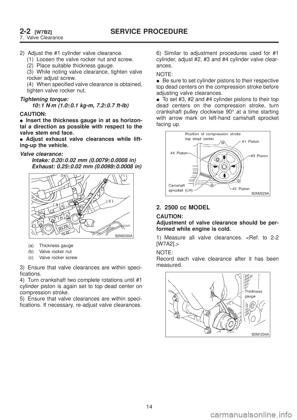
2) Adjust the #1 cylinder valve clearance.
(1) Loosen the valve rocker nut and screw.
(2) Place suitable thickness gauge.
(3) While noting valve clearance, tighten valve
rocker adjust screw.
(4) When specified valve clearance is obtained,
tighten valve rocker nut.
Tightening torque:
10
±1 N´m (1.0±0.1 kg-m, 7.2±0.7 ft-lb)
CAUTION:
IInsert the thickness gauge in at as horizon-
tal a direction as possible with respect to the
valve stem end face.
IAdjust exhaust valve clearances while lift-
ing-up the vehicle.
Valve clearance:
Intake: 0.20
±0.02 mm (0.0079±0.0008 in)
Exhaust: 0.25
±0.02 mm (0.0098±0.0008 in)
B2M2030A
(a) Thickness gauge
(b) Valve rocker nut
(c) Valve rocker screw
3) Ensure that valve clearances are within speci-
fications.
4) Turn crankshaft two complete rotations until #1
cylinder piston is again set to top dead center on
compression stroke.
5) Ensure that valve clearances are within speci-
fications. If necessary, re-adjust valve clearances.6) Similar to adjustment procedures used for #1
cylinder, adjust #2, #3 and #4 cylinder valve clear-
ances.
NOTE:
IBe sure to set cylinder pistons to their respective
top dead centers on the compression stroke before
adjusting valve clearances.
ITo set #3, #2 and #4 cylinder pistons to their top
dead centers on the compression stroke, turn
crankshaft pulley clockwise 90É at a time starting
with arrow mark on left-hand camshaft sprocket
facing up.
B2M2029A
2. 2500 cc MODEL
CAUTION:
Adjustment of valve clearance should be per-
formed while engine is cold.
1) Measure all valve clearances.
NOTE:
Record each valve clearance after it has been
measured.
B2M1234A
14
2-2[W7B2]SERVICE PROCEDURE
7. Valve Clearance
Page 415 of 1456
1. General
A: PRECAUTION
When servicing clutch system, pay attention to the
following items.
1. MECHANICAL APPLICATION TYPE
1) Check the routing of clutch cable for smooth-
ness.
2) Excessive tightness or looseness of clutch
cable have a bad influence upon the cable durabil-
ity.
3) Apply grease sufficiently to the connecting por-
tion of clutch pedal.
4) Apply grease sufficiently to the release lever
portion.
5) Position clutch cable through the center of toe
board hole and route it smoothly. Adjustment is
done by moving the outer cable.
6) Make sure not to let the clutch chatter when
starting forward or rearward. If clutch chattering
occurs, readjust so that the bend of clutch outer
cable becomes flatter.
2. HYDRAULIC APPLICATION TYPE
1) Check fluid level using a scale on outside of
reservoir tank. If the level is below ªMINº, add
clutch fluid to bring it up to ªMAXº.
Recommended clutch fluid:
FMVSS No. 116, fresh DOT3 or DOT4
brake fluid
CAUTION:
IAvoid mixing different brakes of brake fluid
to prevent degradation of the fluid.
IBe careful not to allow dirt or dust to get into
the reservoir tank.
IUse fresh DOT3 or DOT4 brake fluid when
refilling fluid.
S2M0351A
2) Make sure that brake fluid does not leak from
master cylinder, operating cylinder and piping.
3) Apply grease sufficiently to the release lever
pinion.
4) Check for proper clutch disengagement and
clutch pedal return ability.
2. On-car Service
A: ADJUSTMENT
1. MECHANICAL APPLICATION TYPE
1) Remove release lever return spring from lever
(Models without hill holder only).
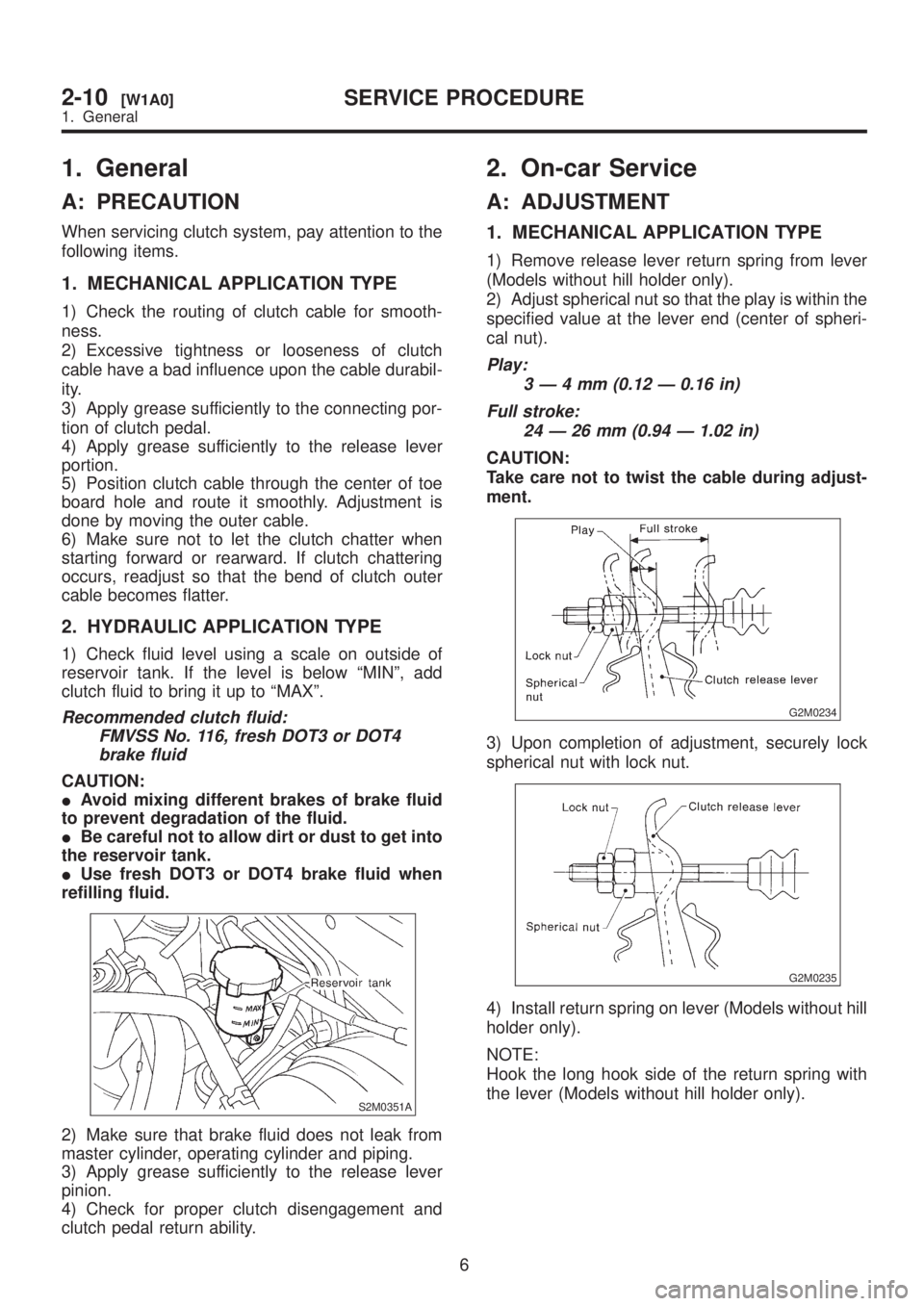
2) Adjust spherical nut so that the play is within the
specified value at the lever end (center of spheri-
cal nut).
Play:
3Ð4mm(0.12 Ð 0.16 in)
Full stroke:
24 Ð 26 mm (0.94 Ð 1.02 in)
CAUTION:
Take care not to twist the cable during adjust-
ment.
G2M0234
3) Upon completion of adjustment, securely lock
spherical nut with lock nut.
G2M0235
4) Install return spring on lever (Models without hill
holder only).
NOTE:
Hook the long hook side of the return spring with
the lever (Models without hill holder only).
6
2-10[W1A0]SERVICE PROCEDURE
1. General
Page 416 of 1456
1. General
A: PRECAUTION
When servicing clutch system, pay attention to the
following items.
1. MECHANICAL APPLICATION TYPE
1) Check the routing of clutch cable for smooth-
ness.
2) Excessive tightness or looseness of clutch
cable have a bad influence upon the cable durabil-
ity.
3) Apply grease sufficiently to the connecting por-
tion of clutch pedal.
4) Apply grease sufficiently to the release lever
portion.
5) Position clutch cable through the center of toe
board hole and route it smoothly. Adjustment is
done by moving the outer cable.
6) Make sure not to let the clutch chatter when
starting forward or rearward. If clutch chattering
occurs, readjust so that the bend of clutch outer
cable becomes flatter.
2. HYDRAULIC APPLICATION TYPE
1) Check fluid level using a scale on outside of
reservoir tank. If the level is below ªMINº, add
clutch fluid to bring it up to ªMAXº.
Recommended clutch fluid:
FMVSS No. 116, fresh DOT3 or DOT4
brake fluid
CAUTION:
IAvoid mixing different brakes of brake fluid
to prevent degradation of the fluid.
IBe careful not to allow dirt or dust to get into
the reservoir tank.
IUse fresh DOT3 or DOT4 brake fluid when
refilling fluid.
S2M0351A
2) Make sure that brake fluid does not leak from
master cylinder, operating cylinder and piping.
3) Apply grease sufficiently to the release lever
pinion.
4) Check for proper clutch disengagement and
clutch pedal return ability.
2. On-car Service
A: ADJUSTMENT
1. MECHANICAL APPLICATION TYPE
1) Remove release lever return spring from lever
(Models without hill holder only).
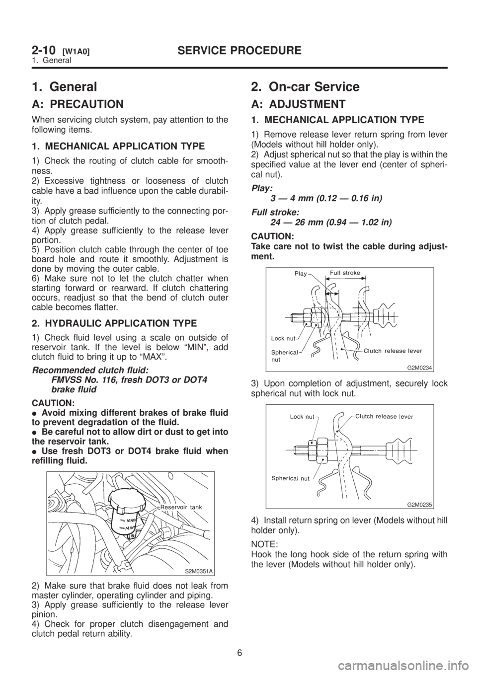
2) Adjust spherical nut so that the play is within the
specified value at the lever end (center of spheri-
cal nut).
Play:
3Ð4mm(0.12 Ð 0.16 in)
Full stroke:
24 Ð 26 mm (0.94 Ð 1.02 in)
CAUTION:
Take care not to twist the cable during adjust-
ment.
G2M0234
3) Upon completion of adjustment, securely lock
spherical nut with lock nut.
G2M0235
4) Install return spring on lever (Models without hill
holder only).
NOTE:
Hook the long hook side of the return spring with
the lever (Models without hill holder only).
6
2-10[W1A0]SERVICE PROCEDURE
1. General
Page 465 of 1456

1. Manual Transmission and Differential
ItemModel
AWD
2200 cc 2500 cc 2500 cc OUTBACK
Type 5-forward speeds with synchromesh and 1-reverse
Transmission gear ratio1st 3.545
2nd 2.111
3rd 1.448
4th 1.088
5th 0.780 0.871
Reverse 3.333
Front reduction
gearFinalType of gear Hypoid
Gear ratio 3.900 4.111
Rear reduction
gearTransferType of gear Helical
Gear ratio 1.000
FinalType of gear Hypoid
Gear ratio 3.900 4.111
Front differential Type and number of gear Straight bevel gear (Bevel pinion: 2, Bevel gear: 2)
Center differential Type and number of gearStraight bevel gear (Bevel pinion: 2, Bevel gear: 2 and vis-
cous coupling)
Transmission gear oilGL-5
Transmission oil capacity 3.5(3.7 US qt, 3.1 Imp qt)
2. Transmission Gear Oil
Recommended oil
B1H0024
3. Transmission Case
Assembly
Drive pinion shim adjustment
Drive pinion shim
Part No.Thickness
mm (in)Part No.Thickness
mm (in)
32295AA0310.150
(0.0059)32295AA0710.250
(0.0098)
32295AA0410.175
(0.0069)32295AA0810.275
(0.0108)
32295AA0510.200
(0.0079)32295AA0910.300
(0.0118)
32295AA0610.225
(0.0089)32295AA1010.500
(0.0197)
Hypoid gear backlash
0.13 Ð 0.18 mm (0.0051 Ð 0.0071 in)
Selection of main shaft rear plate
Main shaft rear plate
Dimension ªAº mm
(in)Part No. Mark
4.00 Ð 4.13
(0.1575 Ð 0.1626)32294AA041 1
3.87 Ð 3.99
(0.1524 Ð 0.1571)32294AA051 2
2
3-1[S100]SPECIFICATIONS AND SERVICE DATA
1. Manual Transmission and Differential
Page 466 of 1456
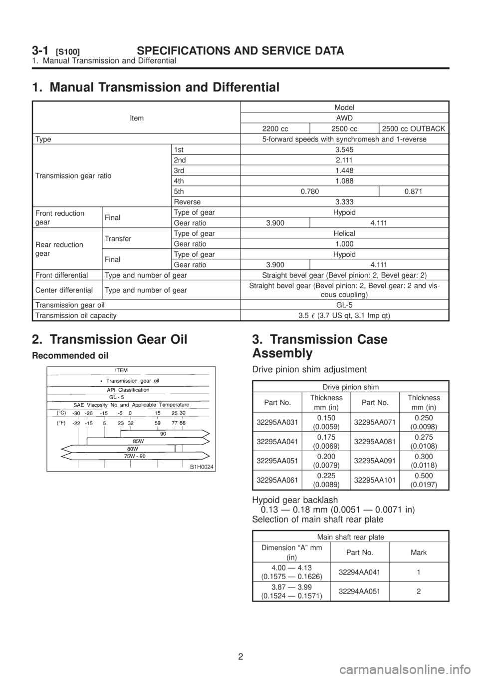
1. Manual Transmission and Differential
ItemModel
AWD
2200 cc 2500 cc 2500 cc OUTBACK
Type 5-forward speeds with synchromesh and 1-reverse
Transmission gear ratio1st 3.545
2nd 2.111
3rd 1.448
4th 1.088
5th 0.780 0.871
Reverse 3.333
Front reduction
gearFinalType of gear Hypoid
Gear ratio 3.900 4.111
Rear reduction
gearTransferType of gear Helical
Gear ratio 1.000
FinalType of gear Hypoid
Gear ratio 3.900 4.111
Front differential Type and number of gear Straight bevel gear (Bevel pinion: 2, Bevel gear: 2)
Center differential Type and number of gearStraight bevel gear (Bevel pinion: 2, Bevel gear: 2 and vis-
cous coupling)
Transmission gear oilGL-5
Transmission oil capacity 3.5(3.7 US qt, 3.1 Imp qt)
2. Transmission Gear Oil
Recommended oil
B1H0024
3. Transmission Case
Assembly
Drive pinion shim adjustment
Drive pinion shim
Part No.Thickness
mm (in)Part No.Thickness
mm (in)
32295AA0310.150
(0.0059)32295AA0710.250
(0.0098)
32295AA0410.175
(0.0069)32295AA0810.275
(0.0108)
32295AA0510.200
(0.0079)32295AA0910.300
(0.0118)
32295AA0610.225
(0.0089)32295AA1010.500
(0.0197)
Hypoid gear backlash
0.13 Ð 0.18 mm (0.0051 Ð 0.0071 in)
Selection of main shaft rear plate
Main shaft rear plate
Dimension ªAº mm
(in)Part No. Mark
4.00 Ð 4.13
(0.1575 Ð 0.1626)32294AA041 1
3.87 Ð 3.99
(0.1524 Ð 0.1571)32294AA051 2
2
3-1[S100]SPECIFICATIONS AND SERVICE DATA
1. Manual Transmission and Differential
Page 467 of 1456

1. Manual Transmission and Differential
ItemModel
AWD
2200 cc 2500 cc 2500 cc OUTBACK
Type 5-forward speeds with synchromesh and 1-reverse
Transmission gear ratio1st 3.545
2nd 2.111
3rd 1.448
4th 1.088
5th 0.780 0.871
Reverse 3.333
Front reduction
gearFinalType of gear Hypoid
Gear ratio 3.900 4.111
Rear reduction
gearTransferType of gear Helical
Gear ratio 1.000
FinalType of gear Hypoid
Gear ratio 3.900 4.111
Front differential Type and number of gear Straight bevel gear (Bevel pinion: 2, Bevel gear: 2)
Center differential Type and number of gearStraight bevel gear (Bevel pinion: 2, Bevel gear: 2 and vis-
cous coupling)
Transmission gear oilGL-5
Transmission oil capacity 3.5(3.7 US qt, 3.1 Imp qt)
2. Transmission Gear Oil
Recommended oil
B1H0024
3. Transmission Case
Assembly
Drive pinion shim adjustment
Drive pinion shim
Part No.Thickness
mm (in)Part No.Thickness
mm (in)
32295AA0310.150
(0.0059)32295AA0710.250
(0.0098)
32295AA0410.175
(0.0069)32295AA0810.275
(0.0108)
32295AA0510.200
(0.0079)32295AA0910.300
(0.0118)
32295AA0610.225
(0.0089)32295AA1010.500
(0.0197)
Hypoid gear backlash
0.13 Ð 0.18 mm (0.0051 Ð 0.0071 in)
Selection of main shaft rear plate
Main shaft rear plate
Dimension ªAº mm
(in)Part No. Mark
4.00 Ð 4.13
(0.1575 Ð 0.1626)32294AA041 1
3.87 Ð 3.99
(0.1524 Ð 0.1571)32294AA051 2
2
3-1[S100]SPECIFICATIONS AND SERVICE DATA
1. Manual Transmission and Differential