fuse diagram SUBARU LEGACY 1999 Service Repair Manual
[x] Cancel search | Manufacturer: SUBARU, Model Year: 1999, Model line: LEGACY, Model: SUBARU LEGACY 1999Pages: 1456, PDF Size: 59.93 MB
Page 1284 of 1456
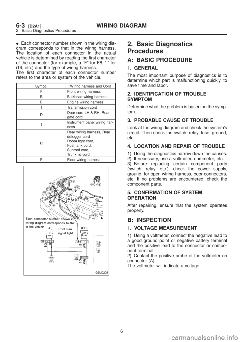
IEach connector number shown in the wiring dia-
gram corresponds to that in the wiring harness.
The location of each connector in the actual
vehicle is determined by reading the first character
of the connector (for example, a ªFº for F8, ªiº for
i16, etc.) and the type of wiring harness.
The first character of each connector number
refers to the area or system of the vehicle.
Symbol Wiring harness and Cord
F Front wiring harness
B Bulkhead wiring harness
E Engine wiring harness
T Transmission cord
DDoor cord LH & RH, Rear
gate cord
IInstrument panel wiring har-
ness
RRear wiring harness, Rear
defogger cord
Room light cord,
Fuel tank cord,
Sunroof cord,
Trunk lid cord
P Floor wiring harness
G6M0205
2. Basic Diagnostics
Procedures
A: BASIC PROCEDURE
1. GENERAL
The most important purpose of diagnostics is to
determine which part is malfunctioning quickly, to
save time and labor.
2. IDENTIFICATION OF TROUBLE
SYMPTOM
Determine what the problem is based on the symp-
tom.
3. PROBABLE CAUSE OF TROUBLE
Look at the wiring diagram and check the system's
circuit. Then check the switch, relay, fuse, ground,
etc.
4. LOCATION AND REPAIR OF TROUBLE
1) Using the diagnostics narrow down the causes.
2) If necessary, use a voltmeter, ohmmeter, etc.
3) Before replacing certain component parts
(switch, relay, etc.), check the power supply,
ground, for open wiring harness, poor connectors,
etc. If no problems are encountered, check the
component parts.
5. CONFIRMATION OF SYSTEM
OPERATION
After repairing, ensure that the system operates
properly.
B: INSPECTION
1. VOLTAGE MEASUREMENT
1) Using a voltmeter, connect the negative lead to
a good ground point or negative battery terminal
and the positive lead to the connector or compo-
nent terminal.
2) Contact the positive probe of the voltmeter on
connector (A).
The voltmeter will indicate a voltage.
6
6-3[D2A1]WIRING DIAGRAM
2. Basic Diagnostics Procedures
Page 1285 of 1456
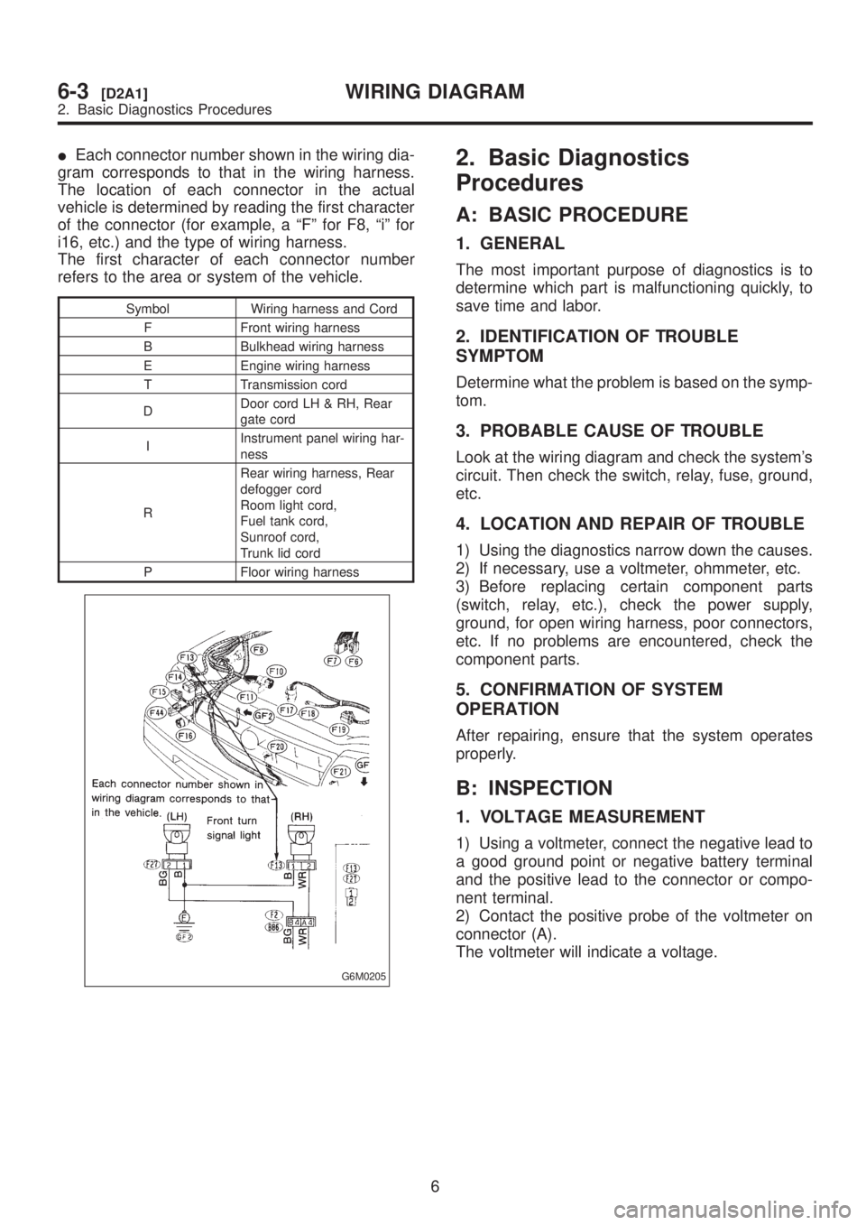
IEach connector number shown in the wiring dia-
gram corresponds to that in the wiring harness.
The location of each connector in the actual
vehicle is determined by reading the first character
of the connector (for example, a ªFº for F8, ªiº for
i16, etc.) and the type of wiring harness.
The first character of each connector number
refers to the area or system of the vehicle.
Symbol Wiring harness and Cord
F Front wiring harness
B Bulkhead wiring harness
E Engine wiring harness
T Transmission cord
DDoor cord LH & RH, Rear
gate cord
IInstrument panel wiring har-
ness
RRear wiring harness, Rear
defogger cord
Room light cord,
Fuel tank cord,
Sunroof cord,
Trunk lid cord
P Floor wiring harness
G6M0205
2. Basic Diagnostics
Procedures
A: BASIC PROCEDURE
1. GENERAL
The most important purpose of diagnostics is to
determine which part is malfunctioning quickly, to
save time and labor.
2. IDENTIFICATION OF TROUBLE
SYMPTOM
Determine what the problem is based on the symp-
tom.
3. PROBABLE CAUSE OF TROUBLE
Look at the wiring diagram and check the system's
circuit. Then check the switch, relay, fuse, ground,
etc.
4. LOCATION AND REPAIR OF TROUBLE
1) Using the diagnostics narrow down the causes.
2) If necessary, use a voltmeter, ohmmeter, etc.
3) Before replacing certain component parts
(switch, relay, etc.), check the power supply,
ground, for open wiring harness, poor connectors,
etc. If no problems are encountered, check the
component parts.
5. CONFIRMATION OF SYSTEM
OPERATION
After repairing, ensure that the system operates
properly.
B: INSPECTION
1. VOLTAGE MEASUREMENT
1) Using a voltmeter, connect the negative lead to
a good ground point or negative battery terminal
and the positive lead to the connector or compo-
nent terminal.
2) Contact the positive probe of the voltmeter on
connector (A).
The voltmeter will indicate a voltage.
6
6-3[D2A1]WIRING DIAGRAM
2. Basic Diagnostics Procedures
Page 1287 of 1456
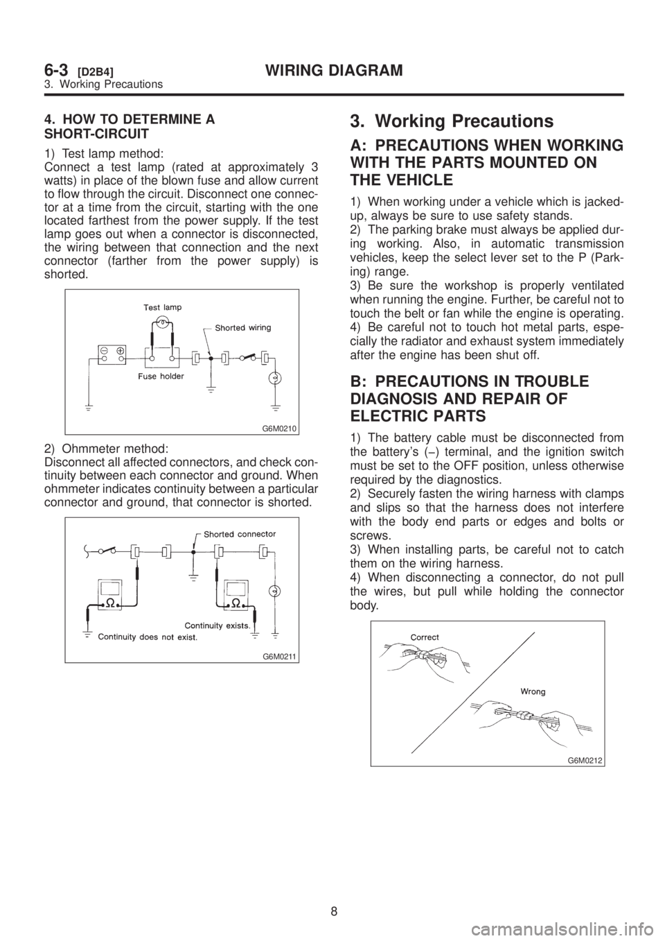
4. HOW TO DETERMINE A
SHORT-CIRCUIT
1) Test lamp method:
Connect a test lamp (rated at approximately 3
watts) in place of the blown fuse and allow current
to flow through the circuit. Disconnect one connec-
tor at a time from the circuit, starting with the one
located farthest from the power supply. If the test
lamp goes out when a connector is disconnected,
the wiring between that connection and the next
connector (farther from the power supply) is
shorted.
G6M0210
2) Ohmmeter method:
Disconnect all affected connectors, and check con-
tinuity between each connector and ground. When
ohmmeter indicates continuity between a particular
connector and ground, that connector is shorted.
G6M0211
3. Working Precautions
A: PRECAUTIONS WHEN WORKING
WITH THE PARTS MOUNTED ON
THE VEHICLE
1) When working under a vehicle which is jacked-
up, always be sure to use safety stands.
2) The parking brake must always be applied dur-
ing working. Also, in automatic transmission
vehicles, keep the select lever set to the P (Park-
ing) range.
3) Be sure the workshop is properly ventilated
when running the engine. Further, be careful not to
touch the belt or fan while the engine is operating.
4) Be careful not to touch hot metal parts, espe-
cially the radiator and exhaust system immediately
after the engine has been shut off.
B: PRECAUTIONS IN TROUBLE
DIAGNOSIS AND REPAIR OF
ELECTRIC PARTS
1) The battery cable must be disconnected from
the battery's (þ) terminal, and the ignition switch
must be set to the OFF position, unless otherwise
required by the diagnostics.
2) Securely fasten the wiring harness with clamps
and slips so that the harness does not interfere
with the body end parts or edges and bolts or
screws.
3) When installing parts, be careful not to catch
them on the wiring harness.
4) When disconnecting a connector, do not pull
the wires, but pull while holding the connector
body.
G6M0212
8
6-3[D2B4]WIRING DIAGRAM
3. Working Precautions
Page 1288 of 1456
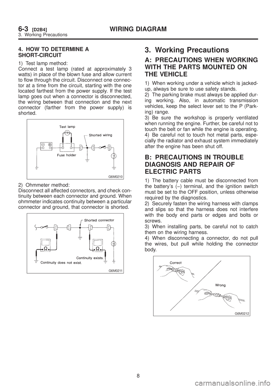
4. HOW TO DETERMINE A
SHORT-CIRCUIT
1) Test lamp method:
Connect a test lamp (rated at approximately 3
watts) in place of the blown fuse and allow current
to flow through the circuit. Disconnect one connec-
tor at a time from the circuit, starting with the one
located farthest from the power supply. If the test
lamp goes out when a connector is disconnected,
the wiring between that connection and the next
connector (farther from the power supply) is
shorted.
G6M0210
2) Ohmmeter method:
Disconnect all affected connectors, and check con-
tinuity between each connector and ground. When
ohmmeter indicates continuity between a particular
connector and ground, that connector is shorted.
G6M0211
3. Working Precautions
A: PRECAUTIONS WHEN WORKING
WITH THE PARTS MOUNTED ON
THE VEHICLE
1) When working under a vehicle which is jacked-
up, always be sure to use safety stands.
2) The parking brake must always be applied dur-
ing working. Also, in automatic transmission
vehicles, keep the select lever set to the P (Park-
ing) range.
3) Be sure the workshop is properly ventilated
when running the engine. Further, be careful not to
touch the belt or fan while the engine is operating.
4) Be careful not to touch hot metal parts, espe-
cially the radiator and exhaust system immediately
after the engine has been shut off.
B: PRECAUTIONS IN TROUBLE
DIAGNOSIS AND REPAIR OF
ELECTRIC PARTS
1) The battery cable must be disconnected from
the battery's (þ) terminal, and the ignition switch
must be set to the OFF position, unless otherwise
required by the diagnostics.
2) Securely fasten the wiring harness with clamps
and slips so that the harness does not interfere
with the body end parts or edges and bolts or
screws.
3) When installing parts, be careful not to catch
them on the wiring harness.
4) When disconnecting a connector, do not pull
the wires, but pull while holding the connector
body.
G6M0212
8
6-3[D2B4]WIRING DIAGRAM
3. Working Precautions
Page 1290 of 1456
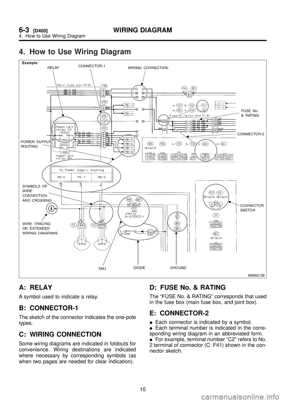
4. How to Use Wiring Diagram
B6M0213B
A: RELAY
A symbol used to indicate a relay.
B: CONNECTOR-1
The sketch of the connector indicates the one-pole
types.
C: WIRING CONNECTION
Some wiring diagrams are indicated in foldouts for
convenience. Wiring destinations are indicated
where necessary by corresponding symbols (as
when two pages are needed for clear indication).
D: FUSE No. & RATING
The ªFUSE No. & RATINGº corresponds that used
in the fuse box (main fuse box, and joint box).
E: CONNECTOR-2
IEach connector is indicated by a symbol.
IEach terminal number is indicated in the corre-
sponding wiring diagram in an abbreviated form.
IFor example, terminal number ªC2º refers to No.
2 terminal of connector (C: F41) shown in the con-
nector sketch.
10
6-3[D400]WIRING DIAGRAM
4. How to Use Wiring Diagram
Page 1291 of 1456
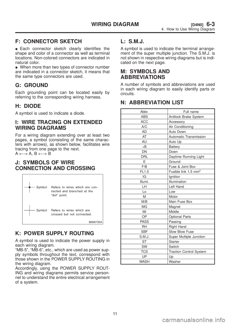
F: CONNECTOR SKETCH
IEach connector sketch clearly identifies the
shape and color of a connector as well as terminal
locations. Non-colored connectors are indicated in
natural color.
IWhen more than two types of connector number
are indicated in a connector sketch, it means that
the same type connectors are used.
G: GROUND
Each grounding point can be located easily by
referring to the corresponding wiring harness.
H: DIODE
A symbol is used to indicate a diode.
I: WIRE TRACING ON EXTENDED
WIRING DIAGRAMS
For a wiring diagram extending over at least two
pages, a symbol (consisting of the same charac-
ters with arrows), as shown below, facilitates wire
tracing from one page to the next.
A¨A, B¨B
J: SYMBOLS OF WIRE
CONNECTION AND CROSSING
B6M0750A
K: POWER SUPPLY ROUTING
A symbol is used to indicate the power supply in
each wiring diagram.
ªMB-5º, ªMB-6º, etc., which are used as power sup-
ply symbols throughout the text, correspond with
those shown in the POWER SUPPLY ROUTING in
the wiring diagram.
Accordingly, using the POWER SUPPLY ROUT-
ING and wiring diagrams permits service person-
nel to understand the entire electrical arrangement
of a system.
L: S.M.J.
A symbol is used to indicate the terminal arrange-
ment of the super multiple junction. The S.M.J. is
not shown in respective wiring diagrams but is indi-
cated on the next page.
M: SYMBOLS AND
ABBREVIATIONS
A number of symbols and abbreviations are used
in each wiring diagram to easily identify parts or
circuits.
N: ABBREVIATION LIST
Abbr. Full name
ABS Antilock Brake System
ACC Accessory
A/C Air Conditioning
AD Auto Down
AT Automatic Transmission
AU Auto Up
+B Battery
DN Down
DRL Daytime Running Light
E Ground
F/B Fuse & Joint Box
FL1.5 Fusible link 1.5 mm
2
IG Ignition
Illumi. Illumination
LH Left Hand
Lo Low
M Motor
M/B Main Fuse Box
MG Magnet
Mi Middle
OP Optional Parts
PASS Passing
RH Right Hand
SBF Slow Blow Fuse
S.M.J. Super Multiple Junction
ST Starter
SW Switch
TCS Traction Control System
UP Up
WASH Washer
11
[D4N0]6-3WIRING DIAGRAM
4. How to Use Wiring Diagram
Page 1296 of 1456
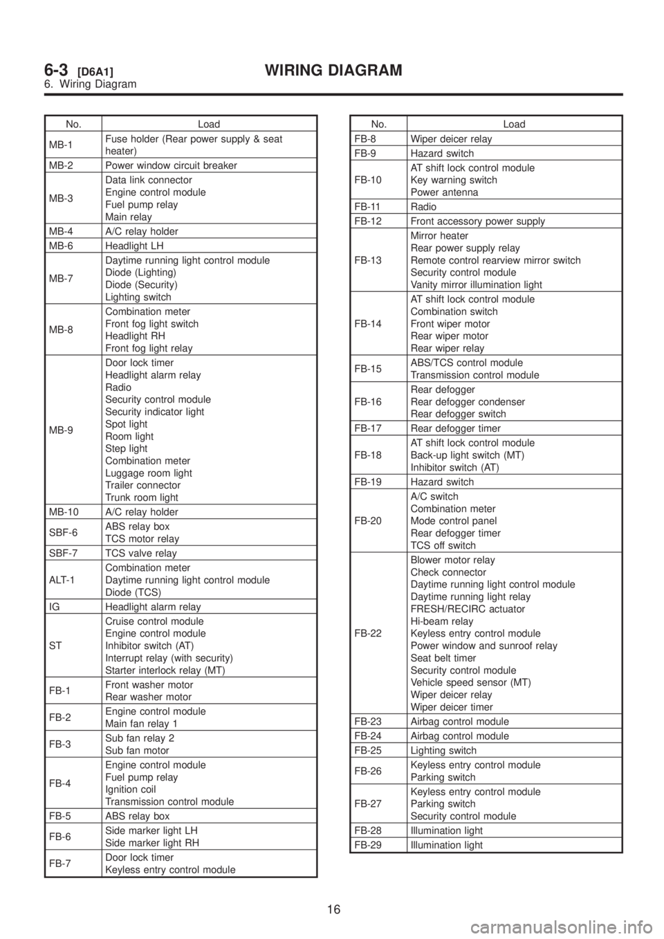
No. Load
MB-1Fuse holder (Rear power supply & seat
heater)
MB-2 Power window circuit breaker
MB-3Data link connector
Engine control module
Fuel pump relay
Main relay
MB-4 A/C relay holder
MB-6 Headlight LH
MB-7Daytime running light control module
Diode (Lighting)
Diode (Security)
Lighting switch
MB-8Combination meter
Front fog light switch
Headlight RH
Front fog light relay
MB-9Door lock timer
Headlight alarm relay
Radio
Security control module
Security indicator light
Spot light
Room light
Step light
Combination meter
Luggage room light
Trailer connector
Trunk room light
MB-10 A/C relay holder
SBF-6ABS relay box
TCS motor relay
SBF-7 TCS valve relay
ALT-1Combination meter
Daytime running light control module
Diode (TCS)
IG Headlight alarm relay
STCruise control module
Engine control module
Inhibitor switch (AT)
Interrupt relay (with security)
Starter interlock relay (MT)
FB-1Front washer motor
Rear washer motor
FB-2Engine control module
Main fan relay 1
FB-3Sub fan relay 2
Sub fan motor
FB-4Engine control module
Fuel pump relay
Ignition coil
Transmission control module
FB-5 ABS relay box
FB-6Side marker light LH
Side marker light RH
FB-7Door lock timer
Keyless entry control moduleNo. Load
FB-8 Wiper deicer relay
FB-9 Hazard switch
FB-10AT shift lock control module
Key warning switch
Power antenna
FB-11 Radio
FB-12 Front accessory power supply
FB-13Mirror heater
Rear power supply relay
Remote control rearview mirror switch
Security control module
Vanity mirror illumination light
FB-14AT shift lock control module
Combination switch
Front wiper motor
Rear wiper motor
Rear wiper relay
FB-15ABS/TCS control module
Transmission control module
FB-16Rear defogger
Rear defogger condenser
Rear defogger switch
FB-17 Rear defogger timer
FB-18AT shift lock control module
Back-up light switch (MT)
Inhibitor switch (AT)
FB-19 Hazard switch
FB-20A/C switch
Combination meter
Mode control panel
Rear defogger timer
TCS off switch
FB-22Blower motor relay
Check connector
Daytime running light control module
Daytime running light relay
FRESH/RECIRC actuator
Hi-beam relay
Keyless entry control module
Power window and sunroof relay
Seat belt timer
Security control module
Vehicle speed sensor (MT)
Wiper deicer relay
Wiper deicer timer
FB-23 Airbag control module
FB-24 Airbag control module
FB-25 Lighting switch
FB-26Keyless entry control module
Parking switch
FB-27Keyless entry control module
Parking switch
Security control module
FB-28 Illumination light
FB-29 Illumination light
16
6-3[D6A1]WIRING DIAGRAM
6. Wiring Diagram
Page 1413 of 1456
![SUBARU LEGACY 1999 Service Repair Manual 7. Electrical Unit Location
A: LIST
Electrical unit Index No.
ABS control module <Ref. to 4-4 [T300].>
ABS G sensor (MT) <Ref. to 4-4 [T300].>
A/C compressor relay <Ref. to 6-3 [D7B1].>
A/C fuse <Ref.](/img/17/57435/w960_57435-1412.png "SUBARU LEGACY 1999 Service Repair Manual 7. Electrical Unit Location
A: LIST
Electrical unit Index No.
ABS control module <Ref. to 4-4 [T300].>
ABS G sensor (MT) <Ref. to 4-4 [T300].>
A/C compressor relay <Ref. to 6-3 [D7B1].>
A/C fuse <Ref.")
7. Electrical Unit Location
A: LIST
Electrical unit Index No.
ABS control module
ABS G sensor (MT)
A/C compressor relay
A/C fuse
A/C main fan relay 1
A/C main fan relay 2
A/C pressure switch
A/C sub fan relay 2
ATF temperature sensor
Blower motor resistor
Blower relay
Camshaft position sensor
Check connector
Clutch switch (MT)
Crankshaft position sensor
Cruise control module
Cruise control pump
Data link connector (for
OBD-II G.S.T.)
Data link connector (for
S.S.M.)
Diagnosis connector
Diagnosis terminal (Ground)
Door lock timer
Engine control module
Engine coolant temperature
sensor
Engine hood switch (Secu-
rity)
Evaporator thermoswitch
F/B
FRESH/RECIRC actuator
Fuel pump relay
Fuel gauge module
Fuel gauge sub module
(AWD)
FWD switch (AT)
Headlight alarm relay
(Security)
Headlight relay LH
Electrical unit Index No.
Headlight relay RH
Horn relay
Hydraulic unit (ABS)
Ignition coil
Ignitor
Idle air control solenoid
valve
Illumination control module
Inhibitor switch
Knock sensor
Main fan relay
Main relay
Mass air flow sensor
Mode actuator
M/B
Oil pressure switch
Oxygen sensor
Pedal stroke sensor (TCS)
Power window and sunroof
relay
Power window circuit
breaker
Purge control solenoid valve
Rear defogger relay
Seat belt timer
Security control module
Shift lock control module
Starter interrupt relay (Secu-
rity)
Stop & brake switch (With
cruise control)
Sunroof control module
Tail and illumination relay
TCS control module
TCS motor relay
TCS valve relay
Throttle position sensor
Test mode connector
Transmission control mod-
ule
Turn & hazard module
Vehicle speed sensor 1
Vehicle speed sensor 2
133
[D7A0]6-3WIRING DIAGRAM
7. Electrical Unit Location
Page 1414 of 1456
![SUBARU LEGACY 1999 Service Repair Manual B: LOCATION
1. ENGINE ROOM
B2M0018F
(1) FWD switch (AT) <Ref. to 6-3
[D7B4].>
(2) A/C pressure switch <Ref. to 6-3
[D7B4].>
(3) Oil pressure switch <Ref. to 6-3
[D7B4].>
(4) M/B <Ref. to 6-3 [D7B4].>(](/img/17/57435/w960_57435-1413.png "SUBARU LEGACY 1999 Service Repair Manual B: LOCATION
1. ENGINE ROOM
B2M0018F
(1) FWD switch (AT) <Ref. to 6-3
[D7B4].>
(2) A/C pressure switch <Ref. to 6-3
[D7B4].>
(3) Oil pressure switch <Ref. to 6-3
[D7B4].>
(4) M/B <Ref. to 6-3 [D7B4].>(")
B: LOCATION
1. ENGINE ROOM
B2M0018F
(1) FWD switch (AT)
(2) A/C pressure switch
(3) Oil pressure switch
(4) M/B
(6) Headlight relay RH
(7) A/C compressor relay
(9) A/C sub fan relay 2
(10) A/C main fan relay 1
(11) A/C fuse
134
6-3[D7B1]WIRING DIAGRAM
7. Electrical Unit Location
Page 1422 of 1456
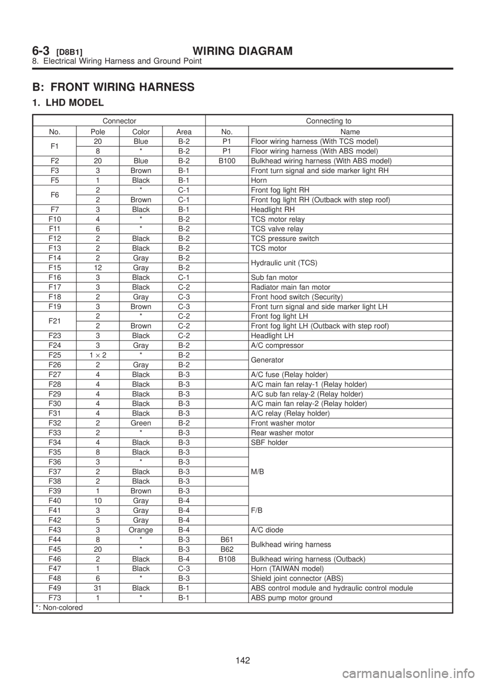
B: FRONT WIRING HARNESS
1. LHD MODEL
Connector Connecting to
No. Pole Color Area No. Name
F120 Blue B-2 P1 Floor wiring harness (With TCS model)
8 * B-2 P1 Floor wiring harness (With ABS model)
F2 20 Blue B-2 B100 Bulkhead wiring harness (With ABS model)
F3 3 Brown B-1 Front turn signal and side marker light RH
F5 1 Black B-1 Horn
F62 * C-1 Front fog light RH
2 Brown C-1 Front fog light RH (Outback with step roof)
F7 3 Black B-1 Headlight RH
F10 4 * B-2 TCS motor relay
F11 6 * B-2 TCS valve relay
F12 2 Black B-2 TCS pressure switch
F13 2 Black B-2 TCS motor
F14 2 Gray B-2
Hydraulic unit (TCS)
F15 12 Gray B-2
F16 3 Black C-1 Sub fan motor
F17 3 Black C-2 Radiator main fan motor
F18 2 Gray C-3 Front hood switch (Security)
F19 3 Brown C-3 Front turn signal and side marker light LH
F212 * C-2 Front fog light LH
2 Brown C-2 Front fog light LH (Outback with step roof)
F23 3 Black C-2 Headlight LH
F24 3 Gray B-2 A/C compressor
F25 1´2 * B-2
Generator
F26 2 Gray B-2
F27 4 Black B-3 A/C fuse (Relay holder)
F28 4 Black B-3 A/C main fan relay-1 (Relay holder)
F29 4 Black B-3 A/C sub fan relay-2 (Relay holder)
F30 4 Black B-3 A/C main fan relay-2 (Relay holder)
F31 4 Black B-3 A/C relay (Relay holder)
F32 2 Green B-2 Front washer motor
F33 2 * B-3 Rear washer motor
F34 4 Black B-3 SBF holder
F35 8 Black B-3
M/B F36 3 * B-3
F37 2 Black B-3
F38 2 Black B-3
F39 1 Brown B-3
F40 10 Gray B-4
F/B F41 3 Gray B-4
F42 5 Gray B-4
F43 3 Orange B-4 A/C diode
F44 8 * B-3 B61
Bulkhead wiring harness
F45 20 * B-3 B62
F46 2 Black B-4 B108 Bulkhead wiring harness (Outback)
F47 1 Black C-3 Horn (TAIWAN model)
F48 6 * B-3 Shield joint connector (ABS)
F49 31 Black B-1 ABS control module and hydraulic control module
F73 1 * B-1 ABS pump motor ground
*: Non-colored
142
6-3[D8B1]WIRING DIAGRAM
8. Electrical Wiring Harness and Ground Point