steering wheel adjustment SUBARU LEGACY 1999 Service Repair Manual
[x] Cancel search | Manufacturer: SUBARU, Model Year: 1999, Model line: LEGACY, Model: SUBARU LEGACY 1999Pages: 1456, PDF Size: 59.93 MB
Page 710 of 1456
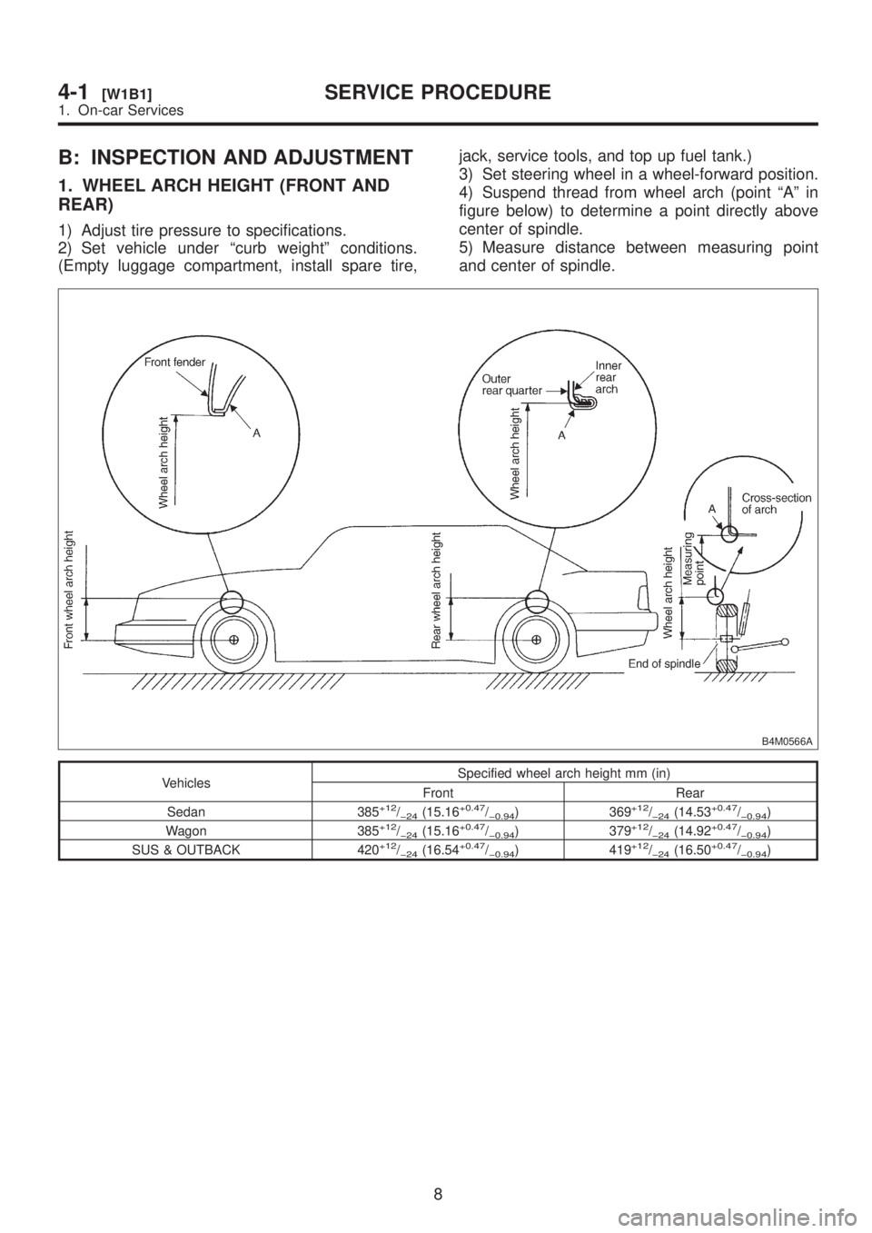
B: INSPECTION AND ADJUSTMENT
1. WHEEL ARCH HEIGHT (FRONT AND
REAR)
1) Adjust tire pressure to specifications.
2) Set vehicle under ªcurb weightº conditions.
(Empty luggage compartment, install spare tire,jack, service tools, and top up fuel tank.)
3) Set steering wheel in a wheel-forward position.
4) Suspend thread from wheel arch (point ªAº in
figure below) to determine a point directly above
center of spindle.
5) Measure distance between measuring point
and center of spindle.
B4M0566A
VehiclesSpecified wheel arch height mm (in)
Front Rear
Sedan 385
+12/þ24(15.16+0.47/þ0.94) 369+12/þ24(14.53+0.47/þ0.94)
Wagon 385+12/þ24(15.16+0.47/þ0.94) 379+12/þ24(14.92+0.47/þ0.94)
SUS & OUTBACK 420+12/þ24(16.54+0.47/þ0.94) 419+12/þ24(16.50+0.47/þ0.94)
8
4-1[W1B1]SERVICE PROCEDURE
1. On-car Services
Page 712 of 1456
3. CASTER (FRONT)
IInspection
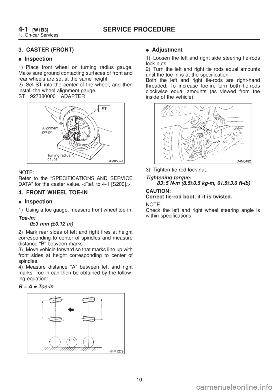
1) Place front wheel on turning radius gauge.
Make sure ground contacting surfaces of front and
rear wheels are set at the same height.
2) Set ST into the center of the wheel, and then
install the wheel alignment gauge.
ST 927380000 ADAPTER
B4M0567A
NOTE:
Refer to the ªSPECIFICATIONS AND SERVICE
DATAº for the caster value.
4. FRONT WHEEL TOE-IN
IInspection
1) Using a toe gauge, measure front wheel toe-in.
Toe-in:
0
±3mm(±0.12 in)
2) Mark rear sides of left and right tires at height
corresponding to center of spindles and measure
distance ªBº between marks.
3) Move vehicle forward so that marks line up with
front sides at height corresponding to center of
spindles.
4) Measure distance ªAº between left and right
marks. Toe-in can then be obtained by the follow-
ing equation:
B þ A = Toe-in
H4M1279
IAdjustment
1) Loosen the left and right side steering tie-rods
lock nuts.
2) Turn the left and right tie rods equal amounts
until the toe-in is at the specification.
Both the left and right tie-rods are right-hand
threaded. To increase toe-in, turn both tie-rods
clockwise equal amounts (as viewed from the
inside of the vehicle).
G4M0482
3) Tighten tie-rod lock nut.
Tightening torque:
83
±5 N´m (8.5±0.5 kg-m, 61.5±3.6 ft-lb)
CAUTION:
Correct tie-rod boot, if it is twisted.
NOTE:
Check the left and right wheel steering angle is
within specifications.
10
4-1[W1B3]SERVICE PROCEDURE
1. On-car Services
Page 715 of 1456
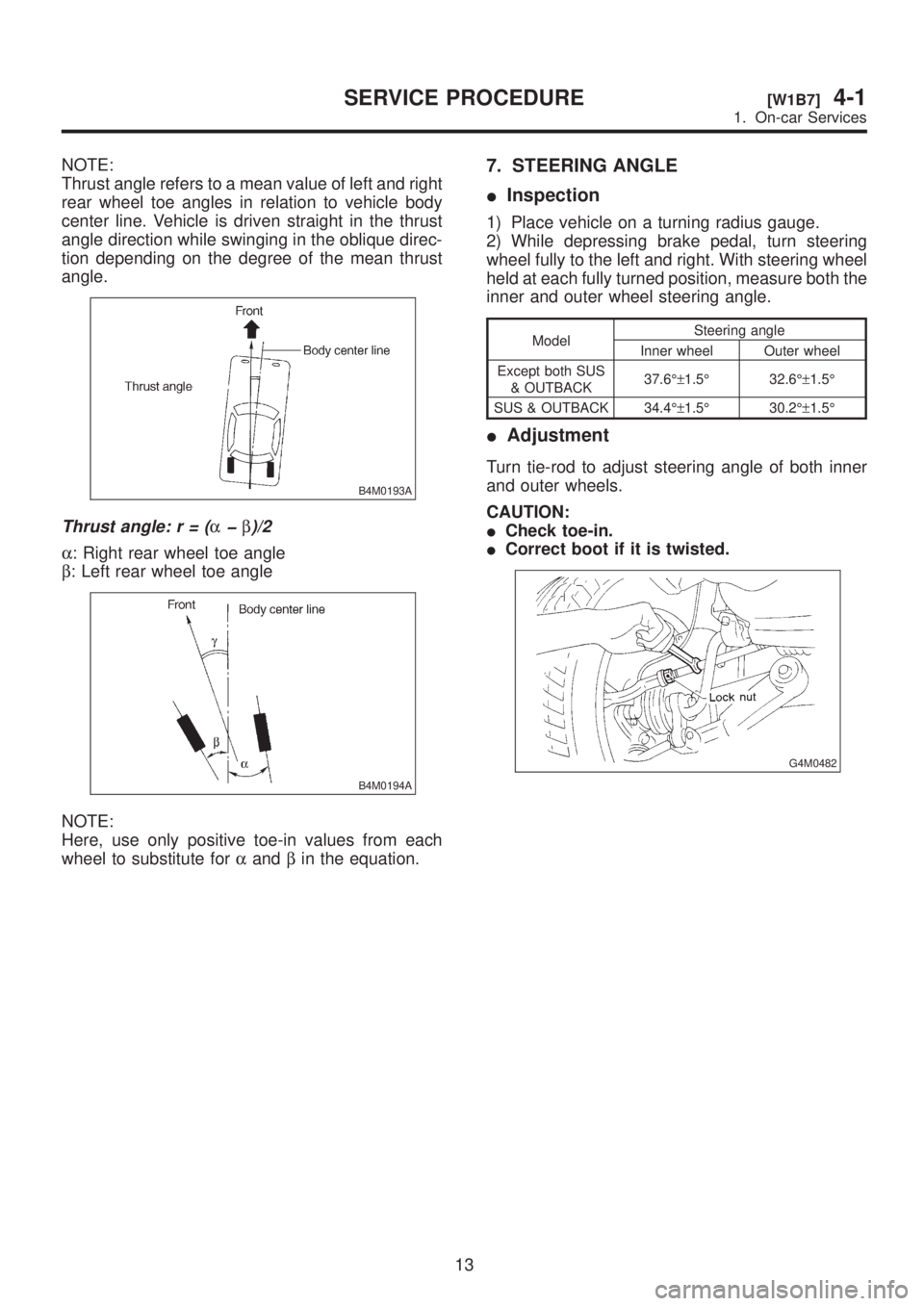
NOTE:
Thrust angle refers to a mean value of left and right
rear wheel toe angles in relation to vehicle body
center line. Vehicle is driven straight in the thrust
angle direction while swinging in the oblique direc-
tion depending on the degree of the mean thrust
angle.
B4M0193A
Thrust angle:r=(aþb)/2
a: Right rear wheel toe angle
b: Left rear wheel toe angle
B4M0194A
NOTE:
Here, use only positive toe-in values from each
wheel to substitute foraandbin the equation.
7. STEERING ANGLE
IInspection
1) Place vehicle on a turning radius gauge.
2) While depressing brake pedal, turn steering
wheel fully to the left and right. With steering wheel
held at each fully turned position, measure both the
inner and outer wheel steering angle.
ModelSteering angle
Inner wheel Outer wheel
Except both SUS
& OUTBACK37.6ɱ1.5É 32.6ɱ1.5É
SUS & OUTBACK 34.4ɱ1.5É 30.2ɱ1.5É
IAdjustment
Turn tie-rod to adjust steering angle of both inner
and outer wheels.
CAUTION:
ICheck toe-in.
ICorrect boot if it is twisted.
G4M0482
13
[W1B7]4-1SERVICE PROCEDURE
1. On-car Services
Page 813 of 1456
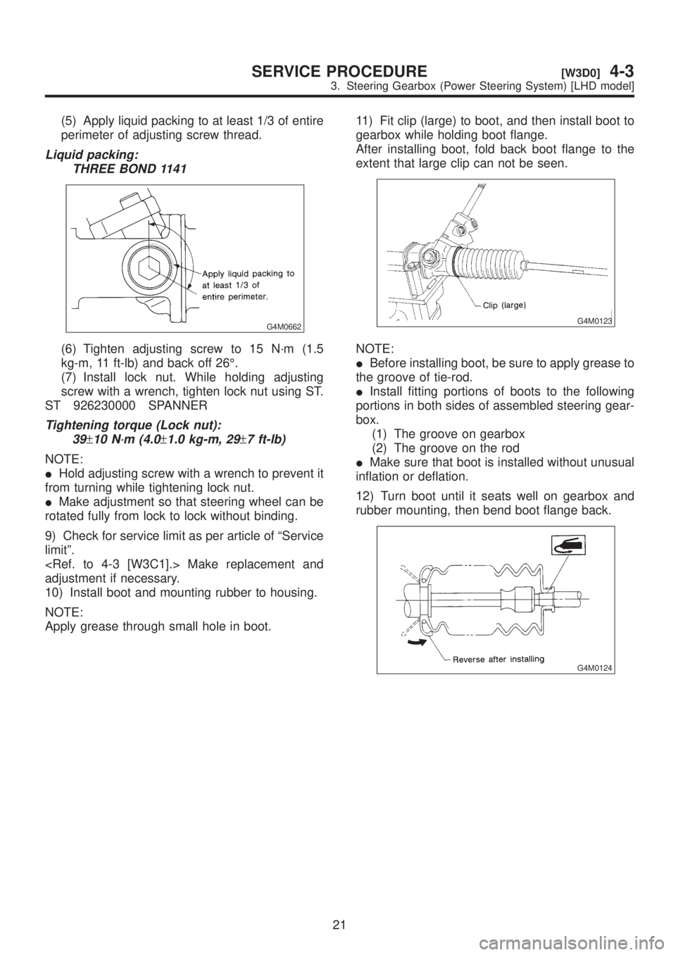
(5) Apply liquid packing to at least 1/3 of entire
perimeter of adjusting screw thread.
Liquid packing:
THREE BOND 1141
G4M0662
(6) Tighten adjusting screw to 15 N´m (1.5
kg-m, 11 ft-lb) and back off 26É.
(7) Install lock nut. While holding adjusting
screw with a wrench, tighten lock nut using ST.
ST 926230000 SPANNER
Tightening torque (Lock nut):
39
±10 N´m (4.0±1.0 kg-m, 29±7 ft-lb)
NOTE:
IHold adjusting screw with a wrench to prevent it
from turning while tightening lock nut.
IMake adjustment so that steering wheel can be
rotated fully from lock to lock without binding.
9) Check for service limit as per article of ªService
limitº.
adjustment if necessary.
10) Install boot and mounting rubber to housing.
NOTE:
Apply grease through small hole in boot.11) Fit clip (large) to boot, and then install boot to
gearbox while holding boot flange.
After installing boot, fold back boot flange to the
extent that large clip can not be seen.
G4M0123
NOTE:
IBefore installing boot, be sure to apply grease to
the groove of tie-rod.
IInstall fitting portions of boots to the following
portions in both sides of assembled steering gear-
box.
(1) The groove on gearbox
(2) The groove on the rod
IMake sure that boot is installed without unusual
inflation or deflation.
12) Turn boot until it seats well on gearbox and
rubber mounting, then bend boot flange back.
G4M0124
21
[W3D0]4-3SERVICE PROCEDURE
3. Steering Gearbox (Power Steering System) [LHD model]
Page 816 of 1456
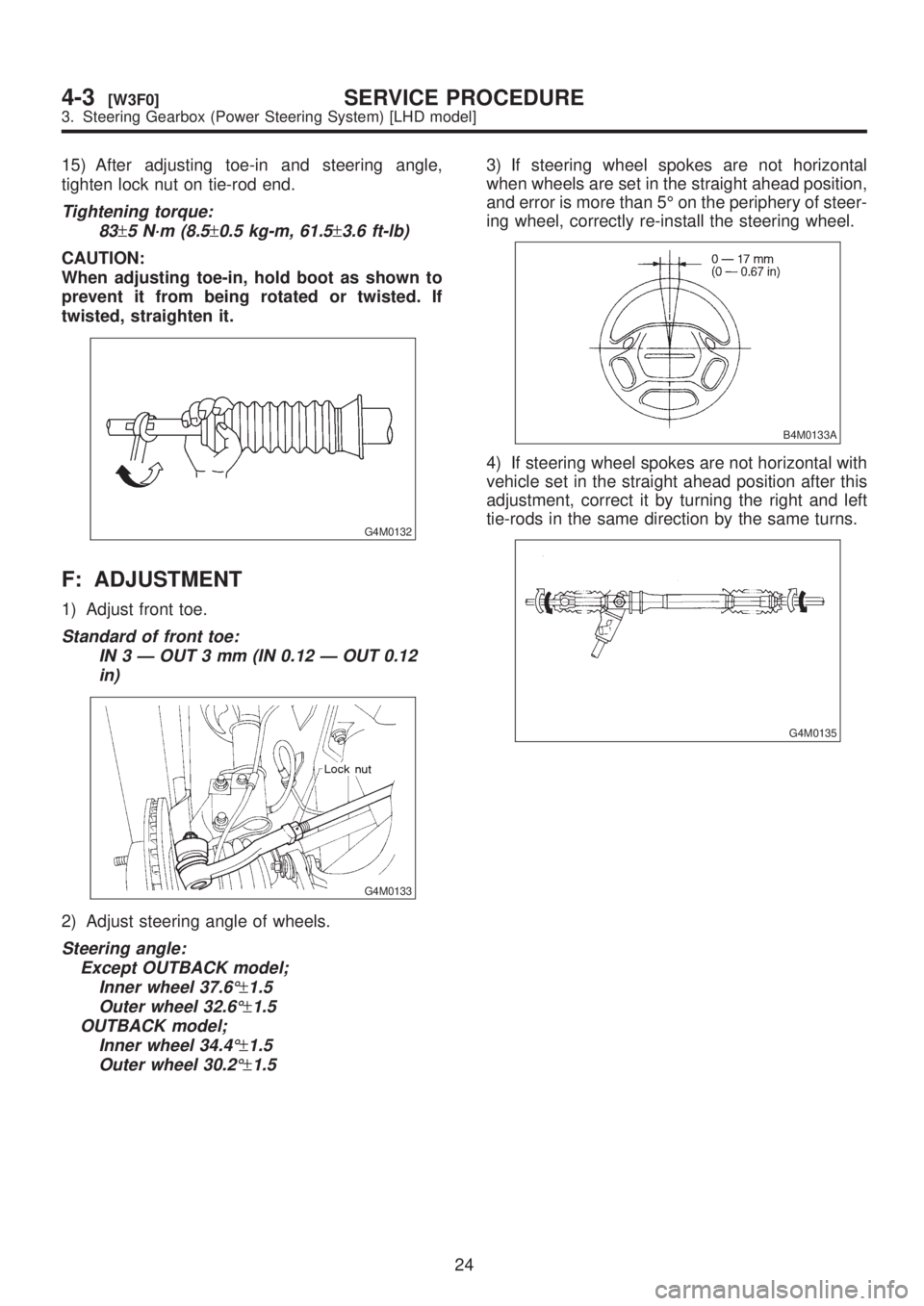
15) After adjusting toe-in and steering angle,
tighten lock nut on tie-rod end.
Tightening torque:
83
±5 N´m (8.5±0.5 kg-m, 61.5±3.6 ft-lb)
CAUTION:
When adjusting toe-in, hold boot as shown to
prevent it from being rotated or twisted. If
twisted, straighten it.
G4M0132
F: ADJUSTMENT
1) Adjust front toe.
Standard of front toe:
IN 3 Ð OUT 3 mm (IN 0.12 Ð OUT 0.12
in)
G4M0133
2) Adjust steering angle of wheels.
Steering angle:
Except OUTBACK model;
Inner wheel 37.6É
±1.5
Outer wheel 32.6É
±1.5
OUTBACK model;
Inner wheel 34.4É
±1.5
Outer wheel 30.2É
±1.5
3) If steering wheel spokes are not horizontal
when wheels are set in the straight ahead position,
and error is more than 5É on the periphery of steer-
ing wheel, correctly re-install the steering wheel.
B4M0133A
4) If steering wheel spokes are not horizontal with
vehicle set in the straight ahead position after this
adjustment, correct it by turning the right and left
tie-rods in the same direction by the same turns.
G4M0135
24
4-3[W3F0]SERVICE PROCEDURE
3. Steering Gearbox (Power Steering System) [LHD model]
Page 826 of 1456
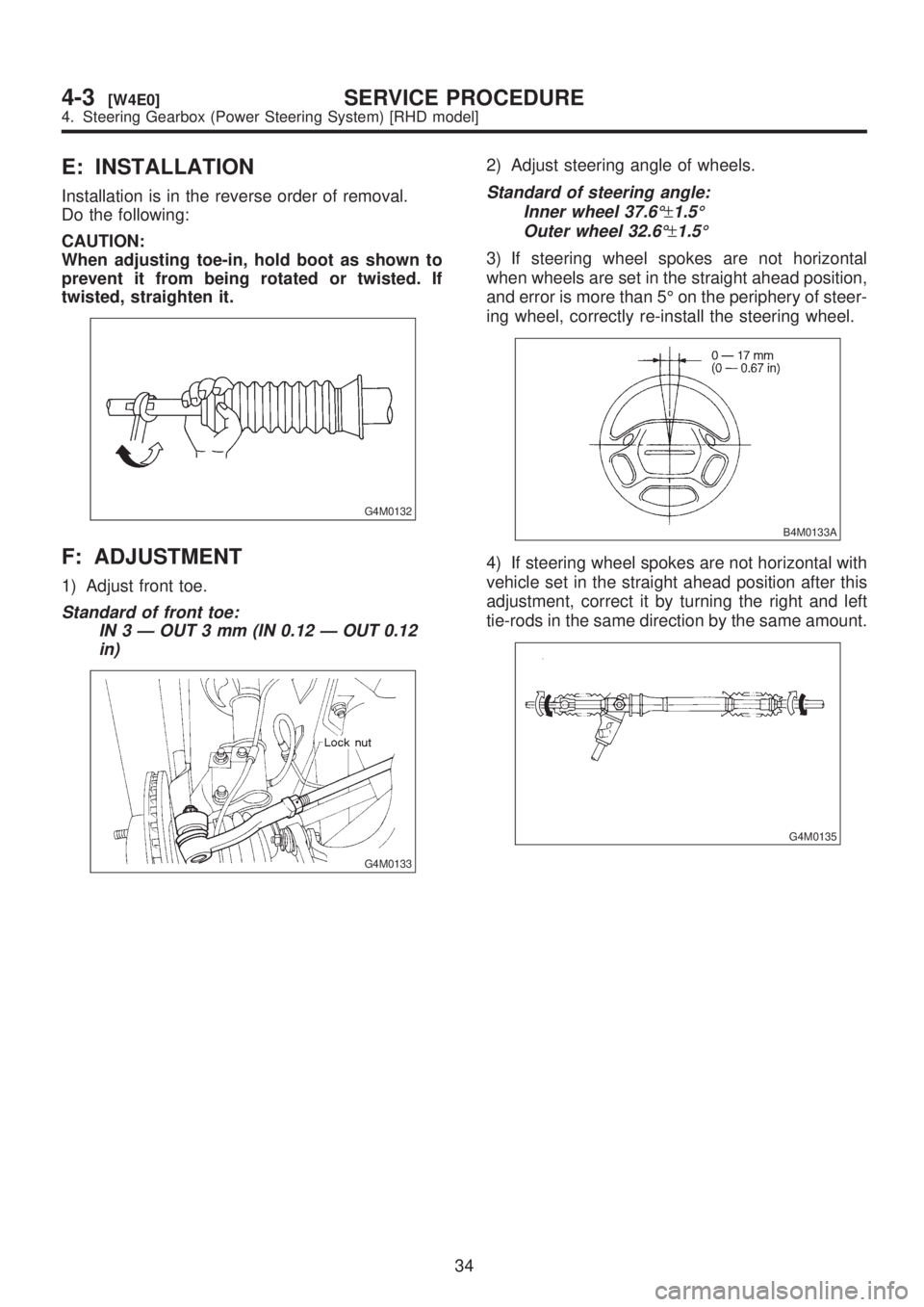
E: INSTALLATION
Installation is in the reverse order of removal.
Do the following:
CAUTION:
When adjusting toe-in, hold boot as shown to
prevent it from being rotated or twisted. If
twisted, straighten it.
G4M0132
F: ADJUSTMENT
1) Adjust front toe.
Standard of front toe:
IN 3 Ð OUT 3 mm (IN 0.12 Ð OUT 0.12
in)
G4M0133
2) Adjust steering angle of wheels.
Standard of steering angle:
Inner wheel 37.6É
±1.5É
Outer wheel 32.6É
±1.5É
3) If steering wheel spokes are not horizontal
when wheels are set in the straight ahead position,
and error is more than 5É on the periphery of steer-
ing wheel, correctly re-install the steering wheel.
B4M0133A
4) If steering wheel spokes are not horizontal with
vehicle set in the straight ahead position after this
adjustment, correct it by turning the right and left
tie-rods in the same direction by the same amount.
G4M0135
34
4-3[W4E0]SERVICE PROCEDURE
4. Steering Gearbox (Power Steering System) [RHD model]
Page 828 of 1456
6) Leakage from ªeº
The cylinder seal is damaged. Replace rack bush
with a new one.
7) Leakage from ªfº
There are two possible causes. Take following step
first. Remove the pipe assembly B from the valve
housing, and close the circuit with ST.
ST 926420000 PLUG
Turn the steering wheel from lock to lock 30 to 40
times with the engine running, then make compari-
son of the leaked portion between immediately
after and several hours after this operation.
CAUTION:
IIf leakage from ªfº is noted again:
The oil seal of pinion and valve assembly is
damaged. Replace pinion and valve assembly
with a new one. Or replace the oil seal and the
parts that are damaged during disassembly
with new ones.
IIf oil stops leaking from ªfº:
The oil seal of rack housing is damaged.
Replace the oil seal and the parts that are dam-
aged during disassembly with new ones.
B: DISASSEMBLY
NOTE:
This section focuses on the disassembly and reas-
sembly of control valve. For the inspection and
adjustment and the service procedures for associ-
ated parts, refer to ªSteering Gearbox (Power
Steering System) [LHD model]º.
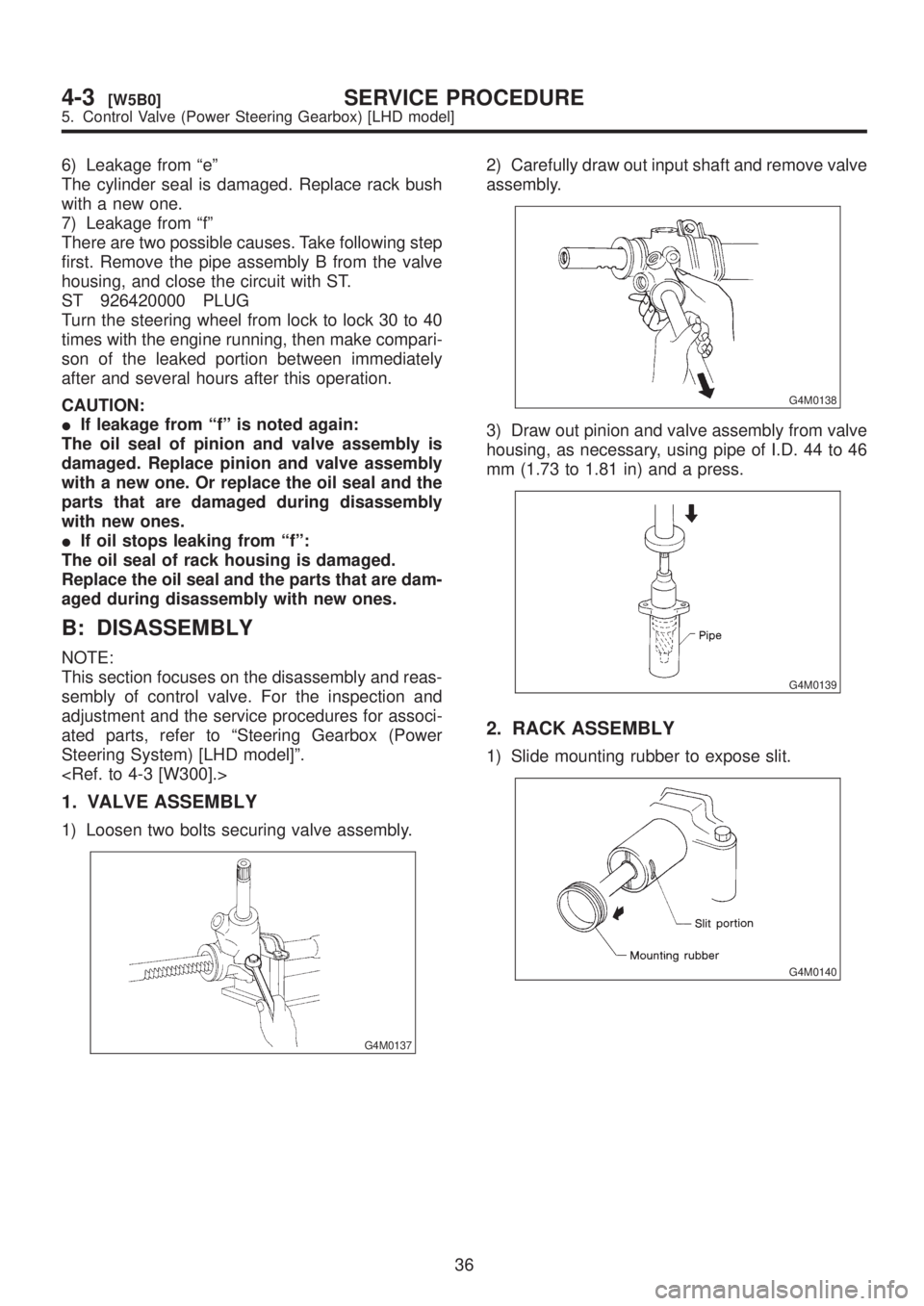
1. VALVE ASSEMBLY
1) Loosen two bolts securing valve assembly.
G4M0137
2) Carefully draw out input shaft and remove valve
assembly.
G4M0138
3) Draw out pinion and valve assembly from valve
housing, as necessary, using pipe of I.D. 44 to 46
mm (1.73 to 1.81 in) and a press.
G4M0139
2. RACK ASSEMBLY
1) Slide mounting rubber to expose slit.
G4M0140
36
4-3[W5B0]SERVICE PROCEDURE
5. Control Valve (Power Steering Gearbox) [LHD model]
Page 835 of 1456
boots toward tie-rod end side, respectively, with the
gearbox mounted to the vehicle, and remove oil
from the surrounding portions. Then, turn the steer-
ing wheel from lock to lock 30 to 40 times with the
engine running, then make comparison of the
leaked portion immediately after and several hours
after this operation.
6) Leakage from ªeº
There are two possible causes. Take following step
first. Remove the pipe assembly B from the valve
housing, and close the circuit with ST.
ST 926420000 PLUG
Turn the steering wheel from lock to lock 30 to 40
times with the engine running, then make compari-
son of the leaked portion between immediately
after and several hours after this operation.
CAUTION:
IIf leakage from ªeº is noted again:
The oil seal of pinion and valve assembly is
damaged. Replace pinion and valve assembly
with a new one. Or replace the oil seal and the
parts that are damaged during disassembly
with new ones.
IIf oil stops leaking from ªeº:
The oil seal of rack housing is damaged.
Replace the oil seal and the parts that are dam-
aged during disassembly with new ones.
B: DISASSEMBLY
NOTE:
This section focuses on the disassembly and reas-
sembly of control valve. For the inspection and
adjustment and the service procedures for associ-
ated parts, refer to ªSteering Gearbox (Power
Steering System) [RHD model]º.
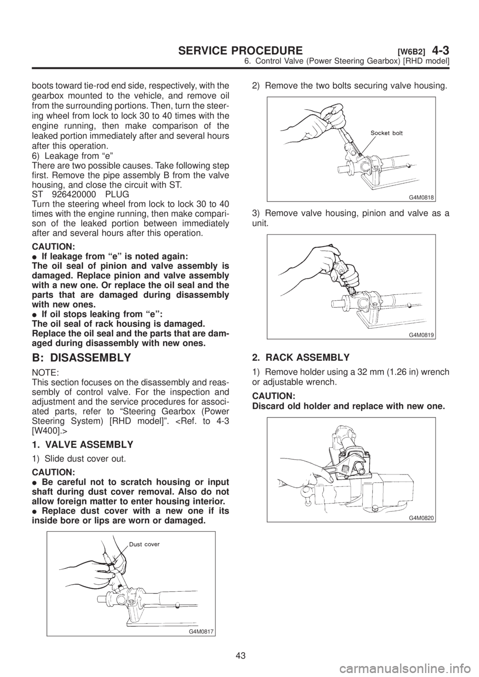
1. VALVE ASSEMBLY
1) Slide dust cover out.
CAUTION:
IBe careful not to scratch housing or input
shaft during dust cover removal. Also do not
allow foreign matter to enter housing interior.
IReplace dust cover with a new one if its
inside bore or lips are worn or damaged.
G4M0817
2) Remove the two bolts securing valve housing.
G4M0818
3) Remove valve housing, pinion and valve as a
unit.
G4M0819
2. RACK ASSEMBLY
1) Remove holder using a 32 mm (1.26 in) wrench
or adjustable wrench.
CAUTION:
Discard old holder and replace with new one.
G4M0820
43
[W6B2]4-3SERVICE PROCEDURE
6. Control Valve (Power Steering Gearbox) [RHD model]
Page 839 of 1456
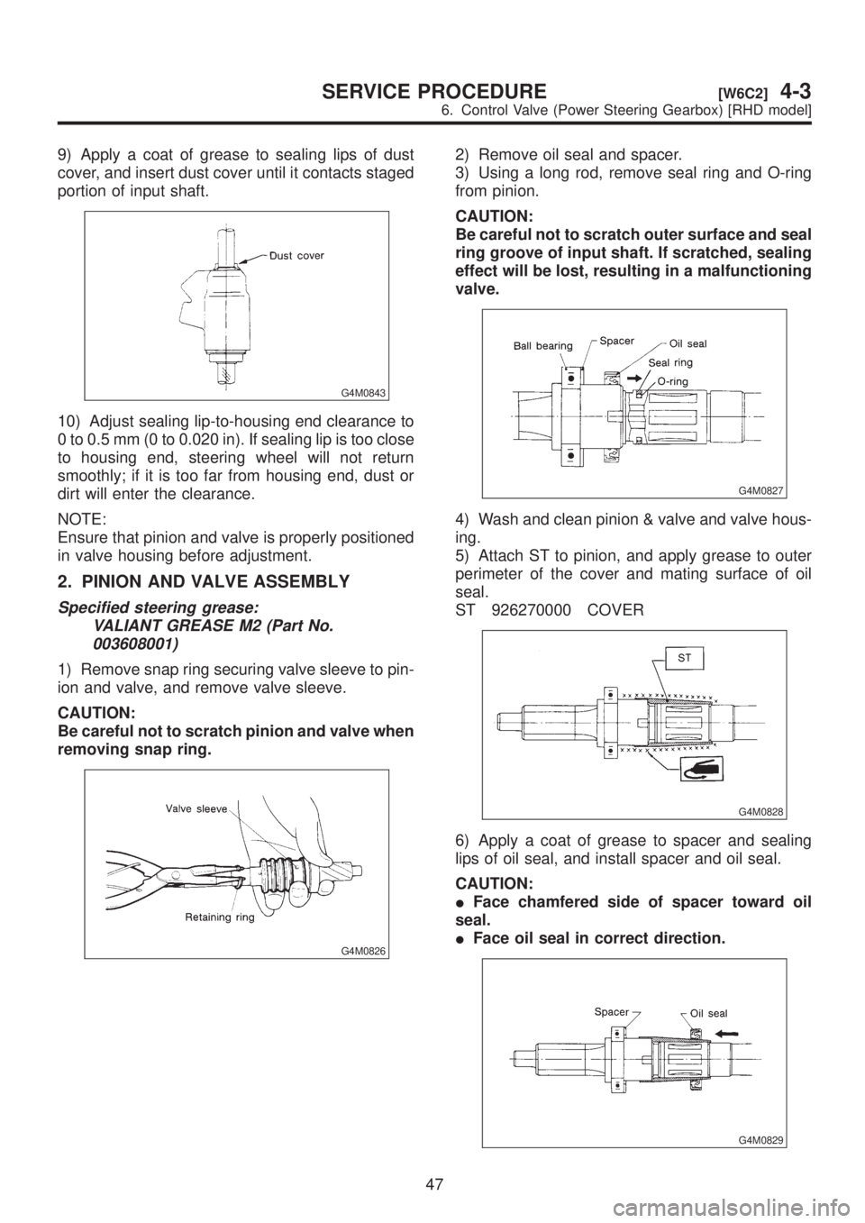
9) Apply a coat of grease to sealing lips of dust
cover, and insert dust cover until it contacts staged
portion of input shaft.
G4M0843
10) Adjust sealing lip-to-housing end clearance to
0 to 0.5 mm (0 to 0.020 in). If sealing lip is too close
to housing end, steering wheel will not return
smoothly; if it is too far from housing end, dust or
dirt will enter the clearance.
NOTE:
Ensure that pinion and valve is properly positioned
in valve housing before adjustment.
2. PINION AND VALVE ASSEMBLY
Specified steering grease:
VALIANT GREASE M2 (Part No.
003608001)
1) Remove snap ring securing valve sleeve to pin-
ion and valve, and remove valve sleeve.
CAUTION:
Be careful not to scratch pinion and valve when
removing snap ring.
G4M0826
2) Remove oil seal and spacer.
3) Using a long rod, remove seal ring and O-ring
from pinion.
CAUTION:
Be careful not to scratch outer surface and seal
ring groove of input shaft. If scratched, sealing
effect will be lost, resulting in a malfunctioning
valve.
G4M0827
4) Wash and clean pinion & valve and valve hous-
ing.
5) Attach ST to pinion, and apply grease to outer
perimeter of the cover and mating surface of oil
seal.
ST 926270000 COVER
G4M0828
6) Apply a coat of grease to spacer and sealing
lips of oil seal, and install spacer and oil seal.
CAUTION:
IFace chamfered side of spacer toward oil
seal.
IFace oil seal in correct direction.
G4M0829
47
[W6C2]4-3SERVICE PROCEDURE
6. Control Valve (Power Steering Gearbox) [RHD model]
Page 869 of 1456
![SUBARU LEGACY 1999 Service Repair Manual Trouble Possible cause Corrective action
Rattling noise (intermittent)
While engine is running.Interference with adjacent parts Check clearance.
Correct if necessary.
<Ref. to 4-3 [K1F0].>
Loosened in](/img/17/57435/w960_57435-868.png "SUBARU LEGACY 1999 Service Repair Manual Trouble Possible cause Corrective action
Rattling noise (intermittent)
While engine is running.Interference with adjacent parts Check clearance.
Correct if necessary.
<Ref. to 4-3 [K1F0].>
Loosened in")
Trouble Possible cause Corrective action
Rattling noise (intermittent)
While engine is running.Interference with adjacent parts Check clearance.
Correct if necessary.
Loosened installation of oil pump, oil tank, pump bracket, gear-
box or crossmemberRetighten.
Loosened installation of oil pump pulley or other pulley(s) Retighten.
Loosened linkage or play of steering or suspension
Loosened tightening of joint or steering columnRetighten or replace.
Sound generates from the inside of gearbox or oil pump. Replace the gearbox or oil
pump.
Knocking
When turning steering wheel
in both direction with small
angle repeatedly at engine
ON or OFF.Excessive backlash
Loosened lock nut for adjusting backlashAdjust and retighten.
Loosened tightening or play of tie-rod, tie-rod end Retighten or replace.
Grinding noise (continuous)
While engine is running.Vane pump aeration Inspect and retighten fluid line
connection.
Refill fluid and vent air.
Vane pump seizing Replace oil pump.
Pulley bearing seizing of oil pump Replace oil pump.
Folded hose, flat pipe Replace.
Squeal, squeak (intermittent
or continuous)
While engine is running.Maladjustment of pulley belt
Damaged or charged pulley belt
Unequal length of pulley beltsAdjust or replace.
(Replace two belts as a set.)
Run out or soilage of V-groove surface of oil pump pulley Clean or replace.
Sizzling noise (continuous)
While engine is running.Fluid aeration Fix wrong part causing aera-
tion.
Replace fluid and vent air.
Damaged pipe of gearbox Replace pipe.
Abnormal inside of hose or pipe
Flat hose or pipeRectify or replace.
Abnormal inside of oil tank Replace.
Removed oil tank cap Install cap.
Whistle (continuous)
While engine is running.Abnormal pipe of gearbox or abnormal inside of hose Replace bad parts of gearbox
or hose.
Whine or growl (continuous or
intermittent)
While engine is running with/
without steering turned.Loosened installation of oil pump, oil pump bracket Retighten.
Abnormal inside of oil pump, hose Replace oil pump, hose, if the
noise can be heard when run-
ning as well as stand still.
Torque converter growl air conditioner compression growl Remove power steering pul-
ley belt and confirm.
Creaking noise (intermittent)
While engine is running with
steering turned.Abnormal inside of gearbox Replace bad parts of gear-
box.
Abnormal bearing for steering shaft Apply grease or replace.
Generates when turning steering wheel with brake (service or
parking) applied.If the noise goes off when
brake is released, it is normal.
Vibration
While engine is running with/
without steering turned.Too low engine speed at start Adjust and instruct custom-
ers.
Vane pump aeration Fix wrong part.
Vent air.
Damaged valve in oil pump, gearbox Replace oil pump, bad parts
of gearbox.
Looseness of play of steering, suspension parts Retighten.
75
[K1E0]4-3DIAGNOSTICS
1. Power Steering