stop start SUBARU LEGACY 1999 Service User Guide
[x] Cancel search | Manufacturer: SUBARU, Model Year: 1999, Model line: LEGACY, Model: SUBARU LEGACY 1999Pages: 1456, PDF Size: 59.93 MB
Page 572 of 1456
8. Time Lag Test
A: INSPECTION
1. GENERAL INFORMATION
If the shift lever is shifted while the engine is idling,
there will be a certain time elapse or lag before the
shock can be felt. This is used for checking the
condition of the low clutch, reverse clutch, low &
reverse brake and one-way clutch.
CAUTION:
IPerform the test at normal operation fluid
temperature 60 to 80ÉC (140 to 176ÉF).
IBe sure to allow a one minute interval
between tests.
IMake three measurements and take the aver-
age value.
2. TEST METHODS
1) Fully apply the parking brake.
2) Start the engine.
Check idling speed (A/C OFF).
ªNº range: 800±100 rpm
3) Shift the shift lever from ªNº to ªDº range.
Using a stop watch, measure the time it takes from
shifting the lever until the shock is felt.
Time lag: Less than 1.2 seconds
4) In same manner, measure the time lag for ªNº
®ªRº.
Time lag: Less than 1.5 seconds
3. EVALUATION
1) If ªNº®ªDº time lag is longer than specified:
ILine pressure too low
ILow clutch worn
IOne-way clutch not operating properly
2) If ªNº®ªRº time lag is longer than specified:
ILine pressure too low
IReverse clutch worn
ILow & reverse brake worn
9. Line Pressure Test
A: MEASUREMENT
1. GENERAL INFORMATION
If the clutch or the brake shows a sign of slippage
or shifting sensation is not correct, the line pres-
sure should be checked.
IExcessive shocks during upshifting or shifting
takes place at a higher point than under normal
circumstances, may be due to the line pressure
being too high.
ISlippage or inability to operate the vehicle may,
in most cases, be due to loss of oil pressure for the
operation of the clutch, brake or control valve.
1) Line pressure measurement (under no load)
CAUTION:
IBefore measuring line pressure, jack-up all
wheels.
IMaintain temperature of ATF at approxi-
mately 50ÉC (122ÉF) during measurement.
(ATF will reach the above temperature after
idling the engine for approximately 30 minutes
with select lever in ªNº or ªPº.)
2) Line pressure measurement (under heavy load)
CAUTION:
IBefore measuring line pressure, apply both
foot and parking brakes with all wheels
chocked (Same as for ªstallº test conditions).
IMeasure line pressure when select lever is in
ªRº, ª2º with engine under stall conditions.
IMeasure line pressure within 5 seconds after
shifting the select lever to each position. (If line
pressure needs to be measured again, allow
the engine to idle and then stop. Wait for at
least one minute before measurement.)
IMaintain the temperature of ATF at approxi-
mately 50ÉC (122ÉF) during measurement. (ATF
will reach the above temperature after idling
the engine for approximately 30 minutes with
the select lever in ªNº or ªPº.)
43
[W9A1]3-2SERVICE PROCEDURE
9. Line Pressure Test
Page 648 of 1456
E: INSTALLATION
1) Mount the selector lever onto the vehicle body.
2) Tighten the six bolts to install the selector lever
to the vehicle body, then connect connectors.
Tightening torque:
5.9
±1.5 N´m (0.6±0.15 kg-m, 4.3±1.1 ft-lb)
S3M0017A
3) Install console box.
4) Set location of selector lever at ªNº position.
5) Set location of selector arm installed on the
transmission body at ªNº position.
G3M0715
6) Pass inner cable through selector arm pin and
then connect it using a washer and snap pin.
7) Attach outer cable to plate on transmission
case with the bolts.
Tightening torque:
14
±4 N´m (1.4±0.4 kg-m, 10.1±2.9 ft-lb)
S3M0016A
8) Insert the thread portion of the other inner cable
and into the connector hole of the selector lever,
and fix the other outer cable end to the bracket.
9) Adjust the inner cable length.
(1) Put connector into contact with nut (A).
(2) Tighten nut (B).
Tightening torque:
7.4
±2.0 N´m (0.75±0.2 kg-m, 5.4±1.4 ft-lb)
S3M0019A
10) After completion of fitting, make sure that the
selector lever operates smoothly all across the
operating range.
11) Connect the harnesses and check the follow-
ing items.
(1) The engine starts operating when selector
lever is in position ªPº, but not in other positions.
(2) The back-up light is lit when the selector
lever is in position ªRº, but not in other positions.
12) Check selector lever operation.
WARNING:
Stop the engine while checking operation of
selector lever.
(1) Check that selector lever does not move
from ªNº to ªRº without pushing the button.
(2) Check that selector lever does not move
from ªRº to ªPº without pushing the button.
(3) Check that selector lever does not move
from ªPº to ªRº without pushing the button.
(4) Check that selector lever does not move
from ª3º to ª2º without pushing the button.
B3M0348A
13) Check shift-lock system.
(1) Ensure ignition switch rotates from ªACCº to
ªLOCKº when the selector lever is set at ªPº.
10
3-3[W2E0]SERVICE PROCEDURE
2. Automatic Transmission
Page 860 of 1456
9) Interconnect pipes C and D.
Tightening torque:
Joint nut
15
±5 N´m (1.5±0.5 kg-m, 10.8±3.6 ft-lb)
CAUTION:
If a hose is twisted at this step, the hose may
come into contact with some other parts.
B4M1159A
10) Connect pipe D from oil tank.
11) Connect pipe C from oil pump.
CAUTION:
Use a new gasket.
Tightening torque:
34
±5 N´m (3.5±0.5 kg-m, 25.3±3.6 ft-lb)
12) Tighten bolt A.
Tightening torque:
13
±3 N´m (1.3±0.3 kg-m, 9.4±2.2 ft-lb)
13) Install pulley belt to oil pump.
14) Tighten oil pump pulley nut to the specified
torque.
Tightening torque:
61
±7 N´m (6.2±0.7 kg-m, 44.8±5.1 ft-lb)
15) Adjust pulley belt tension.
16) Tighten bolt belt tension.
Tightening torque:
8
±2 N´m (0.8±0.2 kg-m, 5.8±1.4 ft-lb)
17) Install pulley belt cover bracket.
18) Connect minus terminal of battery.
19) Feed the specified fluid and discharge air.
CAUTION:
Never start the engine before feeding the fluid;
otherwise vane pump might be seized up.
9. Power Steering Fluid
A: RECOMMENDED POWER
STEERING FLUID AND AIR
BLEEDING
Recommended power steering
fluidManufacturer
ATF DEXRON II, ATF DEXRON
IIE or ATF DEXRON IIIB.P.
CALTEX
CASTROL
MOBIL
SHELL
TEXACO
1) Feed the specified fluid with its level being
about 5 cm (2.0 in) lower than the mouth of tank.
2) Continue to turn steering wheel slowly from lock
to lock until bubbles stop appearing in the tank
while keeping the fluid at that level.
3) In case air is absorbed to deliver bubbles into
piping because the fluid level is lower, leave it
about half an hour and then do the former step all
over again.
4) Start, and idle the engine.
5) Continue to turn steering wheel slowly from lock
to lock again until bubbles stop appearing in the
tank while keeping the fluid at that level.
It is normal that bubbles stop appearing after three
times turning of steering wheel.
6) In case bubbles do not stop appearing in the
tank, leave it about half an hour and then do the
former step all over again.
7) Stop the engine, and take out safety stands
after jacking up vehicle again.
Then lower the vehicle, and idle the engine.
8) Continue to turn steering wheel from lock to
lock until bubbles stop appearing and change of
the fluid level is within 3 mm (0.12 in).
9) In case the following happens, leave it about
half an hour and then do former step again.
(1) The fluid level changes over 3 mm (0.12 in).
(2) Bubbles remain on the upper surface of the
fluid.
(3) Grinding noise is generated from oil pump.
10) Check the fluid leakage at flare nuts after turn-
ing steering wheel from lock to lock with engine
running.
CAUTION:
IBefore checking, wipe off any fluid on flare
nuts and piping.
IIn case the fluid leaks from flare nut, it is
caused by dust (or the like) and/or damage
between flare and tapered seat in piping.
ISo remove the flare nut, tighten again it to
the specified torque after cleaning flare and
tapered seat. If flare or tapered seat is
67
[W9A0]4-3SERVICE PROCEDURE
9. Power Steering Fluid
Page 861 of 1456
9) Interconnect pipes C and D.
Tightening torque:
Joint nut
15
±5 N´m (1.5±0.5 kg-m, 10.8±3.6 ft-lb)
CAUTION:
If a hose is twisted at this step, the hose may
come into contact with some other parts.
B4M1159A
10) Connect pipe D from oil tank.
11) Connect pipe C from oil pump.
CAUTION:
Use a new gasket.
Tightening torque:
34
±5 N´m (3.5±0.5 kg-m, 25.3±3.6 ft-lb)
12) Tighten bolt A.
Tightening torque:
13
±3 N´m (1.3±0.3 kg-m, 9.4±2.2 ft-lb)
13) Install pulley belt to oil pump.
14) Tighten oil pump pulley nut to the specified
torque.
Tightening torque:
61
±7 N´m (6.2±0.7 kg-m, 44.8±5.1 ft-lb)
15) Adjust pulley belt tension.
16) Tighten bolt belt tension.
Tightening torque:
8
±2 N´m (0.8±0.2 kg-m, 5.8±1.4 ft-lb)
17) Install pulley belt cover bracket.
18) Connect minus terminal of battery.
19) Feed the specified fluid and discharge air.
CAUTION:
Never start the engine before feeding the fluid;
otherwise vane pump might be seized up.
9. Power Steering Fluid
A: RECOMMENDED POWER
STEERING FLUID AND AIR
BLEEDING
Recommended power steering
fluidManufacturer
ATF DEXRON II, ATF DEXRON
IIE or ATF DEXRON IIIB.P.
CALTEX
CASTROL
MOBIL
SHELL
TEXACO
1) Feed the specified fluid with its level being
about 5 cm (2.0 in) lower than the mouth of tank.
2) Continue to turn steering wheel slowly from lock
to lock until bubbles stop appearing in the tank
while keeping the fluid at that level.
3) In case air is absorbed to deliver bubbles into
piping because the fluid level is lower, leave it
about half an hour and then do the former step all
over again.
4) Start, and idle the engine.
5) Continue to turn steering wheel slowly from lock
to lock again until bubbles stop appearing in the
tank while keeping the fluid at that level.
It is normal that bubbles stop appearing after three
times turning of steering wheel.
6) In case bubbles do not stop appearing in the
tank, leave it about half an hour and then do the
former step all over again.
7) Stop the engine, and take out safety stands
after jacking up vehicle again.
Then lower the vehicle, and idle the engine.
8) Continue to turn steering wheel from lock to
lock until bubbles stop appearing and change of
the fluid level is within 3 mm (0.12 in).
9) In case the following happens, leave it about
half an hour and then do former step again.
(1) The fluid level changes over 3 mm (0.12 in).
(2) Bubbles remain on the upper surface of the
fluid.
(3) Grinding noise is generated from oil pump.
10) Check the fluid leakage at flare nuts after turn-
ing steering wheel from lock to lock with engine
running.
CAUTION:
IBefore checking, wipe off any fluid on flare
nuts and piping.
IIn case the fluid leaks from flare nut, it is
caused by dust (or the like) and/or damage
between flare and tapered seat in piping.
ISo remove the flare nut, tighten again it to
the specified torque after cleaning flare and
tapered seat. If flare or tapered seat is
67
[W9A0]4-3SERVICE PROCEDURE
9. Power Steering Fluid
Page 863 of 1456
1. Power Steering
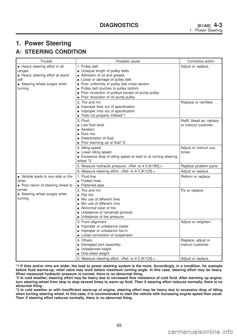
A: STEERING CONDITION
Trouble Possible cause Corrective action
IHeavy steering effort in all
ranges
IHeavy steering effort at stand
still
ISteering wheel surges when
turning.1. Pulley belt
IUnequal length of pulley belts
IAdhesion of oil and grease
ILoose or damage of pulley belt
IPoor uniformity of pulley belt cross section
IPulley belt touches to pulley bottom
IPoor revolution of pulleys except oil pump pulley
IPoor revolution of oil pump pulleyAdjust or replace.
2. Tire and rim
IImproper tires out of specification
IImproper rims out of specification
ITires not properly inflated*1Replace or reinflate.
3. Fluid
ILow fluid level
IAeration
IDust mix
IDeterioration of fluid
IPoor warming-up of fluid *2Refill, bleed air, replace
or instruct customer.
4. Idling speed
ILower idling speed
IExcessive drop of idling speed at start or at turning steering
wheel *3Adjust or instruct cus-
tomer.
5. Measure hydraulic pressure.
6. Measure steering effort.
IVehicle leads to one side or the
other.
IPoor return of steering wheel to
center
ISteering wheel surges when
turning.1. Fluid line
IFolded hose
IFlattened pipeReform or replace.
2. Tire and rim
IFlat tire
IMix use of different tires
IMix use of different rims
IAbnormal wear of tire
IUnbalance of remained grooves
IUnbalance of tire pressureFix or replace.
3. Front alignment
IImproper or unbalance caster
IImproper or unbalance toe-in
ILoose connection of suspensionAdjust or retighten.
4. Others
IDamaged joint assembly
IUnbalanced height
IOne-sided weightReplace, adjust or
instruct customer.
5. Measure steering effort.
*1 If tires and/or rims are wider, the load to power steering system is the more. Accordingly, in a condition, for example
before fluid warms-up, relief valve may work before maximum turning angle. In this case, steering effort may be heavy.
When measured hydraulic pressure is normal, there is no abnormal thing.
*2 In cold weather, steering effort may be heavy due to increased flow resistance of cold fluid. After warming up engine,
turn steering wheel from stop to stop several times to warm up fluid. Then if steering effort reduces normally, there is no
abnormal thing.
*3 In cold weather or with insufficient warm-up of engine, steering effort may be heavy due to excessive drop of idling
when turning steering wheel. In this case, it is recommended to start the vehicle with increasing engine speed than usual.
Then if steering effort reduces normally, there is no abnormal thing.
69
[K1A0]4-3DIAGNOSTICS
1. Power Steering
Page 864 of 1456
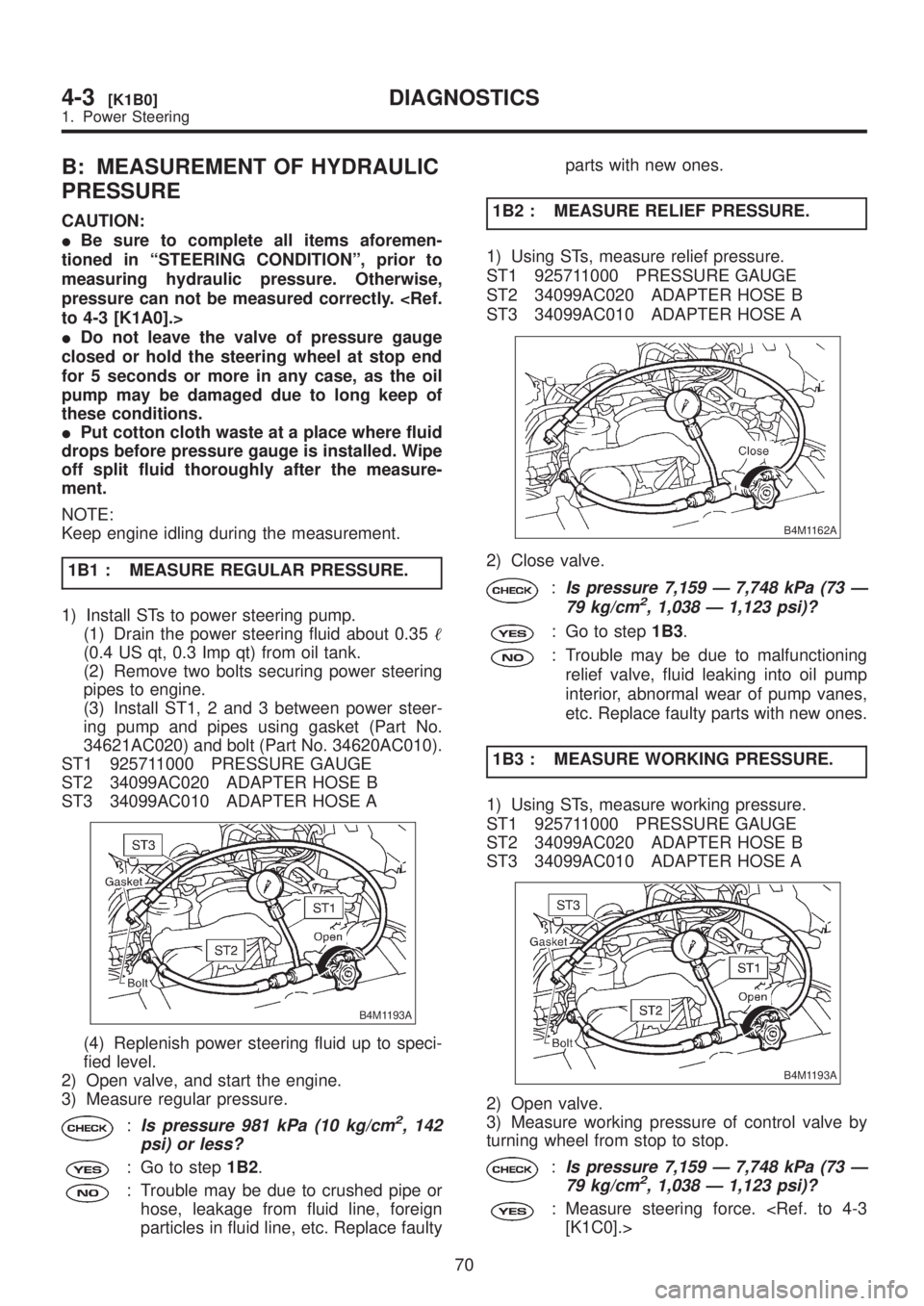
B: MEASUREMENT OF HYDRAULIC
PRESSURE
CAUTION:
IBe sure to complete all items aforemen-
tioned in ªSTEERING CONDITIONº, prior to
measuring hydraulic pressure. Otherwise,
pressure can not be measured correctly.
IDo not leave the valve of pressure gauge
closed or hold the steering wheel at stop end
for 5 seconds or more in any case, as the oil
pump may be damaged due to long keep of
these conditions.
IPut cotton cloth waste at a place where fluid
drops before pressure gauge is installed. Wipe
off split fluid thoroughly after the measure-
ment.
NOTE:
Keep engine idling during the measurement.
1B1 : MEASURE REGULAR PRESSURE.
1) Install STs to power steering pump.
(1) Drain the power steering fluid about 0.35
(0.4 US qt, 0.3 Imp qt) from oil tank.
(2) Remove two bolts securing power steering
pipes to engine.
(3) Install ST1, 2 and 3 between power steer-
ing pump and pipes using gasket (Part No.
34621AC020) and bolt (Part No. 34620AC010).
ST1 925711000 PRESSURE GAUGE
ST2 34099AC020 ADAPTER HOSE B
ST3 34099AC010 ADAPTER HOSE A
B4M1193A
(4) Replenish power steering fluid up to speci-
fied level.
2) Open valve, and start the engine.
3) Measure regular pressure.
:Is pressure 981 kPa (10 kg/cm2, 142
psi) or less?
: Go to step1B2.
: Trouble may be due to crushed pipe or
hose, leakage from fluid line, foreign
particles in fluid line, etc. Replace faultyparts with new ones.
1B2 : MEASURE RELIEF PRESSURE.
1) Using STs, measure relief pressure.
ST1 925711000 PRESSURE GAUGE
ST2 34099AC020 ADAPTER HOSE B
ST3 34099AC010 ADAPTER HOSE A
B4M1162A
2) Close valve.
:Is pressure 7,159 Ð 7,748 kPa (73 Ð
79 kg/cm2, 1,038 Ð 1,123 psi)?
: Go to step1B3.
: Trouble may be due to malfunctioning
relief valve, fluid leaking into oil pump
interior, abnormal wear of pump vanes,
etc. Replace faulty parts with new ones.
1B3 : MEASURE WORKING PRESSURE.
1) Using STs, measure working pressure.
ST1 925711000 PRESSURE GAUGE
ST2 34099AC020 ADAPTER HOSE B
ST3 34099AC010 ADAPTER HOSE A
B4M1193A
2) Open valve.
3) Measure working pressure of control valve by
turning wheel from stop to stop.
:Is pressure 7,159 Ð 7,748 kPa (73 Ð
79 kg/cm2, 1,038 Ð 1,123 psi)?
: Measure steering force.
70
4-3[K1B0]DIAGNOSTICS
1. Power Steering
Page 868 of 1456
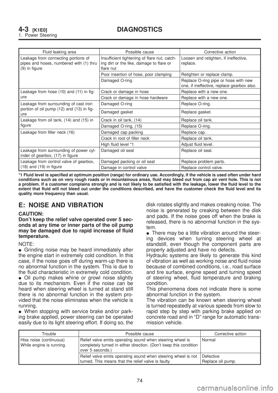
Fluid leaking area Possible cause Corrective action
Leakage from connecting portions of
pipes and hoses, numbered with (1) thru
(9) in figureInsufficient tightening of flare nut, catch-
ing dirt or the like, damage to flare or
flare nutLoosen and retighten, if ineffective,
replace.
Poor insertion of hose, poor clamping Retighten or replace clamp.
Damaged O-ring Replace O-ring pipe or hose with new
one, if ineffective, replace gearbox also.
Leakage from hose (10) and (11) in fig-
ureCrack or damage in hose Replace with a new one.
Crack or damage in hose hardware Replace with a new one.
Leakage from surrounding of cast iron
portion of oil pump (12) and (13) in fig-
ureDamaged O-ring Replace O-ring.
Damaged gasket Replace gasket.
Leakage from oil tank, (14) and (15) in
figureCrack in oil tank, (14) Replace oil tank.
Damaged O-ring, (15) Replace O-ring.
Leakage from filler neck (16) Damaged cap packing Replace cap.
Crack in root of filler neck Replace oil tank.
High fluid level *1 Adjust fluid level.
Leakage from surrounding of power cyl-
inder of gearbox, (17) in figureDamaged oil seal Replace oil seal.
Leakage from control valve of gearbox,
(18) and (19) in figureDamaged packing or oil seal Replace problem parts.
Damage in control valve Replace control valve.
*1 Fluid level is specified at optimum position (range) for ordinary use. Accordingly, if the vehicle is used often under hard
conditions such as on very rough roads or in mountainous areas, fluid may bleed out from cap air vent hole. This is not
a problem. If a customer complains strongly and is not likely to be satisfied with the leakage, lower the fluid level to the
extent that fluid will not bleed out under the conditions described, and have the customer check the fluid level and its
quality more frequency than usual.
E: NOISE AND VIBRATION
CAUTION:
Don't keep the relief valve operated over 5 sec-
onds at any time or inner parts of the oil pump
may be damaged due to rapid increase of fluid
temperature.
NOTE:
IGrinding noise may be heard immediately after
the engine start in extremely cold condition. In this
case, if the noise goes off during warm-up there is
no abnormal function in the system. This is due to
the fluid characteristic in extremely cold condition.
IOil pump makes whine or growl noise slightly
due to its mechanism. Even if the noise can be
heard when steering wheel is turned at stand still
there is no abnormal function in the system pro-
vided that the noise eliminates when the vehicle is
running.
IWhen stopping with service brake and/or park-
ing brake applied, power steering can be operated
easily due to its light steering effort. If doing so, thedisk rotates slightly and makes creaking noise. The
noise is generated by creaking between the disk
and pads. If the noise goes off when the brake is
released, there is no abnormal function in the sys-
tem.
IThere may be a little vibration around the steer-
ing devices when turning steering wheel at
standstill, even though the component parts are
properly adjusted and have no defects.
Hydraulic systems are likely to generate this kind
of vibration as well as working noise and fluid noise
because of combined conditions, i.e., road surface
and tire surface, engine speed and turning speed
of steering wheel, fluid temperature and braking
condition.
This phenomena does not indicate there is some
abnormal function in the system.
The vibration can be known when steering wheel
is turned repeatedly at various speeds from slow to
rapid step by step with parking brake applied on
concrete road and in ªDº range for automatic trans-
mission vehicle.
Trouble Possible cause Corrective action
Hiss noise (continuous)
While engine is running.Relief valve emits operating sound when steering wheel is
completely turned in either direction. (Don't keep this condition
over 5 seconds.)Normal
Relief valve emits operating sound when steering wheel is not
turned. This means that the relief valve is faulty.Defective
Replace oil pump.
74
4-3[K1E0]DIAGNOSTICS
1. Power Steering
Page 914 of 1456
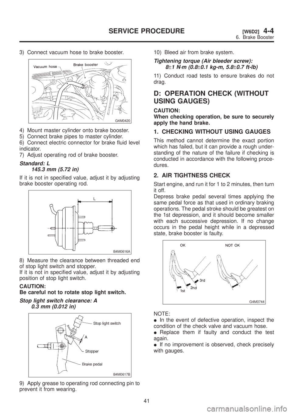
3) Connect vacuum hose to brake booster.
G4M0420
4) Mount master cylinder onto brake booster.
5) Connect brake pipes to master cylinder.
6) Connect electric connector for brake fluid level
indicator.
7) Adjust operating rod of brake booster.
Standard: L
145.3 mm (5.72 in)
If it is not in specified value, adjust it by adjusting
brake booster operating rod.
B4M0616A
8) Measure the clearance between threaded end
of stop light switch and stopper.
If it is not in specified value, adjust it by adjusting
position of stop light switch.
CAUTION:
Be careful not to rotate stop light switch.
Stop light switch clearance: A
0.3 mm (0.012 in)
B4M0617B
9) Apply grease to operating rod connecting pin to
prevent it from wearing.10) Bleed air from brake system.
Tightening torque (Air bleeder screw):
8
±1 N´m (0.8±0.1 kg-m, 5.8±0.7 ft-lb)
11) Conduct road tests to ensure brakes do not
drag.
D: OPERATION CHECK (WITHOUT
USING GAUGES)
CAUTION:
When checking operation, be sure to securely
apply the hand brake.
1. CHECKING WITHOUT USING GAUGES
This method cannot determine the exact portion
which has failed, but it can provide a rough under-
standing of the nature of the failure if checking is
conducted in accordance with the following proce-
dures.
2. AIR TIGHTNESS CHECK
Start engine, and run it for 1 to 2 minutes, then turn
it off.
Depress brake pedal several times applying the
same pedal force as that used in ordinary braking
operations. The pedal stroke should be greatest on
the 1st depression, and it should become smaller
with each successive depression. If no change
occurs in the pedal height while in a depressed
state, brake booster is faulty.
G4M0744
NOTE:
IIn the event of defective operation, inspect the
condition of the check valve and vacuum hose.
IReplace them if faulty and conduct the test
again.
IIf no improvement is observed, check precisely
with gauges.
41
[W6D2]4-4SERVICE PROCEDURE
6. Brake Booster
Page 915 of 1456
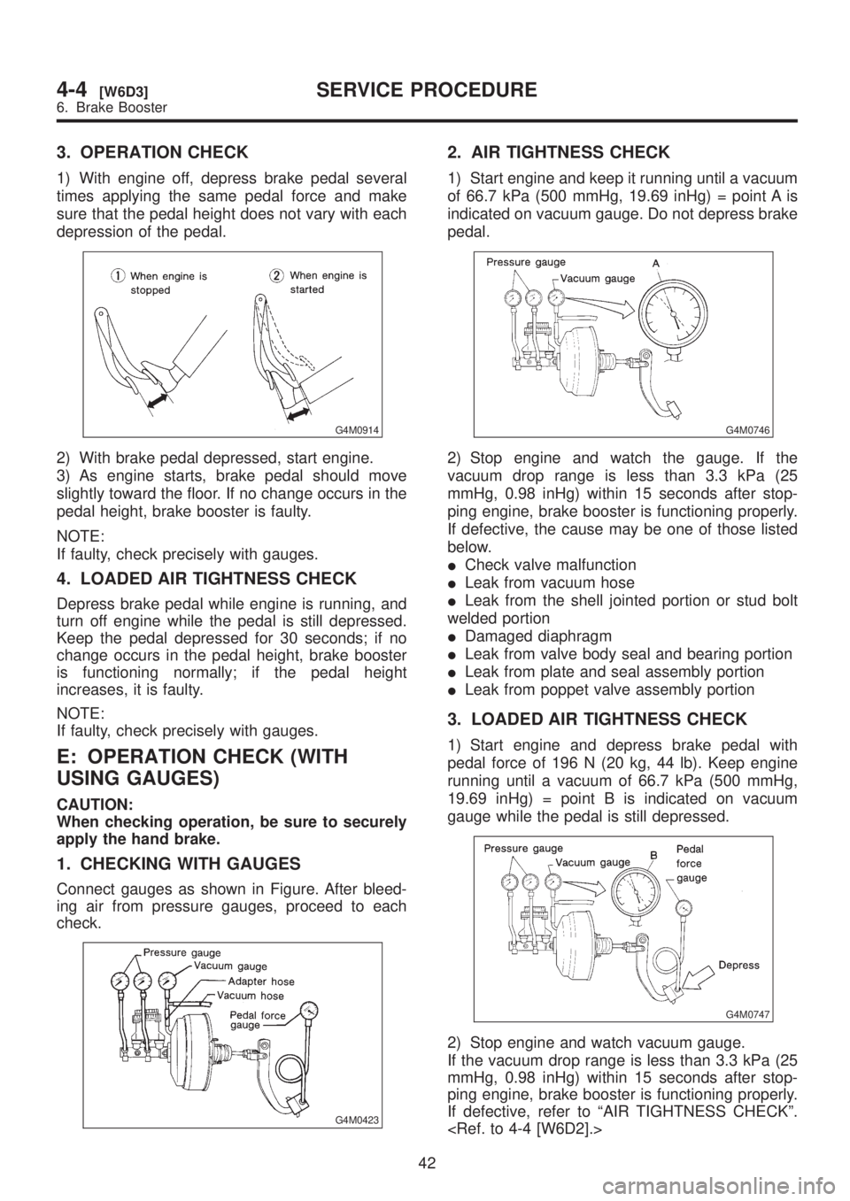
3. OPERATION CHECK
1) With engine off, depress brake pedal several
times applying the same pedal force and make
sure that the pedal height does not vary with each
depression of the pedal.
G4M0914
2) With brake pedal depressed, start engine.
3) As engine starts, brake pedal should move
slightly toward the floor. If no change occurs in the
pedal height, brake booster is faulty.
NOTE:
If faulty, check precisely with gauges.
4. LOADED AIR TIGHTNESS CHECK
Depress brake pedal while engine is running, and
turn off engine while the pedal is still depressed.
Keep the pedal depressed for 30 seconds; if no
change occurs in the pedal height, brake booster
is functioning normally; if the pedal height
increases, it is faulty.
NOTE:
If faulty, check precisely with gauges.
E: OPERATION CHECK (WITH
USING GAUGES)
CAUTION:
When checking operation, be sure to securely
apply the hand brake.
1. CHECKING WITH GAUGES
Connect gauges as shown in Figure. After bleed-
ing air from pressure gauges, proceed to each
check.
G4M0423
2. AIR TIGHTNESS CHECK
1) Start engine and keep it running until a vacuum
of 66.7 kPa (500 mmHg, 19.69 inHg) = point A is
indicated on vacuum gauge. Do not depress brake
pedal.
G4M0746
2) Stop engine and watch the gauge. If the
vacuum drop range is less than 3.3 kPa (25
mmHg, 0.98 inHg) within 15 seconds after stop-
ping engine, brake booster is functioning properly.
If defective, the cause may be one of those listed
below.
ICheck valve malfunction
ILeak from vacuum hose
ILeak from the shell jointed portion or stud bolt
welded portion
IDamaged diaphragm
ILeak from valve body seal and bearing portion
ILeak from plate and seal assembly portion
ILeak from poppet valve assembly portion
3. LOADED AIR TIGHTNESS CHECK
1) Start engine and depress brake pedal with
pedal force of 196 N (20 kg, 44 lb). Keep engine
running until a vacuum of 66.7 kPa (500 mmHg,
19.69 inHg) = point B is indicated on vacuum
gauge while the pedal is still depressed.
G4M0747
2) Stop engine and watch vacuum gauge.
If the vacuum drop range is less than 3.3 kPa (25
mmHg, 0.98 inHg) within 15 seconds after stop-
ping engine, brake booster is functioning properly.
If defective, refer to ªAIR TIGHTNESS CHECKº.
42
4-4[W6D3]SERVICE PROCEDURE
6. Brake Booster
Page 920 of 1456
Tightening torque:
18
±5 N´m (1.8±0.5 kg-m, 13.0±3.6 ft-lb)
2) Connect brake pipes to PHV.
Tightening torque:
15+3/þ2N´m (1.5+0.3/þ0.2kg-m, 10.8+2.2/þ1.4ft-lb)
CAUTION:
Confirm that brake pipes are not deformed
and/or damaged. Replace them with new ones
if necessary.
3) Install PHV cable to PHV stay.
CAUTION:
If cable clamp (and clips) is damaged, replace
it with a new one.
4) Connect PHV cable with clips.
NOTE:
Avoid sharp bending of PHV cable as it may cause
breakage.
5) Install PHV cable onto cable bracket on engine.
6) Apply grease to the following points.
IHook portion of return spring
ICable end portion of lever
Grease:
SUNLIGHT 2 (Part No. 003602010)
7) Be sure to bleed air from the system.
CAUTION:
After replacing PHV cable or clutch cable with
new one, operate clutch pedal about 30 times
as a running-in operation prior to adjustment.
D: ADJUSTMENTS
Confirm stopping and starting performances by
activating hill holder on an uphill road of 3É or
higher inclination.
1) If vehicle does not stop;
Tighten adjusting nut of PHV cable.
2) If vehicle does not start properly;
ICase A Ð When hill holder is released later than
engagement of clutch pedal (Engine tends to
stall.):
Loosen adjusting nut gradually until smooth start-
ing is enabled.
ICase B Ð When hill holder is released earlier
than engagement of clutch pedal (Vehicle slips
down slightly.):
Tighten adjusting nut so that hill holder is released
later than engagement of clutch pedal (status in
Case A). Then make adjustment the same as in
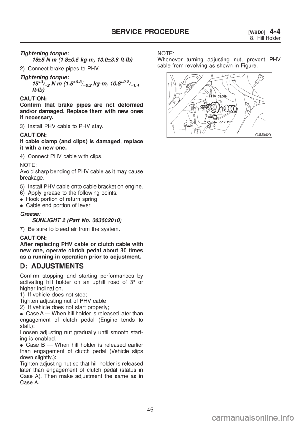
Case A.NOTE:
Whenever turning adjusting nut, prevent PHV
cable from revolving as shown in Figure.
G4M0429
45
[W8D0]4-4SERVICE PROCEDURE
8. Hill Holder