transmission oil SUBARU LEGACY 1999 Service Repair Manual
[x] Cancel search | Manufacturer: SUBARU, Model Year: 1999, Model line: LEGACY, Model: SUBARU LEGACY 1999Pages: 1456, PDF Size: 59.93 MB
Page 260 of 1456
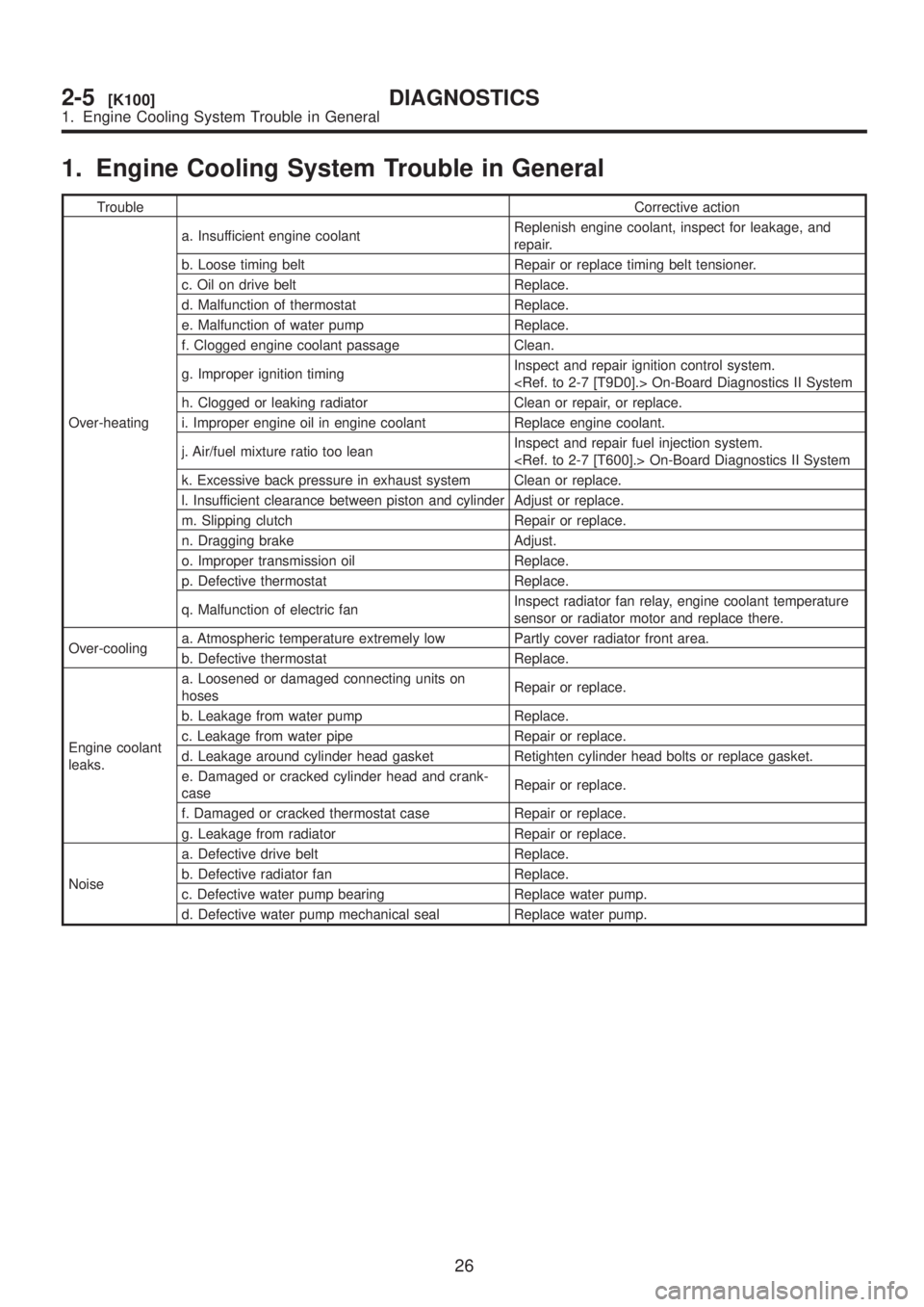
1. Engine Cooling System Trouble in General
TroubleCorrective action
Over-heatinga. Insufficient engine coolantReplenish engine coolant, inspect for leakage, and
repair.
b. Loose timing belt Repair or replace timing belt tensioner.
c. Oil on drive belt Replace.
d. Malfunction of thermostat Replace.
e. Malfunction of water pump Replace.
f. Clogged engine coolant passage Clean.
g. Improper ignition timingInspect and repair ignition control system.
h. Clogged or leaking radiator Clean or repair, or replace.
i. Improper engine oil in engine coolant Replace engine coolant.
j. Air/fuel mixture ratio too leanInspect and repair fuel injection system.
k. Excessive back pressure in exhaust system Clean or replace.
l. Insufficient clearance between piston and cylinder Adjust or replace.
m. Slipping clutch Repair or replace.
n. Dragging brake Adjust.
o. Improper transmission oil Replace.
p. Defective thermostat Replace.
q. Malfunction of electric fanInspect radiator fan relay, engine coolant temperature
sensor or radiator motor and replace there.
Over-coolinga. Atmospheric temperature extremely low Partly cover radiator front area.
b. Defective thermostat Replace.
Engine coolant
leaks.a. Loosened or damaged connecting units on
hosesRepair or replace.
b. Leakage from water pump Replace.
c. Leakage from water pipe Repair or replace.
d. Leakage around cylinder head gasket Retighten cylinder head bolts or replace gasket.
e. Damaged or cracked cylinder head and crank-
caseRepair or replace.
f. Damaged or cracked thermostat case Repair or replace.
g. Leakage from radiator Repair or replace.
Noisea. Defective drive belt Replace.
b. Defective radiator fan Replace.
c. Defective water pump bearing Replace water pump.
d. Defective water pump mechanical seal Replace water pump.
26
2-5[K100]DIAGNOSTICS
1. Engine Cooling System Trouble in General
Page 421 of 1456
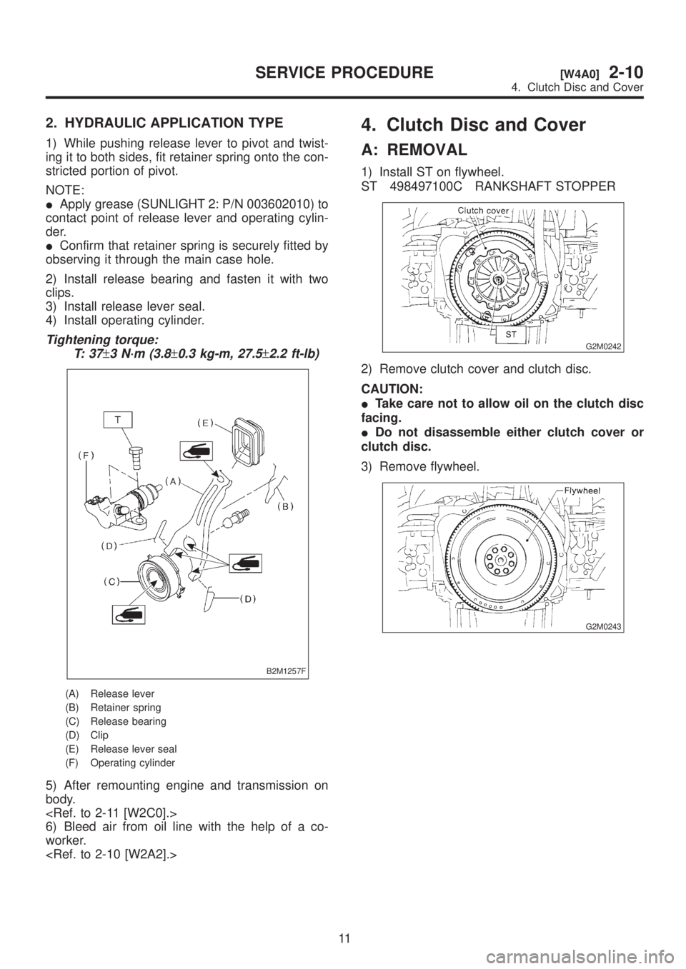
2. HYDRAULIC APPLICATION TYPE
1) While pushing release lever to pivot and twist-
ing it to both sides, fit retainer spring onto the con-
stricted portion of pivot.
NOTE:
IApply grease (SUNLIGHT 2: P/N 003602010) to
contact point of release lever and operating cylin-
der.
IConfirm that retainer spring is securely fitted by
observing it through the main case hole.
2) Install release bearing and fasten it with two
clips.
3) Install release lever seal.
4) Install operating cylinder.
Tightening torque:
T: 3 7
±3 N´m (3.8±0.3 kg-m, 27.5±2.2 ft-lb)
B2M1257F
(A) Release lever
(B) Retainer spring
(C) Release bearing
(D) Clip
(E) Release lever seal
(F) Operating cylinder
5) After remounting engine and transmission on
body.
6) Bleed air from oil line with the help of a co-
worker.
4. Clutch Disc and Cover
A: REMOVAL
1) Install ST on flywheel.
ST 498497100C RANKSHAFT STOPPER
G2M0242
2) Remove clutch cover and clutch disc.
CAUTION:
ITake care not to allow oil on the clutch disc
facing.
IDo not disassemble either clutch cover or
clutch disc.
3) Remove flywheel.
G2M0243
11
[W4A0]2-10SERVICE PROCEDURE
4. Clutch Disc and Cover
Page 422 of 1456
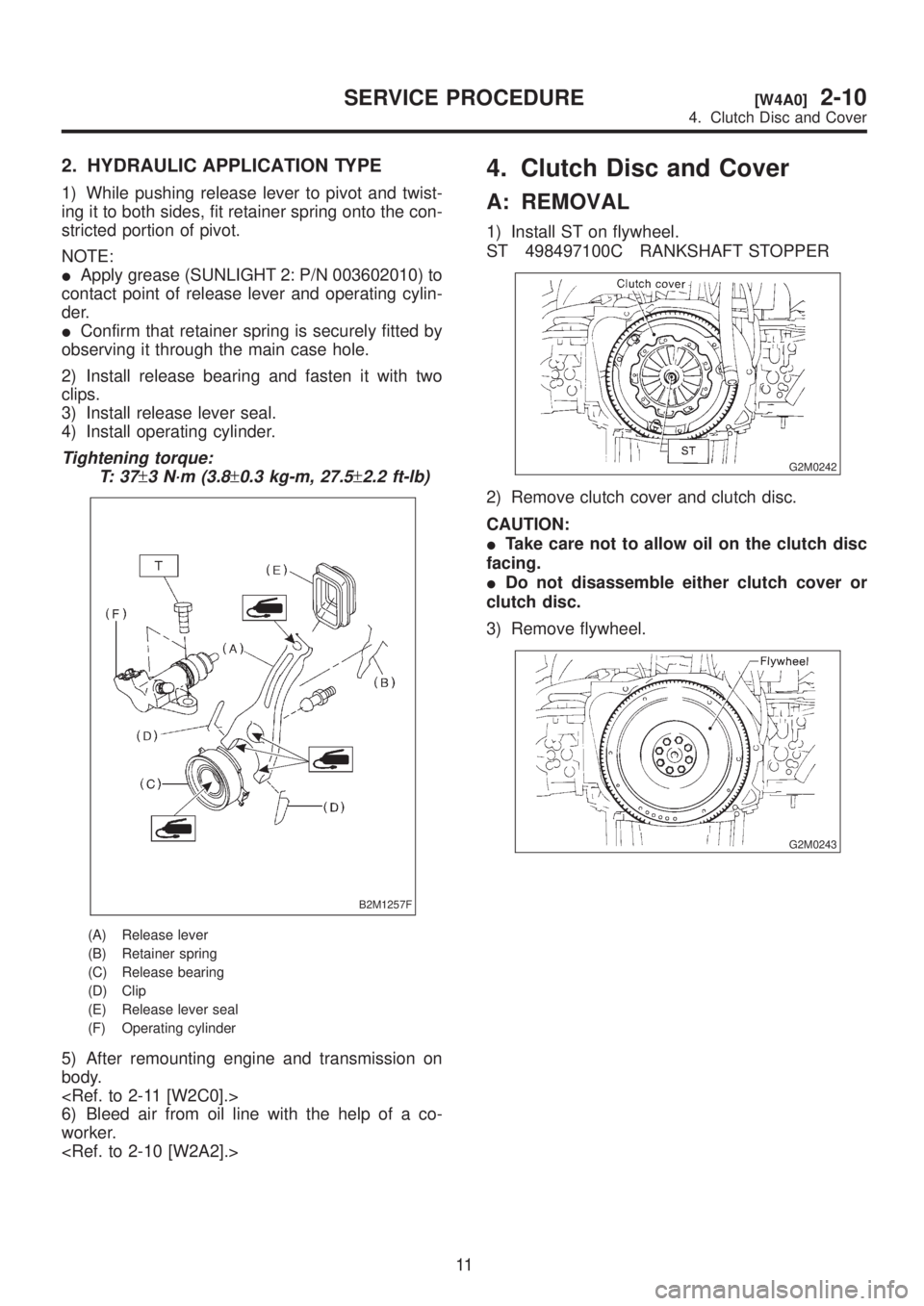
2. HYDRAULIC APPLICATION TYPE
1) While pushing release lever to pivot and twist-
ing it to both sides, fit retainer spring onto the con-
stricted portion of pivot.
NOTE:
IApply grease (SUNLIGHT 2: P/N 003602010) to
contact point of release lever and operating cylin-
der.
IConfirm that retainer spring is securely fitted by
observing it through the main case hole.
2) Install release bearing and fasten it with two
clips.
3) Install release lever seal.
4) Install operating cylinder.
Tightening torque:
T: 3 7
±3 N´m (3.8±0.3 kg-m, 27.5±2.2 ft-lb)
B2M1257F
(A) Release lever
(B) Retainer spring
(C) Release bearing
(D) Clip
(E) Release lever seal
(F) Operating cylinder
5) After remounting engine and transmission on
body.
6) Bleed air from oil line with the help of a co-
worker.
4. Clutch Disc and Cover
A: REMOVAL
1) Install ST on flywheel.
ST 498497100C RANKSHAFT STOPPER
G2M0242
2) Remove clutch cover and clutch disc.
CAUTION:
ITake care not to allow oil on the clutch disc
facing.
IDo not disassemble either clutch cover or
clutch disc.
3) Remove flywheel.
G2M0243
11
[W4A0]2-10SERVICE PROCEDURE
4. Clutch Disc and Cover
Page 423 of 1456
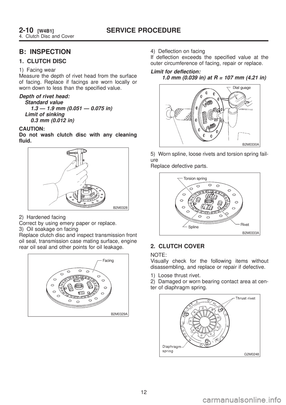
B: INSPECTION
1. CLUTCH DISC
1) Facing wear
Measure the depth of rivet head from the surface
of facing. Replace if facings are worn locally or
worn down to less than the specified value.
Depth of rivet head:
Standard value
1.3 Ð 1.9 mm (0.051 Ð 0.075 in)
Limit of sinking
0.3 mm (0.012 in)
CAUTION:
Do not wash clutch disc with any cleaning
fluid.
B2M0328
2) Hardened facing
Correct by using emery paper or replace.
3) Oil soakage on facing
Replace clutch disc and inspect transmission front
oil seal, transmission case mating surface, engine
rear oil seal and other points for oil leakage.
B2M0329A
4) Deflection on facing
If deflection exceeds the specified value at the
outer circumference of facing, repair or replace.
Limit for deflection:
1.0 mm (0.039 in) at R = 107 mm (4.21 in)
B2M0330A
5) Worn spline, loose rivets and torsion spring fail-
ure
Replace defective parts.
B2M0333A
2. CLUTCH COVER
NOTE:
Visually check for the following items without
disassembling, and replace or repair if defective.
1) Loose thrust rivet.
2) Damaged or worn bearing contact area at cen-
ter of diaphragm spring.
G2M0248
12
2-10[W4B1]SERVICE PROCEDURE
4. Clutch Disc and Cover
Page 430 of 1456
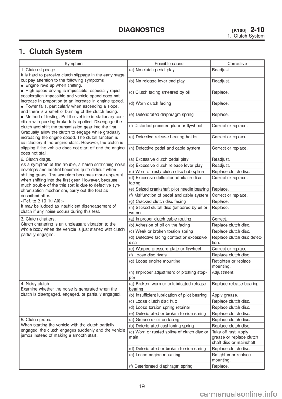
1. Clutch System
Symptom Possible cause Corrective
1. Clutch slippage.
It is hard to perceive clutch slippage in the early stage,
but pay attention to the following symptoms
IEngine revs up when shifting.
IHigh speed driving is impossible; especially rapid
acceleration impossible and vehicle speed does not
increase in proportion to an increase in engine speed.
IPower falls, particularly when ascending a slope,
and there is a smell of burning of the clutch facing.
IMethod of testing: Put the vehicle in stationary con-
dition with parking brake fully applied. Disengage the
clutch and shift the transmission gear into the first.
Gradually allow the clutch to engage while gradually
increasing the engine speed. The clutch function is
satisfactory if the engine stalls. However, the clutch is
slipping if the vehicle does not start off and the engine
does not stall.(a) No clutch pedal play Readjust.
(b) No release lever end play Readjust.
(c) Clutch facing smeared by oil Replace.
(d) Worn clutch facing Replace.
(e) Deteriorated diaphragm spring Replace.
(f) Distorted pressure plate or flywheel Correct or replace.
(g) Defective release bearing holder Correct or replace.
(h) Defective pedal and cable system Correct or replace.
2. Clutch drags.
As a symptom of this trouble, a harsh scratching noise
develops and control becomes quite difficult when
shifting gears. The symptom becomes more apparent
when shifting into the first gear. However, because
much trouble of the this sort is due to defective syn-
chronization mechanism, carry out the test as
described after.
It may be judged as insufficient disengagement of
clutch if any noise occurs during this test.(a) Excessive clutch pedal play Readjust.
(b) Excessive clutch release lever play Readjust.
(c) Worn or rusty clutch disc hub spline Replace clutch disc.
(d) Excessive deflection of clutch disc
facingCorrect or replace.
(e) Seized crankshaft pilot needle bearing Replace.
(f) Malfunction of pedal and cable system Correct or replace.
(g) Cracked clutch disc facing Replace.
(h) Sticked clutch disc (smeared by oil or
water)Replace.
3. Clutch chatters.
Clutch chattering is an unpleasant vibration to the
whole body when the vehicle is just started with clutch
partially engaged.(a) Improper clutch cable routing Correct.
(b) Adhesion of oil on the facing Replace clutch disc.
(c) Weak or broken torsion spring Replace clutch disc.
(d) Defective facing contact or excessive
discReplace clutch disc defec-
tion.
(e) Warped pressure plate or flywheel Correct or replace.
(f) Loose disc rivets Replace clutch disc.
(g) Loose engine mounting Retighten or replace
mounting.
(h) Improper adjustment of pitching stop-
perAdjustment.
4. Noisy clutch
Examine whether the noise is generated when the
clutch is disengaged, engaged, or partially engaged.(a) Broken, worn or unlubricated release
bearingReplace release bearing.
(b) Insufficient lubrication of pilot bearing Apply grease.
(c) Loose clutch disc hub Replace clutch disc.
(d) Loose torsion spring retainer Replace clutch disc.
(e) Deteriorated or broken torsion spring Replace clutch disc.
5. Clutch grabs.
When starting the vehicle with the clutch partially
engaged, the clutch engages suddenly and the vehicle
jumps instead of making a smooth start.(a) Grease or oil on facing Replace clutch disc.
(b) Deteriorated cushioning spring Replace clutch disc.
(c) Worn or rusted spline of clutch disc or
mainTake off rust, apply
grease or replace clutch
shaft disc or mainshaft.
(d) Deteriorated or broken torsion spring Replace clutch disc.
(e) Loose engine mounting Retighten or replace
mounting.
(f) Deteriorated diaphragm spring Replace.
19
[K100]2-10DIAGNOSTICS
1. Clutch System
Page 439 of 1456
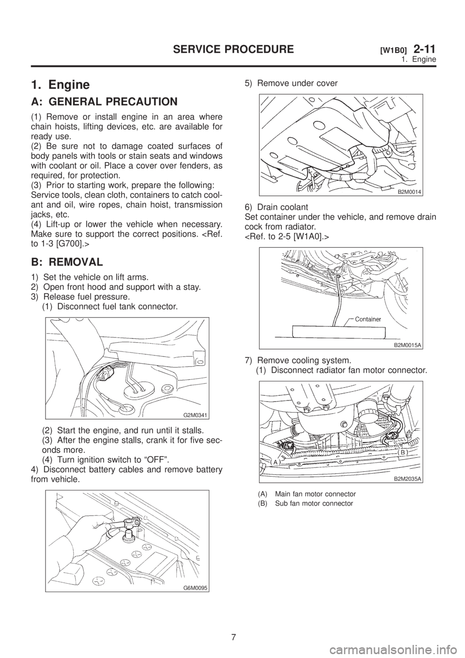
1. Engine
A: GENERAL PRECAUTION
(1) Remove or install engine in an area where
chain hoists, lifting devices, etc. are available for
ready use.
(2) Be sure not to damage coated surfaces of
body panels with tools or stain seats and windows
with coolant or oil. Place a cover over fenders, as
required, for protection.
(3) Prior to starting work, prepare the following:
Service tools, clean cloth, containers to catch cool-
ant and oil, wire ropes, chain hoist, transmission
jacks, etc.
(4) Lift-up or lower the vehicle when necessary.
Make sure to support the correct positions.
B: REMOVAL
1) Set the vehicle on lift arms.
2) Open front hood and support with a stay.
3) Release fuel pressure.
(1) Disconnect fuel tank connector.
G2M0341
(2) Start the engine, and run until it stalls.
(3) After the engine stalls, crank it for five sec-
onds more.
(4) Turn ignition switch to ªOFFº.
4) Disconnect battery cables and remove battery
from vehicle.
G6M0095
5) Remove under cover
B2M0014
6) Drain coolant
Set container under the vehicle, and remove drain
cock from radiator.
B2M0015A
7) Remove cooling system.
(1) Disconnect radiator fan motor connector.
B2M2035A
(A) Main fan motor connector
(B) Sub fan motor connector
7
[W1B0]2-11SERVICE PROCEDURE
1. Engine
Page 448 of 1456
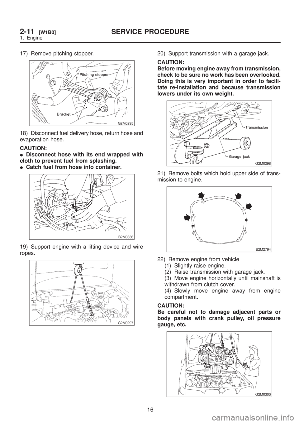
17) Remove pitching stopper.
G2M0295
18) Disconnect fuel delivery hose, return hose and
evaporation hose.
CAUTION:
IDisconnect hose with its end wrapped with
cloth to prevent fuel from splashing.
ICatch fuel from hose into container.
B2M0336
19) Support engine with a lifting device and wire
ropes.
G2M0297
20) Support transmission with a garage jack.
CAUTION:
Before moving engine away from transmission,
check to be sure no work has been overlooked.
Doing this is very important in order to facili-
tate re-installation and because transmission
lowers under its own weight.
G2M0298
21) Remove bolts which hold upper side of trans-
mission to engine.
B2M2794
22) Remove engine from vehicle
(1) Slightly raise engine.
(2) Raise transmission with garage jack.
(3) Move engine horizontally until mainshaft is
withdrawn from clutch cover.
(4) Slowly move engine away from engine
compartment.
CAUTION:
Be careful not to damage adjacent parts or
body panels with crank pulley, oil pressure
gauge, etc.
G2M0300
16
2-11[W1B0]SERVICE PROCEDURE
1. Engine
Page 449 of 1456
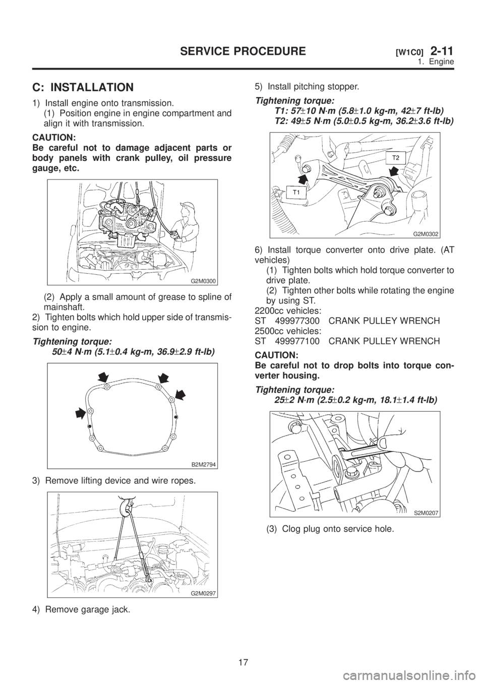
C: INSTALLATION
1) Install engine onto transmission.
(1) Position engine in engine compartment and
align it with transmission.
CAUTION:
Be careful not to damage adjacent parts or
body panels with crank pulley, oil pressure
gauge, etc.
G2M0300
(2) Apply a small amount of grease to spline of
mainshaft.
2) Tighten bolts which hold upper side of transmis-
sion to engine.
Tightening torque:
50
±4 N´m (5.1±0.4 kg-m, 36.9±2.9 ft-lb)
B2M2794
3) Remove lifting device and wire ropes.
G2M0297
4) Remove garage jack.5) Install pitching stopper.
Tightening torque:
T1: 57
±10 N´m (5.8±1.0 kg-m, 42±7 ft-lb)
T2: 49
±5 N´m (5.0±0.5 kg-m, 36.2±3.6 ft-lb)
G2M0302
6) Install torque converter onto drive plate. (AT
vehicles)
(1) Tighten bolts which hold torque converter to
drive plate.
(2) Tighten other bolts while rotating the engine
by using ST.
2200cc vehicles:
ST 499977300 CRANK PULLEY WRENCH
2500cc vehicles:
ST 499977100 CRANK PULLEY WRENCH
CAUTION:
Be careful not to drop bolts into torque con-
verter housing.
Tightening torque:
25
±2 N´m (2.5±0.2 kg-m, 18.1±1.4 ft-lb)
S2M0207
(3) Clog plug onto service hole.
17
[W1C0]2-11SERVICE PROCEDURE
1. Engine
Page 453 of 1456
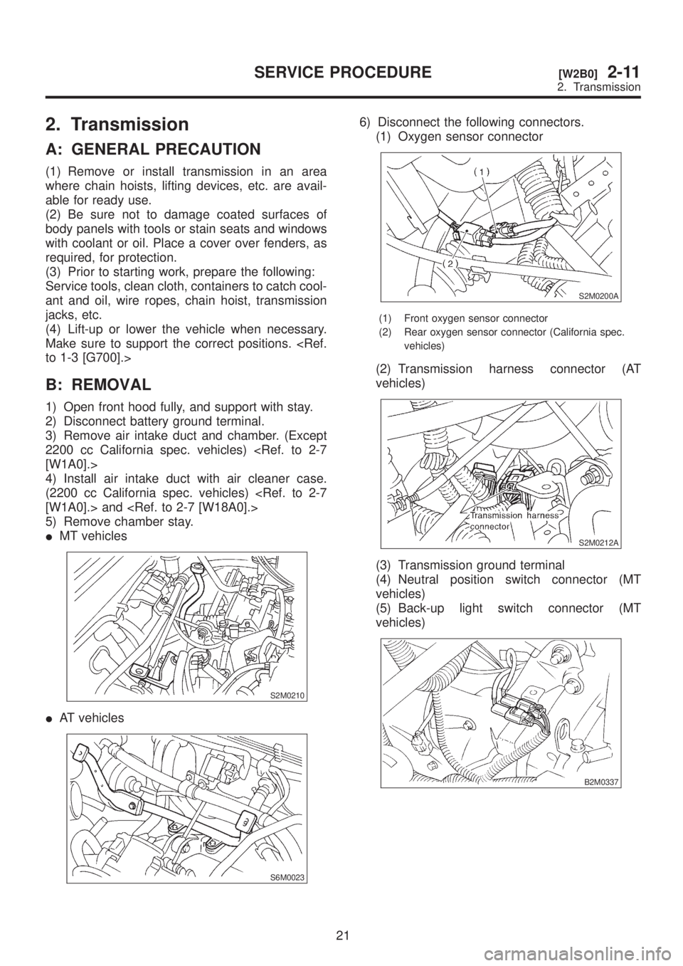
2. Transmission
A: GENERAL PRECAUTION
(1) Remove or install transmission in an area
where chain hoists, lifting devices, etc. are avail-
able for ready use.
(2) Be sure not to damage coated surfaces of
body panels with tools or stain seats and windows
with coolant or oil. Place a cover over fenders, as
required, for protection.
(3) Prior to starting work, prepare the following:
Service tools, clean cloth, containers to catch cool-
ant and oil, wire ropes, chain hoist, transmission
jacks, etc.
(4) Lift-up or lower the vehicle when necessary.
Make sure to support the correct positions.
B: REMOVAL
1) Open front hood fully, and support with stay.
2) Disconnect battery ground terminal.
3) Remove air intake duct and chamber. (Except
2200 cc California spec. vehicles)
4) Install air intake duct with air cleaner case.
(2200 cc California spec. vehicles)
5) Remove chamber stay.
IMT vehicles
S2M0210
IAT vehicles
S6M0023
6) Disconnect the following connectors.
(1) Oxygen sensor connector
S2M0200A
(1) Front oxygen sensor connector
(2) Rear oxygen sensor connector (California spec.
vehicles)
(2) Transmission harness connector (AT
vehicles)
S2M0212A
(3) Transmission ground terminal
(4) Neutral position switch connector (MT
vehicles)
(5) Back-up light switch connector (MT
vehicles)
B2M0337
21
[W2B0]2-11SERVICE PROCEDURE
2. Transmission
Page 457 of 1456
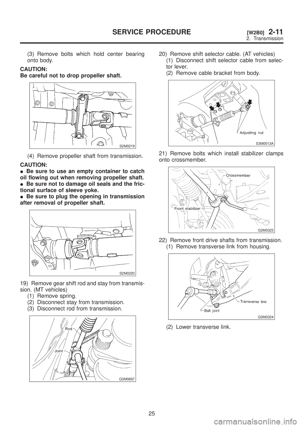
(3) Remove bolts which hold center bearing
onto body.
CAUTION:
Be careful not to drop propeller shaft.
S2M0219
(4) Remove propeller shaft from transmission.
CAUTION:
IBe sure to use an empty container to catch
oil flowing out when removing propeller shaft.
IBe sure not to damage oil seals and the fric-
tional surface of sleeve yoke.
IBe sure to plug the opening in transmission
after removal of propeller shaft.
S2M0220
19) Remove gear shift rod and stay from transmis-
sion. (MT vehicles)
(1) Remove spring.
(2) Disconnect stay from transmission.
(3) Disconnect rod from transmission.
G3M0697
20) Remove shift selector cable. (AT vehicles)
(1) Disconnect shift selector cable from selec-
tor lever.
(2) Remove cable bracket from body.
S3M0013A
21) Remove bolts which install stabilizer clamps
onto crossmember.
G2M0323
22) Remove front drive shafts from transmission.
(1) Remove transverse link from housing.
G2M0324
(2) Lower transverse link.
25
[W2B0]2-11SERVICE PROCEDURE
2. Transmission