water pump SUBARU LEGACY 1999 Service Repair Manual
[x] Cancel search | Manufacturer: SUBARU, Model Year: 1999, Model line: LEGACY, Model: SUBARU LEGACY 1999Pages: 1456, PDF Size: 59.93 MB
Page 62 of 1456
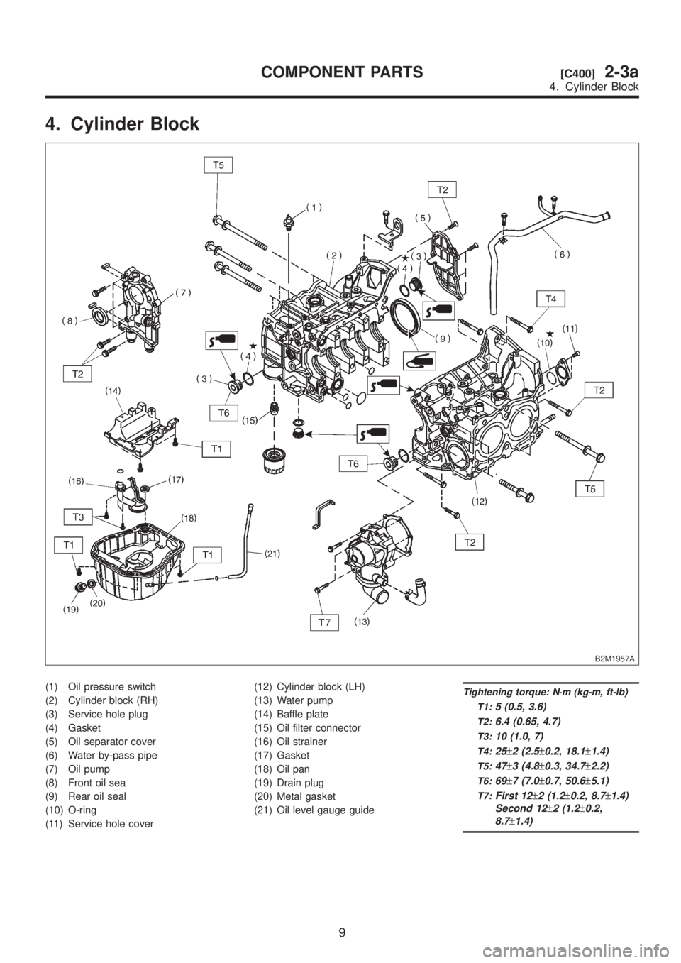
4. Cylinder Block
B2M1957A
(1) Oil pressure switch
(2) Cylinder block (RH)
(3) Service hole plug
(4) Gasket
(5) Oil separator cover
(6) Water by-pass pipe
(7) Oil pump
(8) Front oil sea
(9) Rear oil seal
(10) O-ring
(11) Service hole cover(12) Cylinder block (LH)
(13) Water pump
(14) Baffle plate
(15) Oil filter connector
(16) Oil strainer
(17) Gasket
(18) Oil pan
(19) Drain plug
(20) Metal gasket
(21) Oil level gauge guideTightening torque: N´m (kg-m, ft-lb)
T1:
5 (0.5, 3.6)
T2:6.4 (0.65, 4.7)
T3:10 (1.0, 7)
T4:25±2 (2.5±0.2, 18.1±1.4)
T5:47±3 (4.8±0.3, 34.7±2.2)
T6:69±7 (7.0±0.7, 50.6±5.1)
T7:First 12±2 (1.2±0.2, 8.7±1.4)
Second 12
±2 (1.2±0.2,
8.7
±1.4)
9
[C400]2-3aCOMPONENT PARTS
4. Cylinder Block
Page 106 of 1456
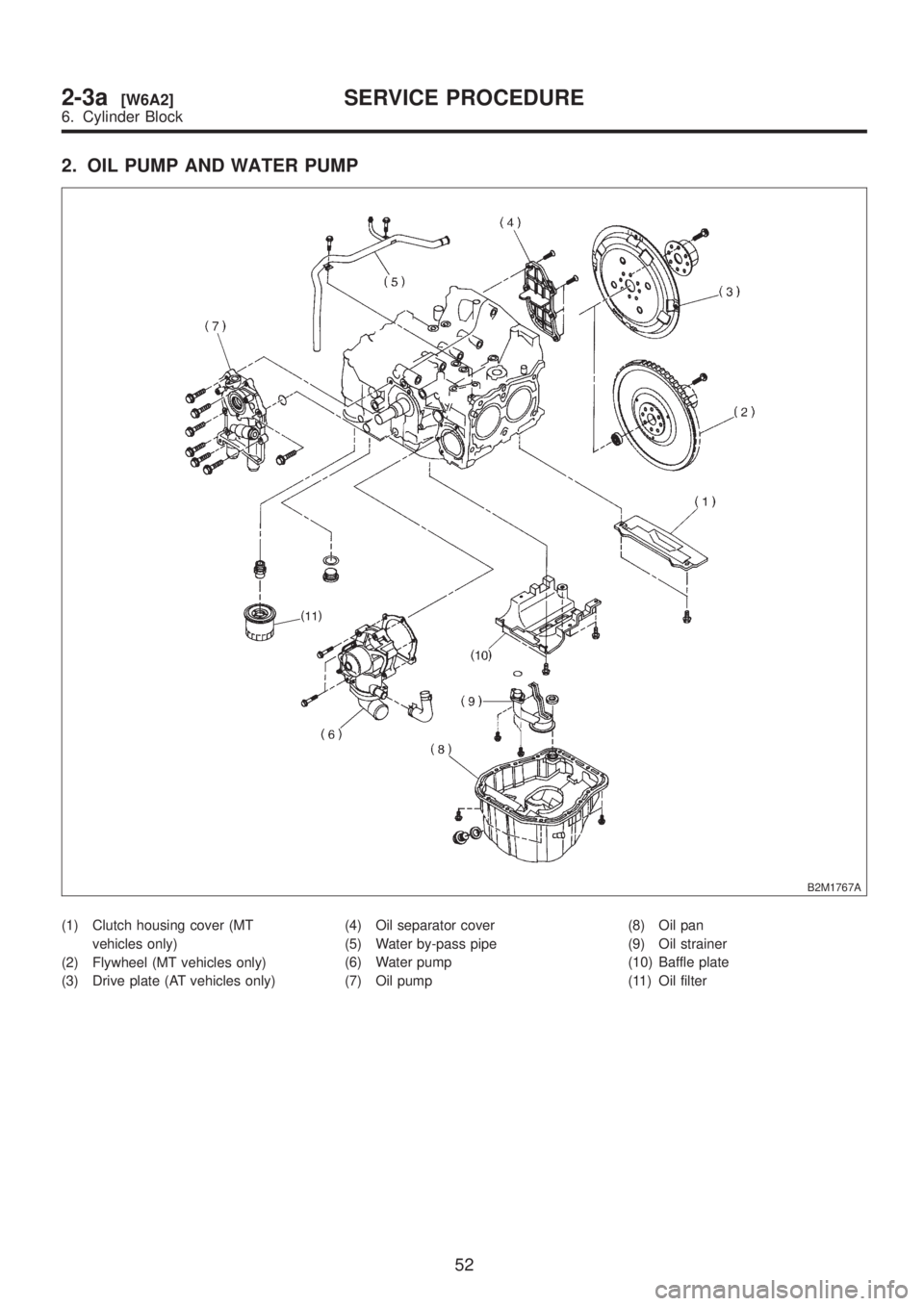
2. OIL PUMP AND WATER PUMP
B2M1767A
(1) Clutch housing cover (MT
vehicles only)
(2) Flywheel (MT vehicles only)
(3) Drive plate (AT vehicles only)(4) Oil separator cover
(5) Water by-pass pipe
(6) Water pump
(7) Oil pump(8) Oil pan
(9) Oil strainer
(10) Baffle plate
(11) Oil filter
52
2-3a[W6A2]SERVICE PROCEDURE
6. Cylinder Block
Page 107 of 1456
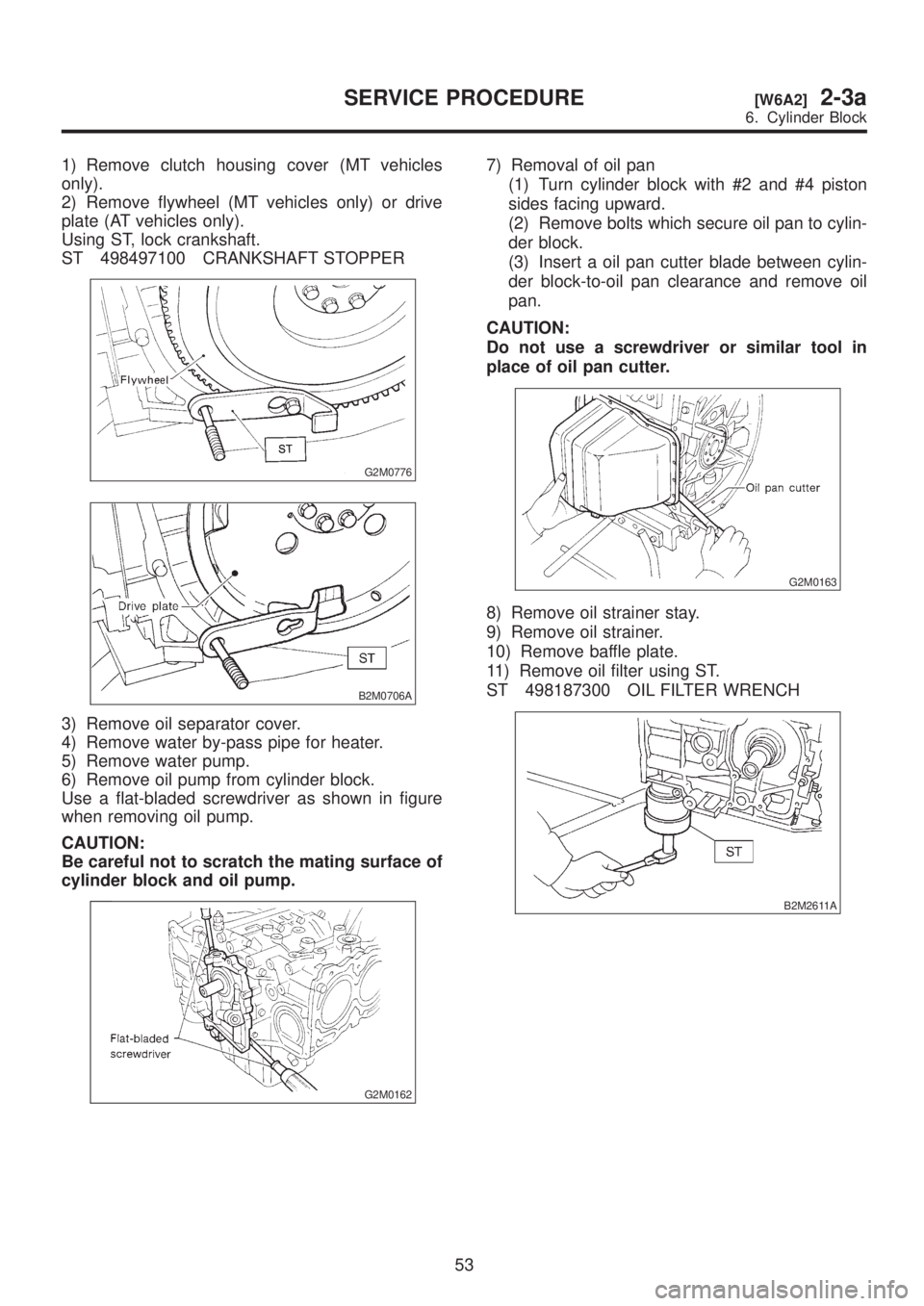
1) Remove clutch housing cover (MT vehicles
only).
2) Remove flywheel (MT vehicles only) or drive
plate (AT vehicles only).
Using ST, lock crankshaft.
ST 498497100 CRANKSHAFT STOPPER
G2M0776
B2M0706A
3) Remove oil separator cover.
4) Remove water by-pass pipe for heater.
5) Remove water pump.
6) Remove oil pump from cylinder block.
Use a flat-bladed screwdriver as shown in figure
when removing oil pump.
CAUTION:
Be careful not to scratch the mating surface of
cylinder block and oil pump.
G2M0162
7) Removal of oil pan
(1) Turn cylinder block with #2 and #4 piston
sides facing upward.
(2) Remove bolts which secure oil pan to cylin-
der block.
(3) Insert a oil pan cutter blade between cylin-
der block-to-oil pan clearance and remove oil
pan.
CAUTION:
Do not use a screwdriver or similar tool in
place of oil pan cutter.
G2M0163
8) Remove oil strainer stay.
9) Remove oil strainer.
10) Remove baffle plate.
11) Remove oil filter using ST.
ST 498187300 OIL FILTER WRENCH
B2M2611A
53
[W6A2]2-3aSERVICE PROCEDURE
6. Cylinder Block
Page 124 of 1456
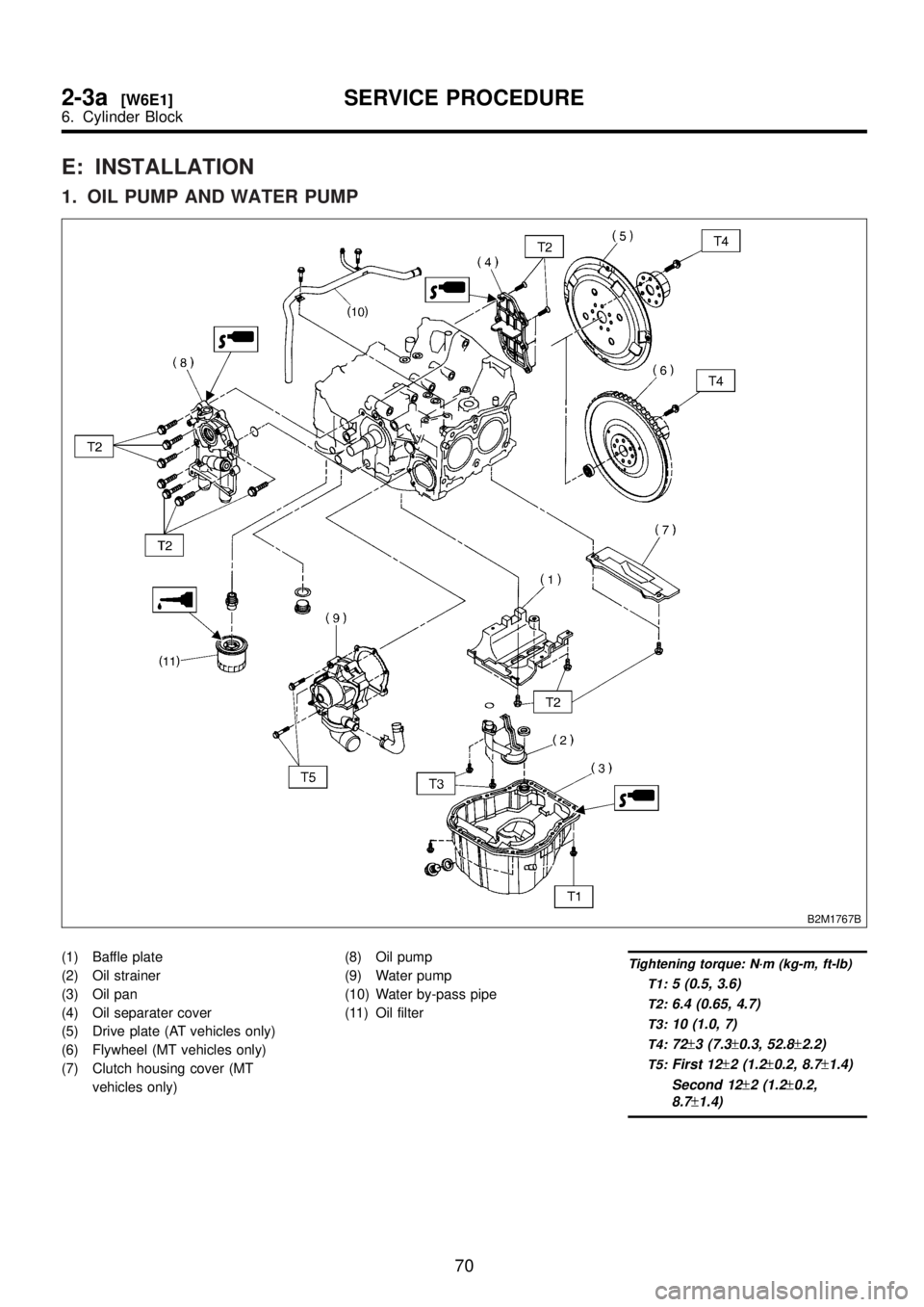
E: INSTALLATION
1. OIL PUMP AND WATER PUMP
B2M1767B
(1) Baffle plate
(2) Oil strainer
(3) Oil pan
(4) Oil separater cover
(5) Drive plate (AT vehicles only)
(6) Flywheel (MT vehicles only)
(7) Clutch housing cover (MT
vehicles only)(8) Oil pump
(9) Water pump
(10) Water by-pass pipe
(11) Oil filterTightening torque: N´m (kg-m, ft-lb)
T1:
5 (0.5, 3.6)
T2:6.4 (0.65, 4.7)
T3:10 (1.0, 7)
T4:72±3 (7.3±0.3, 52.8±2.2)
T5:First 12±2 (1.2±0.2, 8.7±1.4)
Second 12
±2 (1.2±0.2,
8.7
±1.4)
70
2-3a[W6E1]SERVICE PROCEDURE
6. Cylinder Block
Page 126 of 1456

(2) Apply fluid packing to matching surface of
oil pump.
Fluid packing:
THREE BOND 1215 or equivalent
S2M0739A
(3) Apply a coat of engine oil to the inside of the
oil seal.
S2M0118A
(4) Install oil pump on cylinder block. Be care-
ful not to damage oil seal during installation.
CAUTION:
IDo not forget to install O-ring and seal when
installing oil pump.
IAlign flat surface of oil pump's inner rotor
with crankshaft before installation.
9) Install water pump and gasket.
CAUTION:
IBe sure to use a new gasket.
IWhen installing water pump, tighten bolts in
two stages in alphabetical sequence as shown
in figure.
H2M1568B
10) Install water by-pass pipe for heater.
11) Install oil filter using ST.
ST 498187300 OIL FILTER WRENCH
B2M2611A
2. RELATED PARTS
1) Install cylinder head, valve rocker assembly
and rocker cover.
2) Install timing belt and camshaft sprocket.
3) Install water pipe.
4) Install intake manifold.
72
2-3a[W6E2]SERVICE PROCEDURE
6. Cylinder Block
Page 142 of 1456
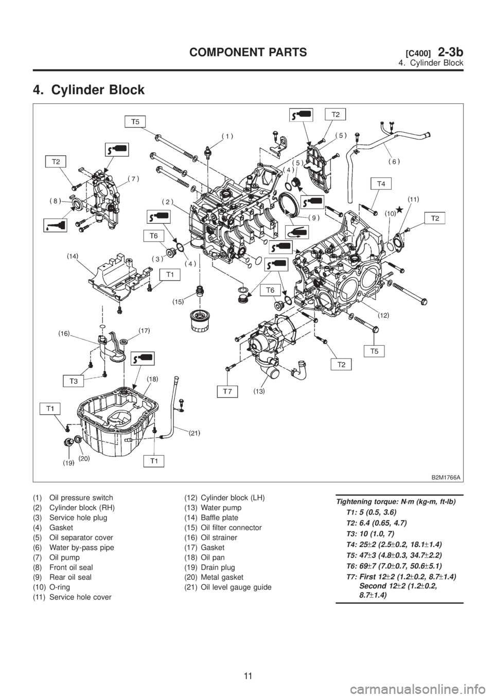
4. Cylinder Block
B2M1766A
(1) Oil pressure switch
(2) Cylinder block (RH)
(3) Service hole plug
(4) Gasket
(5) Oil separator cover
(6) Water by-pass pipe
(7) Oil pump
(8) Front oil seal
(9) Rear oil seal
(10) O-ring
(11) Service hole cover(12) Cylinder block (LH)
(13) Water pump
(14) Baffle plate
(15) Oil filter connector
(16) Oil strainer
(17) Gasket
(18) Oil pan
(19) Drain plug
(20) Metal gasket
(21) Oil level gauge guideTightening torque: N´m (kg-m, ft-lb)
T1:
5 (0.5, 3.6)
T2:6.4 (0.65, 4.7)
T3:10 (1.0, 7)
T4:25±2 (2.5±0.2, 18.1±1.4)
T5:47±3 (4.8±0.3, 34.7±2.2)
T6:69±7 (7.0±0.7, 50.6±5.1)
T7:First 12±2 (1.2±0.2, 8.7±1.4)
Second 12
±2 (1.2±0.2,
8.7
±1.4)
11
[C400]2-3bCOMPONENT PARTS
4. Cylinder Block
Page 182 of 1456
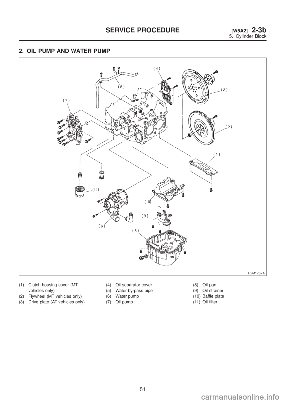
2. OIL PUMP AND WATER PUMP
B2M1767A
(1) Clutch housing cover (MT
vehicles only)
(2) Flywheel (MT vehicles only)
(3) Drive plate (AT vehicles only)(4) Oil separator cover
(5) Water by-pass pipe
(6) Water pump
(7) Oil pump(8) Oil pan
(9) Oil strainer
(10) Baffle plate
(11) Oil filter
51
[W5A2]2-3bSERVICE PROCEDURE
5. Cylinder Block
Page 183 of 1456
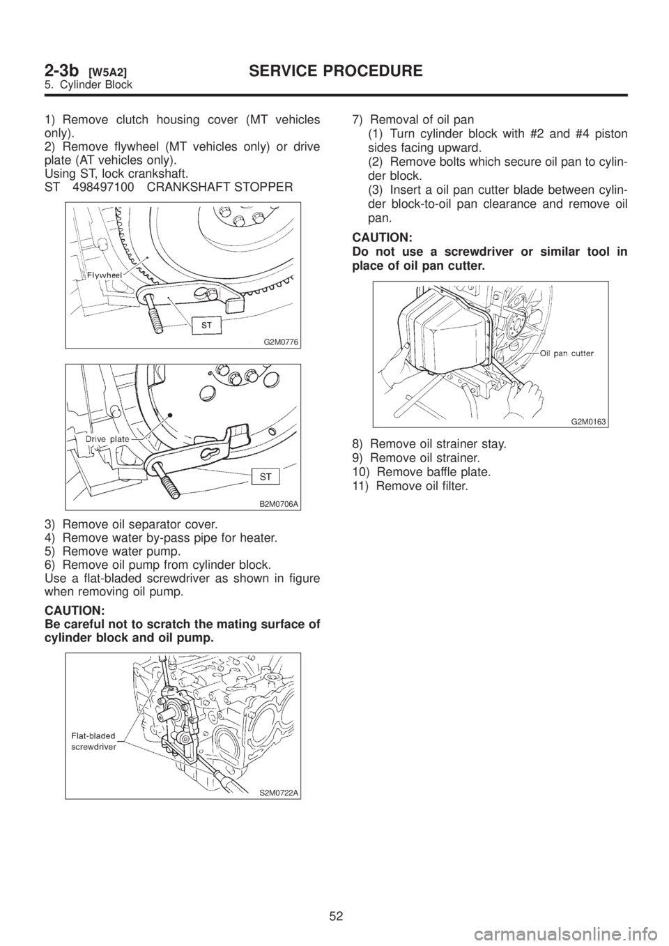
1) Remove clutch housing cover (MT vehicles
only).
2) Remove flywheel (MT vehicles only) or drive
plate (AT vehicles only).
Using ST, lock crankshaft.
ST 498497100 CRANKSHAFT STOPPER
G2M0776
B2M0706A
3) Remove oil separator cover.
4) Remove water by-pass pipe for heater.
5) Remove water pump.
6) Remove oil pump from cylinder block.
Use a flat-bladed screwdriver as shown in figure
when removing oil pump.
CAUTION:
Be careful not to scratch the mating surface of
cylinder block and oil pump.
S2M0722A
7) Removal of oil pan
(1) Turn cylinder block with #2 and #4 piston
sides facing upward.
(2) Remove bolts which secure oil pan to cylin-
der block.
(3) Insert a oil pan cutter blade between cylin-
der block-to-oil pan clearance and remove oil
pan.
CAUTION:
Do not use a screwdriver or similar tool in
place of oil pan cutter.
G2M0163
8) Remove oil strainer stay.
9) Remove oil strainer.
10) Remove baffle plate.
11) Remove oil filter.
52
2-3b[W5A2]SERVICE PROCEDURE
5. Cylinder Block
Page 199 of 1456
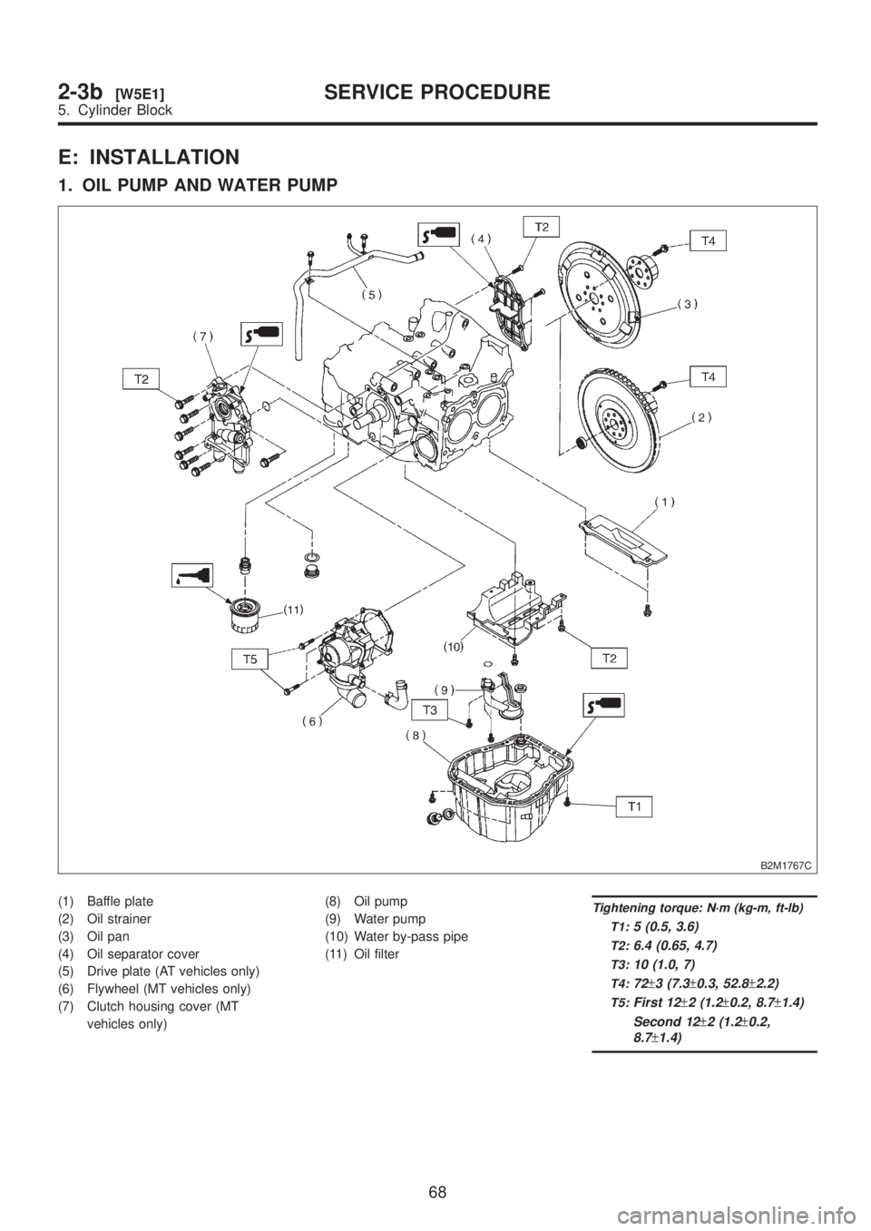
E: INSTALLATION
1. OIL PUMP AND WATER PUMP
B2M1767C
(1) Baffle plate
(2) Oil strainer
(3) Oil pan
(4) Oil separator cover
(5) Drive plate (AT vehicles only)
(6) Flywheel (MT vehicles only)
(7) Clutch housing cover (MT
vehicles only)(8) Oil pump
(9) Water pump
(10) Water by-pass pipe
(11) Oil filterTightening torque: N´m (kg-m, ft-lb)
T1:
5 (0.5, 3.6)
T2:6.4 (0.65, 4.7)
T3:10 (1.0, 7)
T4:72±3 (7.3±0.3, 52.8±2.2)
T5:First 12±2 (1.2±0.2, 8.7±1.4)
Second 12
±2 (1.2±0.2,
8.7
±1.4)
68
2-3b[W5E1]SERVICE PROCEDURE
5. Cylinder Block
Page 201 of 1456
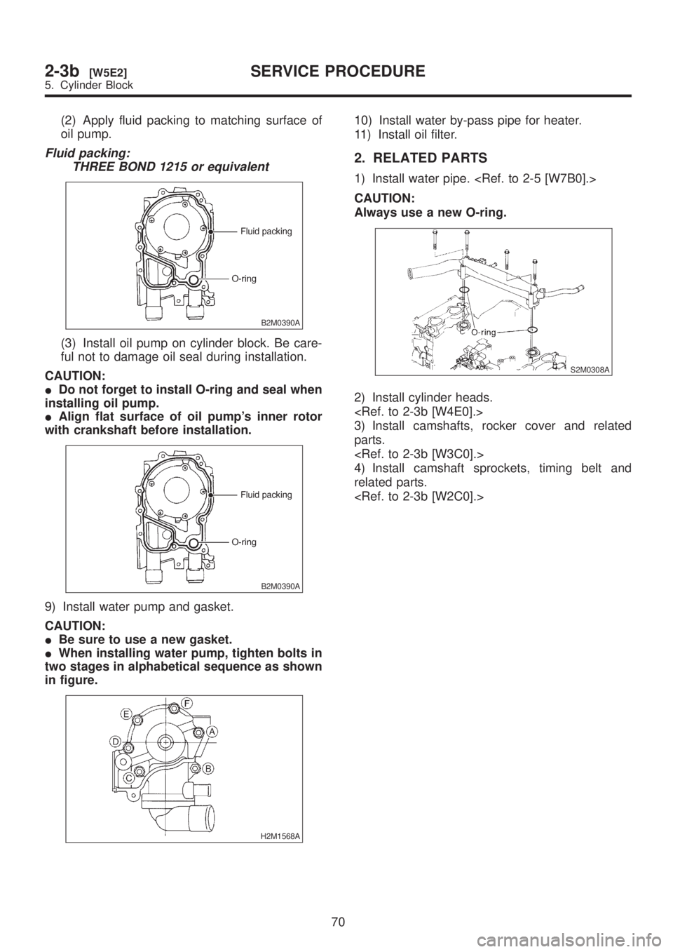
(2) Apply fluid packing to matching surface of
oil pump.
Fluid packing:
THREE BOND 1215 or equivalent
B2M0390A
(3) Install oil pump on cylinder block. Be care-
ful not to damage oil seal during installation.
CAUTION:
IDo not forget to install O-ring and seal when
installing oil pump.
IAlign flat surface of oil pump's inner rotor
with crankshaft before installation.
B2M0390A
9) Install water pump and gasket.
CAUTION:
IBe sure to use a new gasket.
IWhen installing water pump, tighten bolts in
two stages in alphabetical sequence as shown
in figure.
H2M1568A
10) Install water by-pass pipe for heater.
11) Install oil filter.
2. RELATED PARTS
1) Install water pipe.
CAUTION:
Always use a new O-ring.
S2M0308A
2) Install cylinder heads.
3) Install camshafts, rocker cover and related
parts.
4) Install camshaft sprockets, timing belt and
related parts.
70
2-3b[W5E2]SERVICE PROCEDURE
5. Cylinder Block