climate control SUBARU LEGACY 2010 5.G Owners Manual
[x] Cancel search | Manufacturer: SUBARU, Model Year: 2010, Model line: LEGACY, Model: SUBARU LEGACY 2010 5.GPages: 448, PDF Size: 7.36 MB
Page 3 of 448

Warranties &Warranties for U.S.A.
All SUBARU vehicles distributed by
Subaru of America, Inc. and sold at retail
by an authorized SUBARU dealer in the
United States come with the followingwarranties: . SUBARU Limited Warranty
. Emission Control Systems Warranty
. Emissions Performance Warranty
All warranty information, including details
of coverage and exclusions, is in the“ Warranty and Maintenance Booklet ”.
Please read these warranties carefully. & Warranties for Canada
All SUBARU vehicles distributed by
Subaru Canada, Inc. and sold at retail by
an authorized SUBARU dealer in Canada
come with the following warranties: . SUBARU Limited Warranty
. Anti-Corrosion Warranty
. Emission Control Warranty
All warranty information, including details
of coverage and exclusions, is in the“ Warranty and Service Booklet ”. Please
read these warranties carefully. How to use this Owner
’s
Manual
& Using your Owner ’s Manual
Before you operate your vehicle, carefully
read this manual. To protect yourself and
extend the service life of your vehicle,
follow the instructions in this manual.
Failure to observe these instructions may
result in serious injury and damage to yourvehicle.
This manual is composed of fourteen
chapters. Each chapter begins with a brief
table of contents, so you can usually tell at
a glance if that chapter contains the
information you want.
Chapter 1: Seat, seatbelt and SRS airbags
This chapter informs you how to use the
seat and seatbelt and contains precau-
tions for the SRS airbags.
Chapter 2: Keys and doors
This chapter informs you how to operate
the keys, locks and windows.
Chapter 3: Instruments and controls
This chapter informs you about the opera-
tion of instrument panel indicators and
how to use the instruments and otherswitches. Chapter 4: Climate control
This chapter informs you how to operate
the climate control.
Chapter 5: Audio
This chapter informs you how to operate
your audio system.
Chapter 6: Interior equipment
This chapter informs you how to operate
interior equipment.
Chapter 7: Starting and operating
This chapter informs you how to start and
operate your SUBARU.
Chapter 8: Driving tips
This chapter informs you how to drive your
SUBARU in various conditions and ex-
plains some safety tips on driving.
Chapter 9: In case of emergency
This chapter informs you what to do if you
have a problem while driving, such as a
flat tire or engine overheating.
Chapter 10: Appearance care
This chapter informs you how to keep your
SUBARU looking good.
Chapter 11: Maintenance and service
This chapter informs you when you need
to take your SUBARU to the dealer for
scheduled maintenance and informs you
how to keep your SUBARU running
properly.1
– CONTINUED –
Page 11 of 448

Table of contents
Seat, seatbelt and SRS airbags1
Keys and doors2
Instruments and controls
Climate control4
Audio5
Interior equipment6
Starting and operating7
Driving tips8
In case of emergency9
Appearance care10
Maintenance and service11
Specifications12
Consumer information and Reporting safety defects13
Index14
3
Page 16 of 448

14
1) Shift lever (MT) (page 7-16)/Select lever(AT and CVT) (page 7-19)
2) Climate control (page 4-1)
3) Audio (page 5-1)
4) Navigation system (Refer to the Owner ’s
Manual supplement for the navigation system)
5) Multi function display (page 3-24)
6) Glove box (page 6-6)
7) Cup holder (page 6-8)
Page 22 of 448

20
Function settings
A SUBARU dealer can change the settings of the functions shown in the following table to meet your personal requirements. Contact
the nearest SUBARU dealer for details.Item Function Possible settings Default setting Page
Alarm system Alarm system Operation/Non-operation Operation 2-16 Monitoring start delay time (after closure
of doors) 0 second/30 seconds 30 seconds 2-17
Impact sensor operation (only models
with shock sensors (dealer option)) Operation/Non-operation Non-operation 2-19
Passive arming Operation/Non-operation Non-operation 2-18
Map light/Dome light/Cargo area light illumination ON/OFF OFF 2-16
Remote keyless entry sys-tem Hazard warning flasher Operation/Non-operation Operation 2-8
Audible signal Operation/Non-operation Operation 2-11
Key lock-in prevention Key lock-in prevention Operation/Non-operation Operation 2-7
Defogger and deicer system
for models with the automatic
climate control system Rear window defogger, outside mirror
defogger and windshield wiper deicer
Operation for 15 minutes/
Continuous operationOperation for 15 minutes 3-34
Map light/Dome light/Cargo
area light Operation of map light/Dome light/Cargo
area light OFF delay timer OFF/Short/Normal/Long Long 6-2
Battery drainage preventionfunction Battery drainage prevention function Operation/Non-operation Operation 2-6
Seatbelt warning Sounds a chime while driving Operation/Non-operation Operation 1-14
Auto on/off headlights Sensitivity of the operation of the auto on/ off headlights Low/Normal/High/Very high Normal 3-28
Page 153 of 448

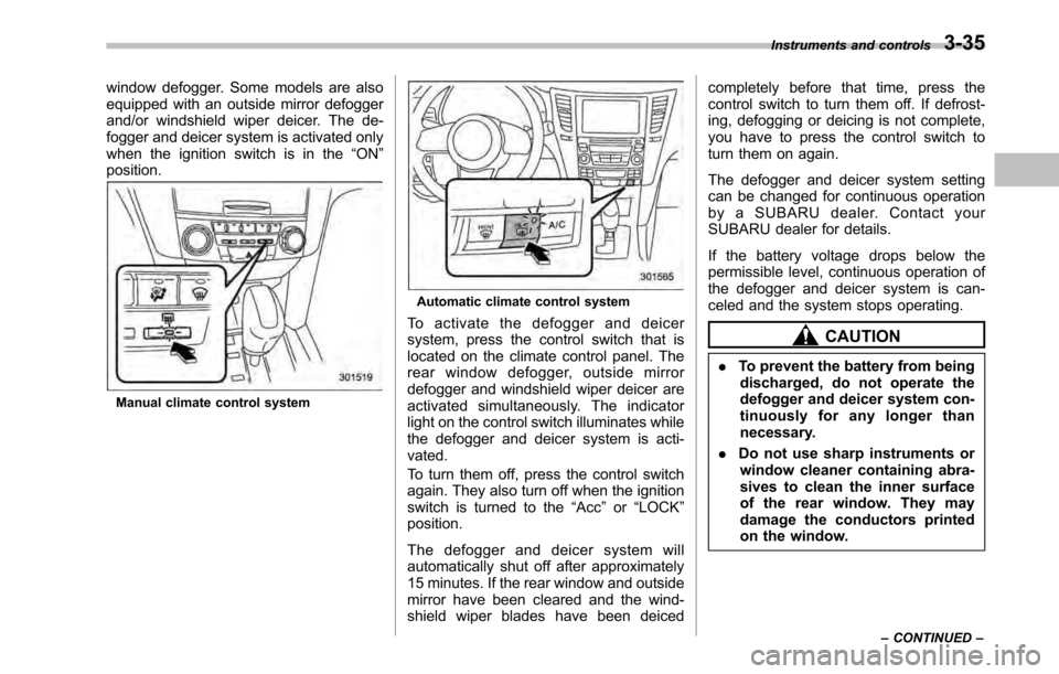
window defogger. Some models are also
equipped with an outside mirror defogger
and/or windshield wiper deicer. The de-
fogger and deicer system is activated only
when the ignition switch is in the“ON ”
position.
Manual climate control system
Automatic climate control system
To activate the defogger and deicer
system, press the control switch that is
located on the climate control panel. The
rear window defogger, outside mirror
defogger and windshield wiper deicer are
activated simultaneously. The indicator
light on the control switch illuminates while
the defogger and deicer system is acti-vated.
To turn them off, press the control switch
again. They also turn off when the ignition
switch is turned to the “Acc ”or “LOCK ”
position.
The defogger and deicer system will
automatically shut off after approximately
15 minutes. If the rear window and outside
mirror have been cleared and the wind-
shield wiper blades have been deiced completely before that time, press the
control switch to turn them off. If defrost-
ing, defogging or deicing is not complete,
you have to press the control switch to
turn them on again.
The defogger and deicer system setting
can be changed for continuous operation
by a SUBARU dealer. Contact your
SUBARU dealer for details.
If the battery voltage drops below the
permissible level, continuous operation of
the defogger and deicer system is can-
celed and the system stops operating.
CAUTION
. To prevent the battery from being
discharged, do not operate the
defogger and deicer system con-
tinuously for any longer than
necessary.
. Do not use sharp instruments or
window cleaner containing abra-
sives to clean the inner surface
of the rear window. They may
damage the conductors printed
on the window. Instruments and controls
3-35
– CONTINUED –
Page 159 of 448

Ventilator.............................................................. 4-2
Air flow selection ................................................ 4-2
Ventilators ........................................................... 4-3
Manual climate control system (if equipped) ..................................................... 4-4
Control panel ...................................................... 4-4
Heater operation ................................................. 4-6
Air conditioner operation ..................................... 4-7
Automatic climate control system (if equipped) ..................................................... 4-8
Control panel ...................................................... 4-9
Temperature sensors .......................................... 4-13
Operating tips for heater and air conditioner ....................................................... 4-14
Cleaning ventilator grille ..................................... 4-14 Efficient cooling after parking in direct
sunlight ........................................................... 4-14
Lubrication oil circulation in the refrigerant circuit .............................................................. 4-14
Checking air conditioning system before summer season ............................................................ 4-14
Cooling and dehumidifying in high humidity and low temperature weather condition ................... 4-14
Air conditioner compressor shut-off when engine is heavily loaded .............................................. 4-14
Refrigerant for your climate control system ... ..... 4-14
Air filtration system ........................................... 4-15
Replacing an air filter ......................................... 4-15Climate control
4
Page 160 of 448

4-2Climate control
Ventilator &Air flow selection
Page 161 of 448

&Ventilators
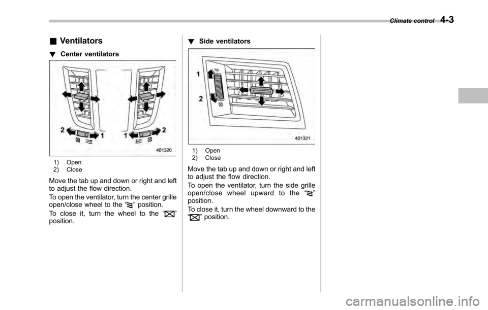
! Center ventilators
1) Open
2) Close
Move the tab up and down or right and left
to adjust the flow direction.
To open the ventilator, turn the center grille
open/close wheel to the “
”position.
To close it, turn the wheel to the “
”
position. !
Side ventilators
1) Open
2) Close
Move the tab up and down or right and left
to adjust the flow direction.
To open the ventilator, turn the side grille
open/close wheel upward to the “
”
position.
To close it, turn the wheel downward to the “
” position. Climate control
4-3
Page 162 of 448

4-4Climate control
Manual climate control system (if equipped) &Control panel1) Fan speed control dial
2) Temperature control dial
3) Air flow control buttons
4) Air conditioner button
5) Air inlet selection button
6) Rear window defogger button (Refer to
“Defogger and deicer ”F 3-34.)
Page 163 of 448

!Fan speed control dial
The fan operates only when the ignition
switch is turned to the “ON ”position. The
fan speed control dial is used to select
four fan speeds. ! Temperature control dial
This dial regulates the temperature of air
flow from the air outlets over a range from
the blue side (cool) to red side (warm). !Air flow control buttons
The air flow control buttons consist of the
following five buttons:
: Air flows through the instrument panel
outlets.
: Air flows through the instrument panel
outlets and the foot outlets.
: Air flows through the instrument panel
outlets, the foot outlets, and some through
the windshield defroster outlets.
: Air flows through the instrument panel
outlets, the windshield defroster outlets,
and the foot outlets.
: Air flows through the instrument panel
outlets and the windshield defroster out- lets.
NOTE
When the “
”button or “”button is
pressed the air conditioner compres-
sor automatically operates to quickly
defog the windshield. However the
indicator on the air conditioner button
will not illuminate. At the same time,
the air inlet selection is automatically
set to “outside air ”mode.
Climate control
4-5
– CONTINUED –