automatic transmission SUBARU LEGACY 2012 5.G Owners Manual
[x] Cancel search | Manufacturer: SUBARU, Model Year: 2012, Model line: LEGACY, Model: SUBARU LEGACY 2012 5.GPages: 474, PDF Size: 17.45 MB
Page 5 of 474
2
Chapter 12: Specifications
This chapter informs you about the dimen-
sions and capacities of your SUBARU.
Chapter 13: Consumer information and
Reporting safety defects
This chapter informs you about Tire
information, Uniform tire quality grading
standards and Reporting safety defects.
Chapter 14: Index
This is an alphabetical listing of all that’sin
this manual. You can use it to quickly find
something you want to read. & Safety warnings
You will find a number of WARNINGs,
CAUTIONs and NOTEs in this manual.
These safety warnings alert you to poten-
tial hazards that could result in injury to
you or others.
Please read these safety warnings as well
as all other portions of this manual care-
fully in order to gain a better understand-
ing of how to use your SUBARU vehicle
safely.
WARNING
A WARNING indicates a situation in
which serious injury or death could
result if the warning is ignored.
CAUTION
A CAUTION indicates a situation in
which injury or damage to your
vehicle, or both, could result if the
caution is ignored.
NOTE
A NOTE gives information or sugges-
tions how to make better use of yourvehicle. & Safety symbol
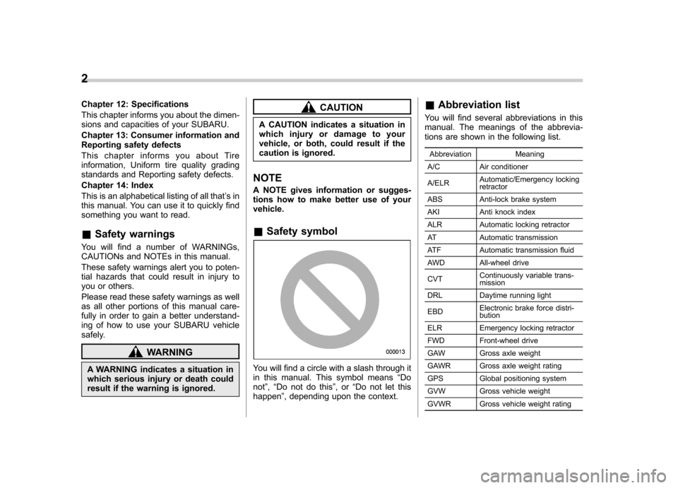
You will find a circle with a slash through it
in this manual. This symbol means “Do
not ”, “Do not do this ”,or “Do not let this
happen ”, depending upon the context. &
Abbreviation list
You will find several abbreviations in this
manual. The meanings of the abbrevia-
tions are shown in the following list.
Abbreviation Meaning
A/C Air conditioner A/ELR Automatic/Emergency locking retractor
ABS Anti-lock brake system
AKI Anti knock index
ALR Automatic locking retractor
AT Automatic transmission
ATF Automatic transmission fluid
AWD All-wheel drive CVT Continuously variable trans- mission
DRL Daytime running light EBD Electronic brake force distri- bution
ELR Emergency locking retractor
FWD Front-wheel drive
GAW Gross axle weight
GAWR Gross axle weight rating
GPS Global positioning system
GVW Gross vehicle weight
GVWR Gross vehicle weight rating
Page 6 of 474
Abbreviation Meaning
HID High intensity discharge
INT Intermittent
LATCH Lower anchors and tethers for children
LED Light emitting diode
LSD Limited slip differential
MIL Malfunction indicator light MMT Methylcyclopentadienyl man-
ganese tricarbonyl
MT Manual transmission
OBD On-board diagnostics
RON Research octane number
SI-DRIVE SUBARU Intelligent Drive SRS Supplemental restraint sys- tem
TIN Tire identification number TPMS Tire pressure monitoring sys- tem
VDC Vehicle dynamics control Vehicle symbols
There are some of the symbols you may
see on your vehicle.
For warning and indicator lights, refer to “
Warning and indicator lights ”F 19.
Mark Name
WARNING
CAUTION
Power door lock
Power door unlock
Power window with automatic
open and close function
Passengers ’windows lock
Fuel
Front fog lights
Hazard warning flasher Mark Name
Seat heater
Child restraint lower an-
chorages
Child restraint top tether an-
chorages
Horn
Windshield wiper
Windshield washer
Rear window wiper
Rear window washer
Lights
Tail lights, license plate light
and instrument panel illumi-nation
Headlights3
– CONTINUED –
Page 155 of 474
3-36Instruments and controls
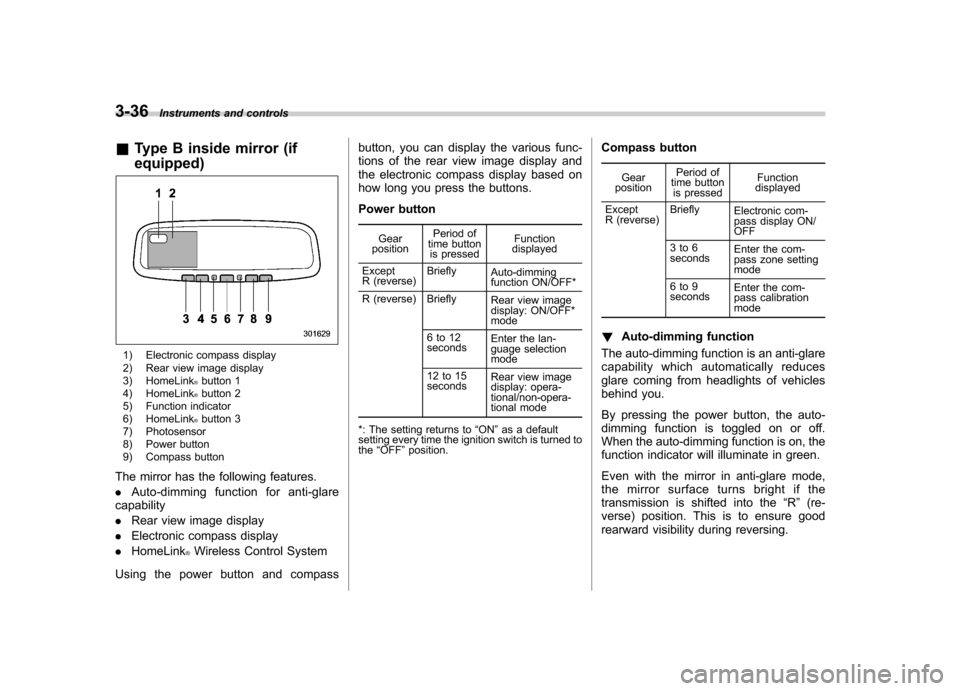
&Type B inside mirror (if equipped)
1) Electronic compass display
2) Rear view image display
3) HomeLink
®button 1
4) HomeLink®button 2
5) Function indicator
6) HomeLink
®button 3
7) Photosensor
8) Power button
9) Compass button
The mirror has the following features. . Auto-dimming function for anti-glare
capability. Rear view image display
. Electronic compass display
. HomeLink
®Wireless Control System
Using the power button and compass button, you can display the various func-
tions of the rear view image display and
the electronic compass display based on
how long you press the buttons.
Power button
Gear
position Period of
time button
is pressed Function
displayed
Except
R (reverse) Briefly
Auto-dimming
function ON/OFF*
R (reverse) Briefly Rear view image
display: ON/OFF* mode
6to12 seconds Enter the lan-
guage selection mode
12 to 15 seconds Rear view image
display: opera-
tional/non-opera-
tional mode
*: The setting returns to “ON ”as a default
setting every time the ignition switch is turned to the “OFF ”position. Compass button
Gear
position Period of
time button is pressed Function
displayed
Except
R (reverse) Briefly
Electronic com-
pass display ON/ OFF
3to6
seconds Enter the com-
pass zone setting mode
6to9
seconds Enter the com-
pass calibration mode
! Auto-dimming function
The auto-dimming function is an anti-glare
capability which automatically reduces
glare coming from headlights of vehicles
behind you.
By pressing the power button, the auto-
dimming function is toggled on or off.
When the auto-dimming function is on, the
function indicator will illuminate in green.
Even with the mirror in anti-glare mode,
the mirror surface turns bright if the
transmission is shifted into the “R ” (re-
verse) position. This is to ensure good
rearward visibility during reversing.
Page 156 of 474
The mirror has a photosensor attached on
both the front and back sides. During
nighttime driving, these sensors detect
distracting glare from vehicle headlights
behind you and automatically dim the
mirror to eliminate glare and preserve
your vision. For this reason, use care not
to cover the sensors with stickers, or other
similar items. Periodically wipe the sen-
sors clean using a piece of dry soft cotton
cloth or an applicator. NOTE
When cleaning the mirror, use a paper
towel or similar item dampened with
glass cleaner. Do not spray glass
cleaner directly on the mirror surface.
By doing so, the sprayed glass cleaner
could enter the inside of the mirrorhousing. That may cause a malfunction
in the mirror. !
Rear view image display
When the ignition switch is in the “ON ”
position and the transmission is in the “R ”
(reverse) position, the rear view camera
automatically displays the rear view image
behind the vehicle on the inside mirror.
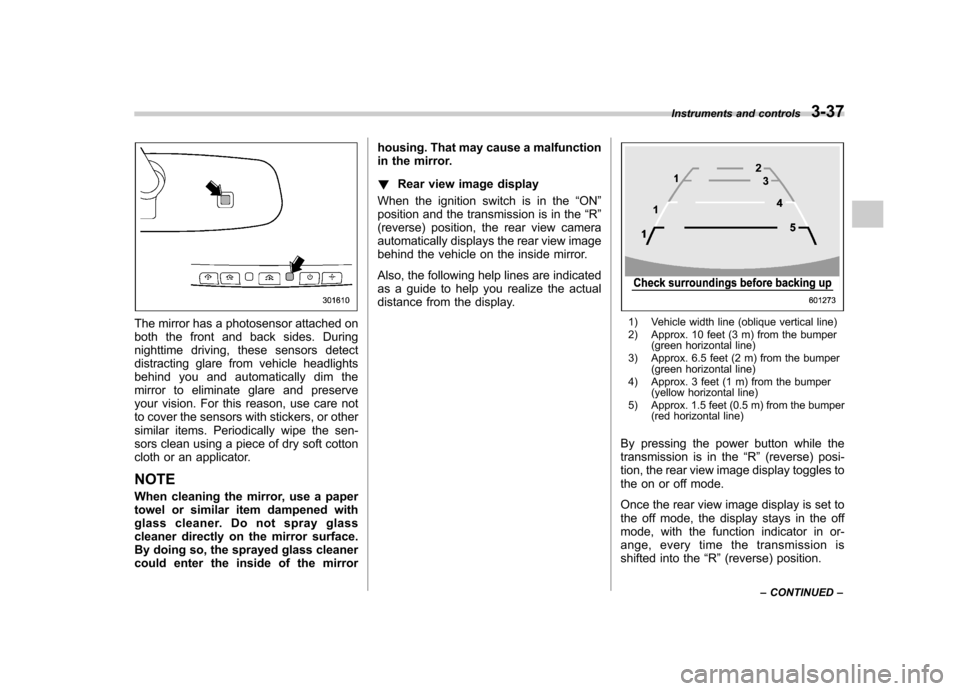
Also, the following help lines are indicated
as a guide to help you realize the actual
distance from the display.1) Vehicle width line (oblique vertical line)
2) Approx. 10 feet (3 m) from the bumper (green horizontal line)
3) Approx. 6.5 feet (2 m) from the bumper (green horizontal line)
4) Approx. 3 feet (1 m) from the bumper (yellow horizontal line)
5) Approx. 1.5 feet (0.5 m) from the bumper (red horizontal line)
By pressing the power button while the
transmission is in the “R ” (reverse) posi-
tion, the rear view image display toggles to
the on or off mode.
Once the rear view image display is set to
the off mode, the display stays in the off
mode, with the function indicator in or-
ange, every time the transmission is
shifted into the “R ”(reverse) position.
Instruments and controls
3-37
– CONTINUED –
Page 162 of 474
begins to flash slowly (after approximately
20 seconds), position the hand-held trans-
mitter of the device between 1 to 3 inches
(25 to 76 mm) away from the HomeLink
®button you wish to program.
3. Press and hold the hand-held trans-
mitter button. The HomeLink
®indicator
light will flash, first slowly and then rapidly.
4. When the indicator light begins to flash
rapidly, release both buttons.
The programming for the previous device
is now erased and the new device can be
operated by pressing the HomeLink
®button. ! Erasing HomeLink
®button memory
NOTE . Performing this procedure erases
the memory of all the preprogrammed
buttons simultaneously. The memory
of individual buttons cannot be erased.. It is recommended that upon the
sale of the vehicle, the memory of all
programmed HomeLink
®buttons be
erased for security purposes.
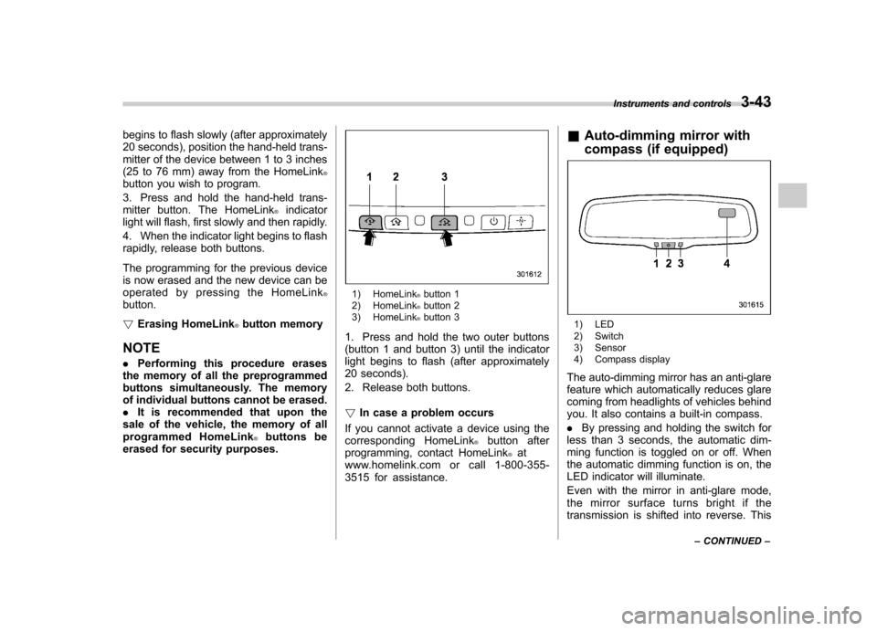
1) HomeLink®button 1
2) HomeLink®button 2
3) HomeLink®button 3
1. Press and hold the two outer buttons
(button 1 and button 3) until the indicator
light begins to flash (after approximately
20 seconds).
2. Release both buttons. ! In case a problem occurs
If you cannot activate a device using the
corresponding HomeLink
®button after
programming, contact HomeLink®at
www.homelink.com or call 1-800-355-
3515 for assistance. &
Auto-dimming mirror with
compass (if equipped)
1) LED
2) Switch
3) Sensor
4) Compass display
The auto-dimming mirror has an anti-glare
feature which automatically reduces glare
coming from headlights of vehicles behind
you. It also contains a built-in compass. . By pressing and holding the switch for
less than 3 seconds, the automatic dim-
ming function is toggled on or off. When
the automatic dimming function is on, the
LED indicator will illuminate.
Even with the mirror in anti-glare mode,
the mirror surface turns bright if the
transmission is shifted into reverse. This Instruments and controls
3-43
– CONTINUED –
Page 164 of 474
&Auto-dimming mirror with
compass and HomeLink
®(if
equipped)
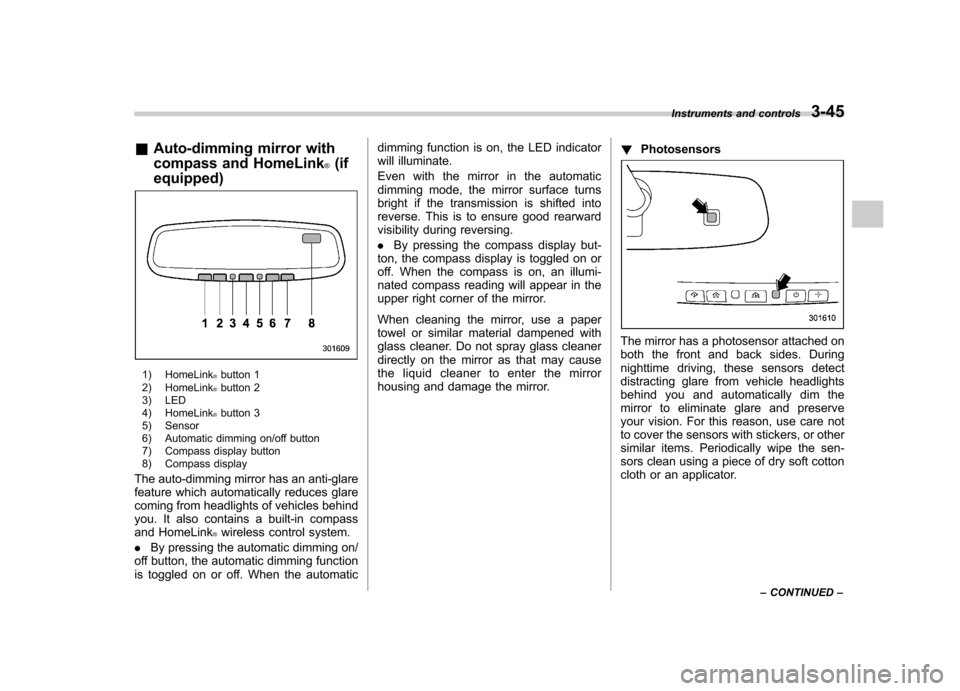
1) HomeLink®button 1
2) HomeLink®button 2
3) LED
4) HomeLink
®button 3
5) Sensor
6) Automatic dimming on/off button
7) Compass display button
8) Compass display
The auto-dimming mirror has an anti-glare
feature which automatically reduces glare
coming from headlights of vehicles behind
you. It also contains a built-in compass
and HomeLink
®wireless control system.
. By pressing the automatic dimming on/
off button, the automatic dimming function
is toggled on or off. When the automatic dimming function is on, the LED indicator
will illuminate.
Even with the mirror in the automatic
dimming mode, the mirror surface turns
bright if the transmission is shifted into
reverse. This is to ensure good rearward
visibility during reversing. .
By pressing the compass display but-
ton, the compass display is toggled on or
off. When the compass is on, an illumi-
nated compass reading will appear in the
upper right corner of the mirror.
When cleaning the mirror, use a paper
towel or similar material dampened with
glass cleaner. Do not spray glass cleaner
directly on the mirror as that may cause
the liquid cleaner to enter the mirror
housing and damage the mirror. !
Photosensors
The mirror has a photosensor attached on
both the front and back sides. During
nighttime driving, these sensors detect
distracting glare from vehicle headlights
behind you and automatically dim the
mirror to eliminate glare and preserve
your vision. For this reason, use care not
to cover the sensors with stickers, or other
similar items. Periodically wipe the sen-
sors clean using a piece of dry soft cotton
cloth or an applicator. Instruments and controls
3-45
– CONTINUED –
Page 278 of 474

Fuel...................................................................... 7-2
Fuel requirements ............................................... 7-2
Fuel filler lid and cap ........................................... 7-3
State emission testing (U.S. only) ...................... 7-6
Preparing to drive ............................................... 7-7
Starting the engine .............................................. 7-8
MT models .......................................................... 7-8
AT and CVT models ............................................. 7-9
Stopping the engine ........................................... 7-10
Remote engine start system (dealer option) .............................................................. 7-10
Starting your vehicle .......................................... 7-10
Remote start safety features ............................... 7-11
Entering the vehicle while it is running via remote start ................................................................. 7-11
Remote start confirmation transmitter feature ............................................................. 7-12
Entering the vehicle following remote engine start shutdown ......................................................... 7-13
Pre-heating or pre-cooling the interior of the vehicle ............................................................. 7-13
Service mode ..................................................... 7-13
Remote transmitter program ............................... 7-13
System maintenance .......................................... 7-14
Manual transmission .......................................... 7-15
Selecting reverse gear ........................................ 7-16
Shifting speeds .................................................. 7-16
Driving tips ........................................................ 7-17
Automatic transmission/Continuously variable transmission ..................................... 7-17
Select lever ........................................................ 7-18 Shift lock function
............................................. 7-20
Selection of manual mode .................................. 7-21
Driving tips ........................................................ 7-22
Power steering ................................................... 7-23
Braking ............................................................... 7-23
Braking tips ....................................................... 7-23
Brake system .................................................... 7-23
Disc brake pad wear warning indicators ............. 7-24
ABS (Anti-lock Brake System) .......................... 7-24
ABS system self-check ...................................... 7-25
ABS warning light .............................................. 7-25
Electronic Brake Force Distribution (EBD) system ............................................................. 7-25
Steps to take if EBD system malfunctions ..... ..... 7-25
Vehicle Dynamics Control system .................... 7-26
Vehicle Dynamics Control system monitor..... ..... 7-28
Vehicle Dynamics Control OFF switch ................ 7-28
Tire pressure monitoring system (TPMS) (if equipped) .................................................... 7-29
Parking your vehicle ......................................... 7-30
Electronic parking brake .................................... 7-31
Parking tips ....................................................... 7-34
Cruise control .................................................... 7-35
To set cruise control .......................................... 7-35
To temporarily cancel the cruise control ............. 7-36
To turn off the cruise control .............................. 7-36
To change the cruising speed .. .......................... 7-37
Cruise control indicator light .............................. 7-38
Cruise control set indicator light ........................ 7-38
Starting and operating
7
Page 294 of 474
enter the red area if these speeds are exceeded.
With the exception of cases where sudden
acceleration is required, the vehicle
should not be driven with the tachometer’s
needle inside the red area. Failure to
observe this precaution can lead to
excessive engine wear and poor fuel
economy. mph (km/h)
Gear Legacy
Outback
Non-turbo
models Turbo
models
1st 32 (52) 35 (56) 32 (52)
2nd 57 (92) 62 (100) 57 (92)
NOTE
Never exceed posted speed limits. & Driving tips
Do not drive with your foot resting on the
clutch pedal and do not use the clutch to
hold your vehicle at a standstill on an
upgrade. Either of those actions may
cause clutch damage.
Do not drive with your hand resting on the
shift lever. This may cause wear on the
transmission components.
When it is necessary to reduce vehicle
speed due to slow traffic, turning corners, or driving up steep hills, downshift to a
lower gear before the engine starts to
labor.
On steep downgrades, downshift the
transmission to 5th, 4th, 3rd or 2nd gear
as necessary; this helps to maintain a safe
speed and to extend brake pad life.
In this way, the engine provides a braking
effect. Remember, if you
“ride ”(over use)
the brakes while descending a hill, they
may overheat and not work properly.
The engine may, on rare occasions, knock
when the vehicle rapidly accelerates or
rapidly pulls away from a standstill. This
phenomenon does not indicate a problem. Automatic transmission/Con-
tinuously variable transmis-sion
The automatic transmission is electroni-
cally controlled and provides 5 forward
speeds and 1 reverse speed. The con-
tinuously variable transmission is electro-
nically controlled and provides an infinite
number of forward speeds and 1 reversespeed.
Both the automatic transmission and
continuously variable transmission have
a manual mode.
WARNING
Do not shift from the “P ” or “N ”
position into the “D ” or “R ” position
while depressing the accelerator
pedal. This may cause the vehicle
to jump forward or backward.
CAUTION
. Shift into the “P ” or “R ” position
only after the vehicle is comple-
tely stopped. Shifting while the
vehicle is moving may cause
damage to the transmission.
. Do not race the engine for more Starting and operating
7-17
– CONTINUED –
Page 295 of 474
7-18Starting and operating
than 5 seconds in any position
except the “N ” or “P ” position
when the brake is applied or
when chocks are used in the
wheels. This may cause the
transmission fluid to overheat.
. Avoid shifting from one of the
forward driving positions into the“ R ” position or vice versa until
the vehicle has completely
stopped. Such shifting may
cause damage to the transmis-sion.
. When parking the vehicle, first
securely apply the parking brake
and then place the select lever inthe “P ” position. Avoid parking
for a long time with the select
lever in any other position as
doing so could result in a dead
battery.
NOTE . For AT models, when the engine
coolant temperature is still low, the
transmission will upshift to higher
engine speeds than when the coolant
temperature is sufficiently high in order
to shorten the warm-up time and
improve driveability. The gearshift tim-
ing will automatically shift to the nor- mal timing after the engine has warmedup..
Immediately after transmission fluid
is replaced, you may feel that the
transmission operation is somewhat
unusual. This results from invalidation
of data which the on-board computer
has collected and stored in memory to
allow the transmission to shift at the
most appropriate times for the current
condition of your vehicle. Optimized
shifting will be restored as the vehicle
continues to be driven for a while.. When driving a vehicle that is
equipped with CVT under continuous
heavy load conditions such as towing a
camper or climbing a long, steep hill,
the engine speed or the vehicle speed
may automatically be reduced. This is
not a malfunction. This phenomenon
results from the engine control func-
tion maintaining the cooling perfor-
mance of the vehicle. The engine and
vehicle speed will return to a normal
speed when the engine is able to
maintain the optimum cooling perfor-
mance after the heavy load decreases.
Driving under a heavy load must be
performed with extreme care. Do not
try to pass a vehicle in front when
driving on an uphill slope while towing.. The continuously variable transmis-
sion is a chain type system that provides superior transmission effi-
ciency for maximum fuel economy. At
times, depending on varying driving
conditions, a chain operating sound
may be heard that is characteristic of
this type of system.
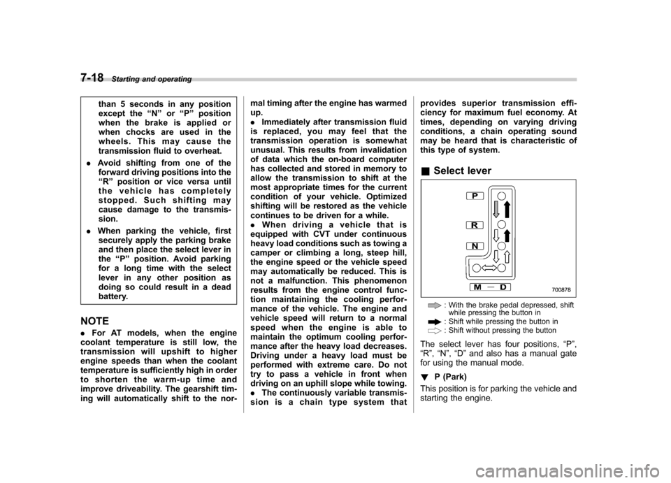
& Select lever
: With the brake pedal depressed, shift
while pressing the button in
: Shift while pressing the button in: Shift without pressing the button
The select lever has four positions, “P ”,
“ R ”, “N ”, “D ”and also has a manual gate
for using the manual mode. ! P (Park)
This position is for parking the vehicle and
starting the engine.
Page 296 of 474
In this position, the transmission is me-
chanically locked to prevent the vehicle
from rolling freely.
When you park the vehicle, first apply the
parking brake, then shift into the“P ”
position. Do not hold the vehicle with only
the transmission.
To shift the select lever from the “P ”to any
other position, you should depress the
brake pedal fully then move the select
lever. This prevents the vehicle from
lurching when it is started. NOTE
To protect the engine while the “P ”
position is selected, the engine is
controlled such that the engine speed
may not become too high even if the
accelerator pedal is depressed hard. ! R (Reverse)
This position is for backing the vehicle.
To shift from the “N ” to “R ”position, stop
the vehicle completely then move the
lever to the “R ”position.
! N (Neutral)
This position is for restarting a stalledengine.
In this position the wheels and transmis-
sion are not locked. In this position, the transmission is neutral; the vehicle will roll
freely, even on the slightest incline unless
the parking brake or foot brake is applied.
Avoid coasting with the transmission neutral.
During coasting, there is no engine brak-
ing effect.
NOTE . To protect the engine while the “N ”
position is selected, the engine is
controlled such that the engine speed
may not become too high even if the
accelerator pedal is depressed hard.. If the select lever is in the “N ”
position when you stop the engine for
parking, you may not subsequently be
able to move it to the “R ” and “P ”
positions. If this happens, turn the
ignition switch to the “ON ”position.
You will then be able to move the select
lever to the “P ” position.
WARNING
Do not drive the vehicle with the
select lever in the “N ” (neutral)
position. Engine braking has no
effect in this condition and the risk
of an accident is consequently in-creased. !
D (Drive)
This position is for normal driving. The
transmission automatically shifts into a
suitable gear according to the vehicle
speed and the acceleration you require.
When more acceleration is required in this
position, depress the accelerator pedal
fully to the floor and hold that position. The
transmission will automatically downshift.
When you release the pedal, the transmis-
sion will return to the original gear posi-tion.
To use the manual mode, move the lever
from this position into the manual gate.
NOTE (AT models only)
Automatic downshifts to 4th or 3rd may
occur even when driving on a level
road depending on conditions, such as
how hard you depress the brake pedal. ! While climbing a grade
When driving up a hill, undesired upshift is
prevented from taking place when the
accelerator is released. This minimizes
the chance of subsequent downshifting to
a lower gear when accelerating again.
This prevents repeated upshifting and
downshifting resulting in a smoother op-
eration of the vehicle. Starting and operating
7-19
– CONTINUED –