tow SUBARU LEGACY 2016 6.G Owners Manual
[x] Cancel search | Manufacturer: SUBARU, Model Year: 2016, Model line: LEGACY, Model: SUBARU LEGACY 2016 6.GPages: 572
Page 14 of 572
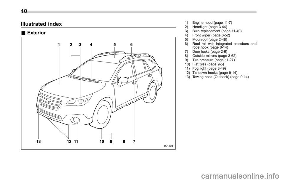
Illustrated index
&Exterior
1) Engine hood (page 11-7)
2) Headlight (page 3-44)
3) Bulb replacement (page 11-40)
4) Front wiper (page 3-52)
5) Moonroof (page 2-48)
6) Roof rail with integrated crossbars and
rope hook (page 8-14)
7) Door locks (page 2-6)
8) Outside mirrors (page 3-62)
9) Tire pressure (page 11-27)
10) Flat tires (page 9-5)
11) Fog light (page 3-49)
12) Tie-down hooks (page 9-14)
13) Towing hook (Outback) (page 9-14)
10
Page 15 of 572

1) Rear window defogger (page 3-54)
2) Fuel filler lid and cap (page 7-4)
3) Child safety locks (page 2-33)
4) Towing hook (page 9-14)
5) Trunk lid (page 2-38)
6) Rear wiper (page 3-53)
7) Rear gate (page 2-40)
8) Bulb replacement (page 11-43)
9) Tie-down holes (page 9-14)
–CONTINUED–
11
Page 51 of 572
WARNING
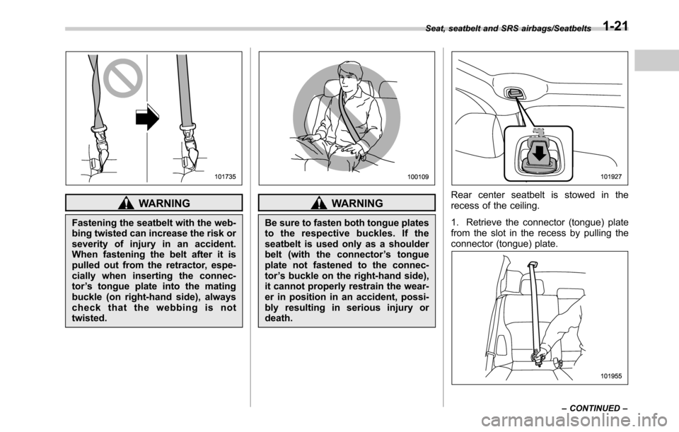
Fastening the seatbelt with the web-
bing twisted can increase the risk or
severity of injury in an accident.
When fastening the belt after it is
pulled out from the retractor, espe-
cially when inserting the connec-
tor’s tongue plate into the mating
buckle (on right-hand side), always
check that the webbing is not
twisted.
WARNING
Be sure to fasten both tongue plates
to the respective buckles. If the
seatbelt is used only as a shoulder
belt (with the connector’s tongue
plate not fastened to the connec-
tor’s buckle on the right-hand side),
it cannot properly restrain the wear-
er in position in an accident, possi-
bly resulting in serious injury or
death.
Rear center seatbelt is stowed in the
recess of the ceiling.
1. Retrieve the connector (tongue) plate
from the slot in the recess by pulling the
connector (tongue) plate.
Seat, seatbelt and SRS airbags/Seatbelts
–CONTINUED–1-21
Page 74 of 572
Seat, seatbelt and SRS airbags/*SRS airbag (Supplemental Restraint System airbag)
WARNING
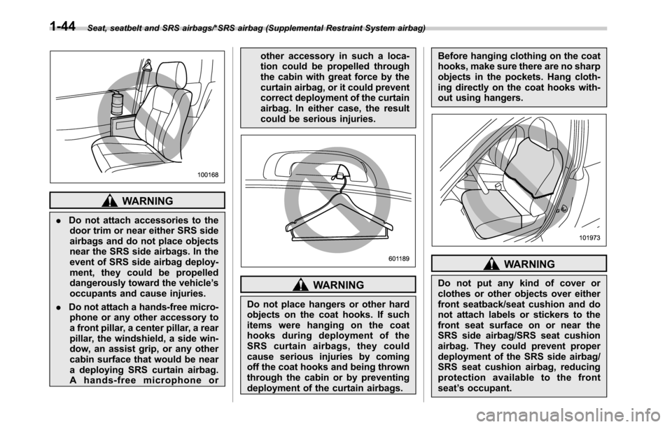
.Do not attach accessories to the
door trim or near either SRS side
airbags and do not place objects
near the SRS side airbags. In the
event of SRS side airbag deploy-
ment, they could be propelled
dangerously toward the vehicle’s
occupants and cause injuries.
.Do not attach a hands-free micro-
phone or any other accessory to
a front pillar, a center pillar, a rear
pillar, the windshield, a side win-
dow, an assist grip, or any other
cabin surface that would be near
a deploying SRS curtain airbag.
A hands-free microphone orother accessory in such a loca-
tion could be propelled through
the cabin with great force by the
curtain airbag, or it could prevent
correct deployment of the curtain
airbag. In either case, the result
could be serious injuries.
WARNING
Do not place hangers or other hard
objects on the coat hooks. If such
items were hanging on the coat
hooks during deployment of the
SRS curtain airbags, they could
cause serious injuries by coming
off the coat hooks and being thrown
through the cabin or by preventing
deployment of the curtain airbags.Before hanging clothing on the coat
hooks, make sure there are no sharp
objects in the pockets. Hang cloth-
ing directly on the coat hooks with-
out using hangers.
WARNING
Do not put any kind of cover or
clothes or other objects over either
front seatback/seat cushion and do
not attach labels or stickers to the
front seat surface on or near the
SRS side airbag/SRS seat cushion
airbag. They could prevent proper
deployment of the SRS side airbag/
SRS seat cushion airbag, reducing
protection available to the front
seat’s occupant.
1-44
Page 78 of 572
Seat, seatbelt and SRS airbags/*SRS airbag (Supplemental Restraint System airbag)
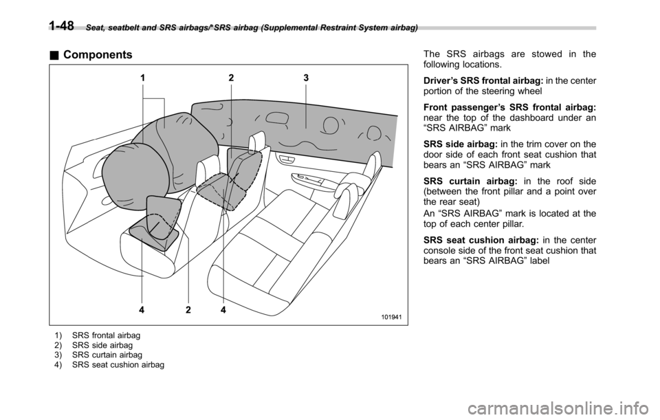
&Components
1) SRS frontal airbag
2) SRS side airbag
3) SRS curtain airbag
4) SRS seat cushion airbag
The SRS airbags are stowed in the
following locations.
Driver’s SRS frontal airbag:in the center
portion of the steering wheel
Front passenger’s SRS frontal airbag:
near the top of the dashboard under an
“SRS AIRBAG”mark
SRS side airbag:in the trim cover on the
door side of each front seat cushion that
bears an“SRS AIRBAG”mark
SRS curtain airbag:in the roof side
(between the front pillar and a point over
the rear seat)
An“SRS AIRBAG”mark is located at the
top of each center pillar.
SRS seat cushion airbag:in the center
console side of the front seat cushion that
bears an“SRS AIRBAG”label
1-48
Page 108 of 572
Keys and doors/Door locks
Door locks
&Locking and unlocking from
the outside
NOTE
If you unlock the driver’s door with a
key (including a mechanical key) and
open the door while the alarm system
is armed, the alarm system is triggered
and the vehicle’s horn sounds. In this
case, perform any of the following
operations:
Models with“keyless access with
push-button start system”:
.Press any button on the access key
(except when the access key battery is
discharged).
.Turn the push-button ignition switch
to the“ACC”position.
.Carry the access key and perform
either of the following procedures.
–Grip the front door handle
–Press the rear gate opener button
Models without“keyless access with
push-button start system”:
.Press any button on the remote
transmitter (except when the transmit-
ter battery is discharged).
.Insert the key into the ignition
switch and turn the ignition switch tothe“ON”position.
For details about the alarm system,
refer to“Alarm system”F2-28.
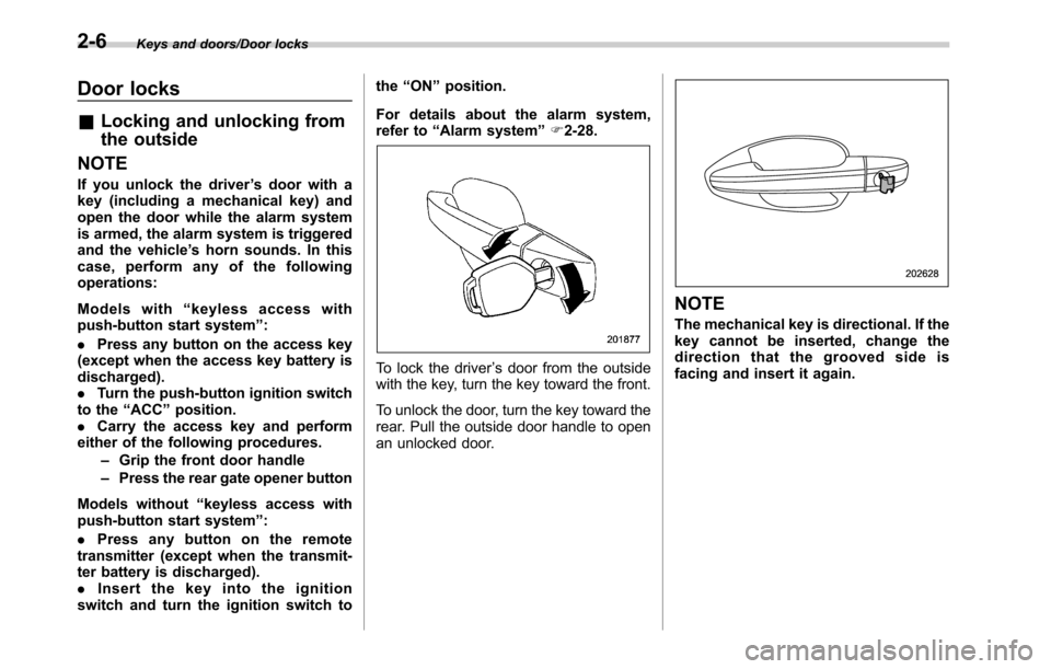
To lock the driver’s door from the outside
with the key, turn the key toward the front.
To unlock the door, turn the key toward the
rear. Pull the outside door handle to open
an unlocked door.
NOTE
The mechanical key is directional. If the
key cannot be inserted, change the
direction that the grooved side is
facing and insert it again.
2-6
Page 116 of 572

Keys and doors/Keyless access with push–button start system
Outback
1) Antenna
2) Operating range
.The operating range of the door lock-
ing/unlocking function is approximately 16
to 32 in (40 to 80 cm) from the respective
door handle.
.For Legacy,the operating range of the
trunk opening function is approximately 16
to 32 in (40 to 80 cm) from the trunk
opener button.
.For Outback,the operating range of
the rear gate locking/unlocking function is
approximately 16 to 32 in (40 to 80 cm)
from the rear gate ornament.
1) LED indicator
When the access key is within either of the
operating ranges of the front doors, the
LED indicator on the access key flashes.
When the keyless access functions are
disabled, the LED indicator does not flash
unless a button on the access key is
pressed.
!Operating range tips
.Locking by using the keyless access
function can be operated only by the door
lock sensor in the operating range in
which the access key is detected.
.Unlocking by using the keyless access
function can be operated only by the door
handle in the operating range in which the
access key is detected.
.If the access key is placed too close tothe vehicle body, the keyless access
functions may not operate properly. If they
do not operate properly, repeat the opera-
tion from further away.
.If the access key is placed near the
ground or in an elevated location from the
ground, even if it is in the indicated
operating range, the keyless access func-
tion may not operate properly.
.When the access key is within the
operating range, it is possible for anyone,
even someone who is not carrying the
access key, to operate the keyless access
function. Note that the keyless access
function can be operated only by the door
handle, door lock sensor, rear gate opener
button, trunk opener button or rear lock
button in the operating range in which the
access key is detected.
.It is not possible to lock the doors and
rear gate using the keyless access func-
tion when the access key is inside the
vehicle. However, depending on the status
of the access key and the environmental
conditions, the access key may be locked
inside the vehicle. Before locking, make
sure that you have the access key.
.When the battery of the access key is
discharged, or when operating it in a
location with strong radio waves or noise
(e.g., near a radio tower, power plant,
broadcast station or an area where wire-
2-14
Page 126 of 572
Keys and doors/Remote keyless entry system
key is used as the transmitter for the
remote keyless entry system. For models
without“keyless access with push-button
start system”, the transmitter for the
remote keyless entry system is located
inside the key head.
The remote keyless entry system has the
following functions.
.Locking and unlocking the doors (and
rear gate for Outback) without a key
.Opening the trunk lid (Legacy) without
key
.Sounding a panic alarm
.Arming and disarming the alarm sys-
tem. For detailed information, refer to
“Alarm system”F2-28.
The operable distance of the remote
keyless entry system is approximately 30
feet (10 meters). However, this distance
will vary depending on environmental
conditions. The system’s operable dis-
tance will be shorter in areas near a
facility or electronic equipment emitting
strong radio waves such as a power plant,
broadcast station, TV tower, or remote
controller of home electronic appliances.&Operating the access key
NOTE
The remote keyless entry system will
not be activated when the push-button
ignition switch is in any position other
than the“OFF”position.
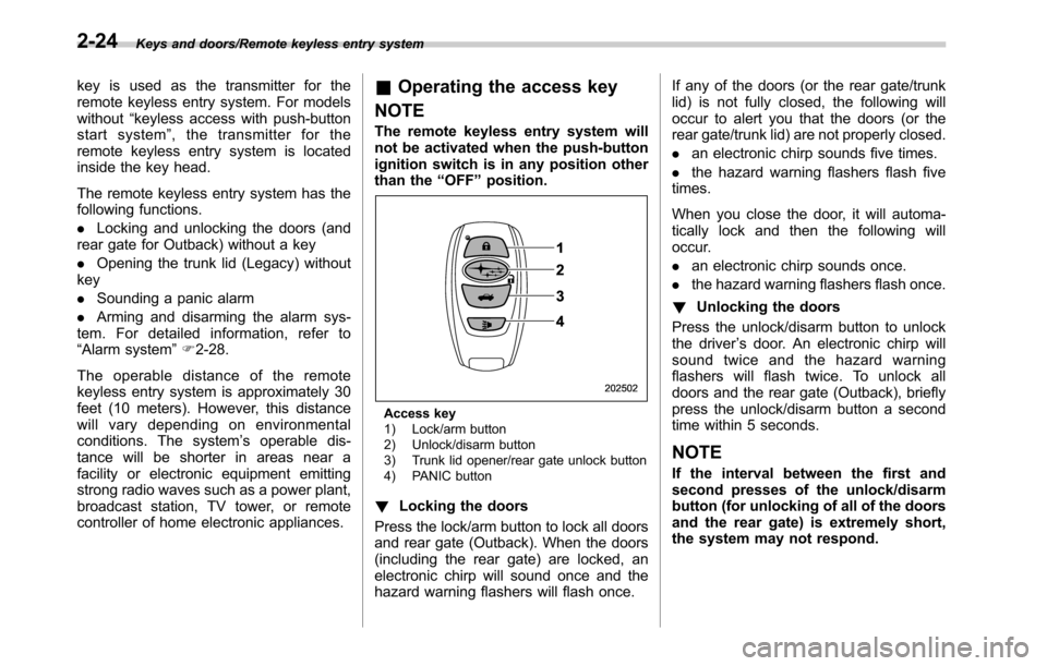
Access key
1) Lock/arm button
2) Unlock/disarm button
3) Trunk lid opener/rear gate unlock button
4) PANIC button
!Locking the doors
Press the lock/arm button to lock all doors
and rear gate (Outback). When the doors
(including the rear gate) are locked, an
electronic chirp will sound once and the
hazard warning flashers will flash once.If any of the doors (or the rear gate/trunk
lid) is not fully closed, the following will
occur to alert you that the doors (or the
rear gate/trunk lid) are not properly closed.
.an electronic chirp sounds five times.
.the hazard warning flashers flash five
times.
When you close the door, it will automa-
tically lock and then the following will
occur.
.an electronic chirp sounds once.
.the hazard warning flashers flash once.
!Unlocking the doors
Press the unlock/disarm button to unlock
the driver’s door. An electronic chirp will
sound twice and the hazard warning
flashers will flash twice. To unlock all
doors and the rear gate (Outback), briefly
press the unlock/disarm button a second
time within 5 seconds.
NOTE
If the interval between the first and
second presses of the unlock/disarm
button (for unlocking of all of the doors
and the rear gate) is extremely short,
the system may not respond.
2-24
Page 155 of 572
Ignition switch (models with-
out push-button start sys-
tem)
WARNING
.Never turn the ignition switch to
“LOCK”while the vehicle is
being driven or towed because
that will lock the steering wheel,
preventing steering control. And
when the engine is turned off, it
takes a much greater effort than
usual to steer.
.Before leaving the vehicle, al-
ways remove the key from the
ignition switch for safety and
never allow an unattended child
to remain in the vehicle. Failure
to follow this procedure could
result in injury to a child or
others. Children could operate
the power windows, the moon-
roof or other controls or even
make the vehicle move.
CAUTION
Do not attach a large key holder or
key case to either key. If it bangedagainst your knees or hands while
you are driving, it could turn the
ignition switch from the“ON”posi-
tion to the“ACC”or“LOCK”posi-
tion, thereby stopping the engine.
Also, if the key is attached to a
keyholder or to a large bunch of
other keys, centrifugal force may act
on it as the vehicle moves, resulting
in unwanted turning of the ignition
switch.
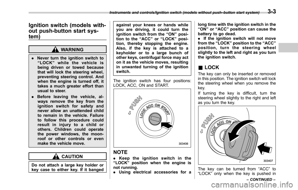
The ignition switch has four positions:
LOCK, ACC, ON and START.
NOTE
.Keep the ignition switch in the
“LOCK”position when the engine is
not running.
.Using electrical accessories for along time with the ignition switch in the
“ON”or“ACC”position can cause the
battery to go dead.
.If the ignition switch will not move
from the“LOCK”position to the“ACC”
position, turn the steering wheel
slightly to the left and right as you turn
the ignition switch.
&LOCK
The key can only be inserted or removed
in this position. The ignition switch will lock
the steering wheel when you remove the
key.
If turning the key is difficult, turn the
steering wheel slightly to the right and left
as you turn the key.
The key can be turned from“ACC”to
“LOCK”only when the key is pushed in
Instruments and controls/Ignition switch (models without push–button start system)
–CONTINUED–3-3
Page 167 of 572
&CHECK ENGINE
warning light/Malfunc-
tion indicator light
CAUTION
If the CHECK ENGINE warning light/
malfunction indicator light illumi-
nates while you are driving, have
your vehicle checked/repaired by
your SUBARU dealer as soon as
possible. Continued vehicle opera-
tion without having the emission
control system checked and re-
paired as necessary could cause
serious damage, which may not be
covered by your vehicle’s warranty.
If this light illuminates steadily or blinks
while the engine is running, it may indicate
that there is a problem or potential
problem somewhere in the emission con-
trol system.
!If the light illuminates constantly
If the light illuminates constantly while
driving or does not turn off after the engine
starts, an emission control system mal-
function has been detected.
You should have your vehicle checked by
an authorized SUBARU dealer immedi-
ately.
NOTE
This light also illuminates when the fuel
filler cap is not tightened until it clicks.
If you have recently refueled your vehicle,
the cause of the CHECK ENGINE warning
light/malfunction indicator light coming on
could be a loose or missing fuel filler cap.
Remove the cap and retighten it until it
clicks. Make sure nothing is interfering
with the sealing of the cap. Tightening the
cap will not make the CHECK ENGINE
warning light/malfunction indicator light
turn off immediately. It may take several
driving trips. If the light does not turn off,
take your vehicle to your authorized
SUBARU dealer immediately.
!If the light is blinking
If the light is blinking while driving, an
engine misfire condition has been de-
tected which may damage the emission
control system.
To prevent serious damage to the emis-
sion control system, you should conform
to the following instructions.
.Reduce vehicle speed.
.Avoid hard acceleration.
.Avoid steep uphill grades.
.Reduce the amount of cargo, if possi-
ble.
.Stop towing a trailer as soon as
possible.The CHECK ENGINE warning light/mal-
function indicator light may stop blinking
and illuminate steadily after several driv-
ing trips. You should have your vehicle
checked by an authorized SUBARU deal-
er immediately.
&Charge warning light
If this light illuminates when the engine is
running, it may indicate that the charging
system is not working properly.
If the light illuminates while driving or does
not turn off after the engine starts, stop the
engine at the first safe opportunity and
check the alternator belt. If the belt is
loose, broken or if the belt is in good
condition but the light remains illuminated,
contact your nearest SUBARU dealer
immediately.
&Oil pressure warning
light
CAUTION
Do not operate the engine with the
oil pressure warning light on. This
may cause serious engine damage.
If this light illuminates when the engine is
running, it may indicate that the engine oil
pressure is low and the lubricating system
Instruments and controls/Warning and indicator lights
–CONTINUED–3-15