SUBARU LEGACY 2017 6.G Owners Manual
Manufacturer: SUBARU, Model Year: 2017, Model line: LEGACY, Model: SUBARU LEGACY 2017 6.GPages: 610
Page 361 of 610
Interior equipment/Cargo area cover (Outback–if equipped)
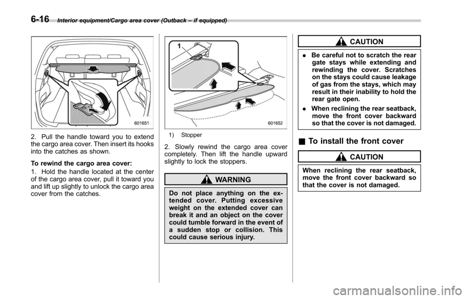
2. Pull the handle toward you to extend
the cargo area cover. Then insert its hooks
into the catches as shown.
To rewind the cargo area cover:
1. Hold the handle located at the center
of the cargo area cover, pull it toward you
and lift up slightly to unlock the cargo area
cover from the catches.1) Stopper
2. Slowly rewind the cargo area cover
completely. Then lift the handle upward
slightly to lock the stoppers.
WARNING
Do not place anything on the ex-
tended cover. Putting excessive
weight on the extended cover can
break it and an object on the cover
could tumble forward in the event of
a sudden stop or collision. This
could cause serious injury.
CAUTION
. Be careful not to scratch the rear
gate stays while extending and
rewinding the cover. Scratches
on the stays could cause leakage
of gas from the stays, which may
result in their inability to hold the
rear gate open.
. When reclining the rear seatback,
move the front cover backward
so that the cover is not damaged.
& To install the front cover
CAUTION
When reclining the rear seatback,
move the front cover backward so
that the cover is not damaged.
6-16
Page 362 of 610
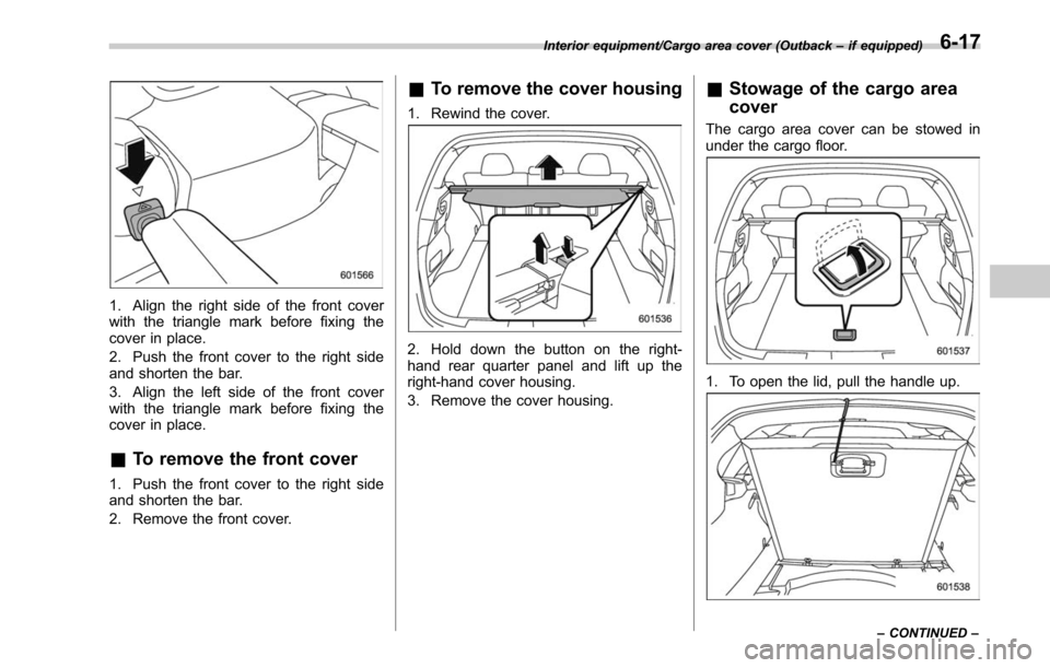
1. Align the right side of the front cover
with the triangle mark before fixing the
cover in place.
2. Push the front cover to the right side
and shorten the bar.
3. Align the left side of the front cover
with the triangle mark before fixing the
cover in place.
&To remove the front cover
1. Push the front cover to the right side
and shorten the bar.
2. Remove the front cover.
&To remove the cover housing
1. Rewind the cover.
2. Hold down the button on the right-
hand rear quarter panel and lift up the
right-hand cover housing.
3. Remove the cover housing.
&Stowage of the cargo area
cover
The cargo area cover can be stowed in
under the cargo floor.
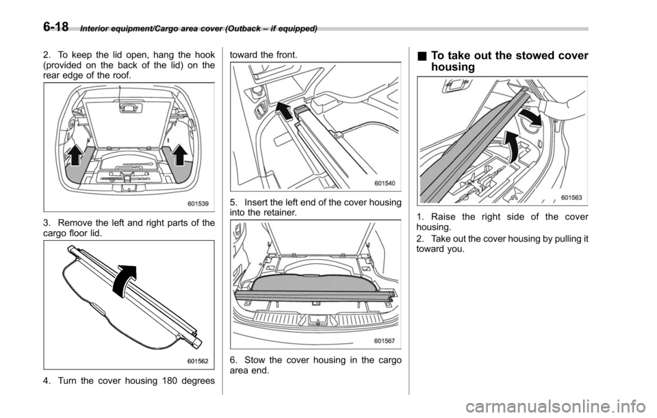
1. To open the lid, pull the handle up.
Interior equipment/Cargo area cover (Outback –if equipped)
–CONTINUED –6-17
Page 363 of 610
Interior equipment/Cargo area cover (Outback–if equipped)
2. To keep the lid open, hang the hook
(provided on the back of the lid) on the
rear edge of the roof.
3. Remove the left and right parts of the
cargo floor lid.
4. Turn the cover housing 180 degrees toward the front.
5. Insert the left end of the cover housing
into the retainer.
6. Stow the cover housing in the cargo
area end.
&
To take out the stowed cover
housing
1. Raise the right side of the cover
housing.
2. Take out the cover housing by pulling it
toward you.
6-18
Page 364 of 610
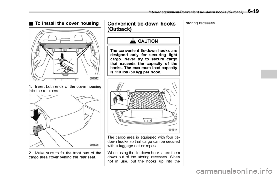
&To install the cover housing
1. Insert both ends of the cover housing
into the retainers.
2. Make sure to fix the front part of the
cargo area cover behind the rear seat.
Convenient tie-down hooks
(Outback)
CAUTION
The convenient tie-down hooks are
designed only for securing light
cargo. Never try to secure cargo
that exceeds the capacity of the
hooks. The maximum load capacity
is 110 lbs (50 kg) per hook.
The cargo area is equipped with four tie-
down hooks so that cargo can be secured
with a luggage net or ropes.
When using the tie-down hooks, turn them
down out of the storing recesses. When
not in use, put the hooks up into the storing recesses.
Interior equipment/Convenient tie
–down hooks (Outback)6-19
Page 365 of 610
Interior equipment/Under–floor storage compartment
Under-floor storage compart-
ment
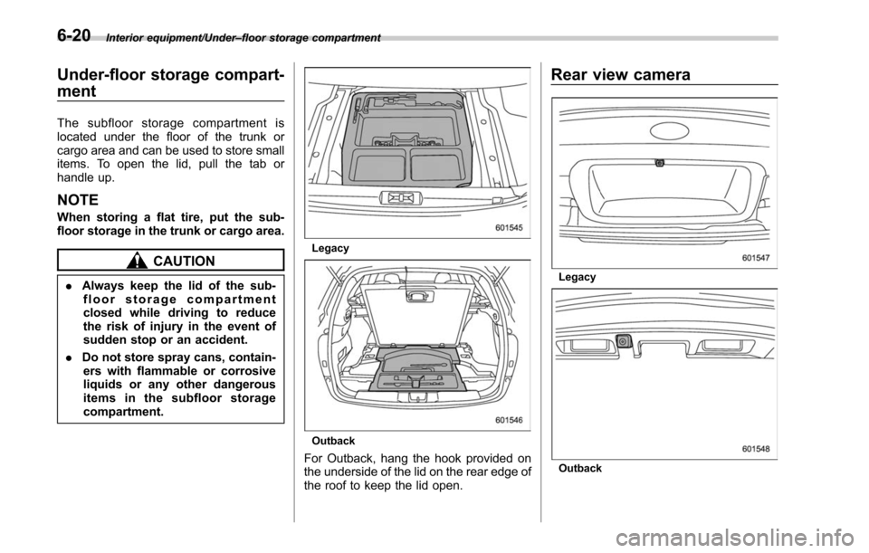
The subfloor storage compartment is
located under the floor of the trunk or
cargo area and can be used to store small
items. To open the lid, pull the tab or
handle up.
NOTE
When storing a flat tire, put the sub-
floor storage in the trunk or cargo area.
CAUTION
. Always keep the lid of the sub-
floor storage compartment
closed while driving to reduce
the risk of injury in the event of
sudden stop or an accident.
. Do not store spray cans, contain-
ers with flammable or corrosive
liquids or any other dangerous
items in the subfloor storage
compartment.
Legacy
Outback
For Outback, hang the hook provided on
the underside of the lid on the rear edge of
the roof to keep the lid open.
Rear view camera
Legacy
Outback
6-20
Page 366 of 610
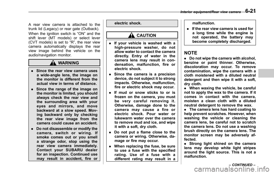
A rear view camera is attached to the
trunk lid (Legacy) or rear gate (Outback).
When the ignition switch is“ON ”and the
shift lever (MT models) or select lever
(CVT models) is set to “R”, the rear view
camera automatically displays the rear
view image behind the vehicle on the
audio/navigation monitor.
WARNING
. Since the rear view camera uses
a wide-angle lens, the image on
the monitor is different from the
actual view in terms of distance.
. Since the range of the image on
the monitor is limited, you should
always check the rear view and
the surrounding area with your
eyes and mirrors, and move
backward at a slow speed. Mov-
ing backward only by checking
the rear view image from the
camera could cause an accident.
. Do not disassemble or modify the
camera, switch or wiring. If
smoke comes out or you smell
a strange odor, stop using the
rear view camera immediately.
Contact your SUBARU dealer
for an inspection. Continued use
may result in accident, fire or electric shock.
CAUTION
.
If your vehicle is washed with a
high-pressure washer, do not
allow water to contact the camera
directly. Entry of water in the
camera lens may result in con-
densation, malfunction, fire or
electric shock.
. Since the camera is a precision
device, do not subject it to strong
impacts. Otherwise, malfunction,
fire or electric shock may occur.
. If mud or snow sticks to or is
frozen on the camera, you must
be very careful removing it.
Otherwise, damage done to the
camera may cause a fire or
electric shock. Pour water or
lukewarm water over the camera
to remove mud and ice, and wipe
it with a soft, dry cloth.
. Do not put a flame close to the
camera or wiring. Otherwise, da-
mage or fire may occur.
. When replacing the fuse, be sure
to use a fuse with the specified
rating. Use of a fuse with a
different rating may result in a malfunction.
. If the rear view camera is used for
a long time while the engine is
not operated, the battery may
become completely discharged.
NOTE
. Do not wipe the camera with alcohol,
benzine or paint thinner. Otherwise,
discoloration may occur. To remove
contamination, wipe the camera with a
cloth moistened with a diluted neutral
detergent and then wipe it with a soft,
dry cloth.
. When waxing the vehicle, be careful
not to apply the wax to the camera. If it
comes in contact with the camera,
moisten a clean cloth with a diluted
neutral detergent to remove the wax.
. The camera lens has hard coating to
help prevent scratches. However, when
washing the vehicle or cleaning the
camera lens, be careful not to scratch
the camera lens. Do not use a washing
brush directly on the camera lens. The
monitor screen may be adversely af-
fected.
. Strong light shined on the camera
lens may develop white light stripes
around the light source. This is not a
malfunction.
Interior equipment/Rear view camera
–CONTINUED –6-21
Page 367 of 610
Interior equipment/Rear view camera
.Under fluorescent lighting, the dis-
play may flicker. However, this is not a
malfunction.
. The image of the rear view camera
may be slightly different from the
actual color of the objects.
& How to use the rear view
camera
When performing the following procedure,
the rear view camera automatically dis-
plays the rear view image from the
vehicle.
1. Set the ignition switch to “ON”.
2. Set the shift lever or select lever to “R”.
When any of the following conditions
occur, the image before setting to “R”will
be displayed.
. Several seconds have passed after the
following operation (off delay function).
–Setting the shift lever to a position
other than “R”(MT models)
– Setting the select lever to a position
other than “P”or “R”(CVT models)
. The vehicle speed is more than 5 mph
(8 km/h).
. The select lever is set to “P”(CVT
models).
NOTE
. For models with the genuine
SUBARU navigation system or audio
system, the image of the rear view
camera has priority over other screen
displays. To operate other screens, set
the shift lever (MT models) or select
lever (CVT models) to a position other
than “R ”.
. The image of the rear view camera is
horizontally reversed as is the case
with the vehicle inside rear view mirror
or the side view mirror.
. It may be difficult to see the image of
the rear view camera in the following
cases. This is not a malfunction of the
camera.
–The vehicle is used for towing or
a trailer hitch is installed.
– The vehicle is in a dark place (at
night, in a tunnel, etc.).
– The vehicle is in an extremely hot
or cold place.
– An object (such as raindrops,
snow, dirt, etc.) that disturbs the
view of the rear view camera sticks
to the lens of the camera.
– Strong light shined directly on
the camera lens (occasionally, there
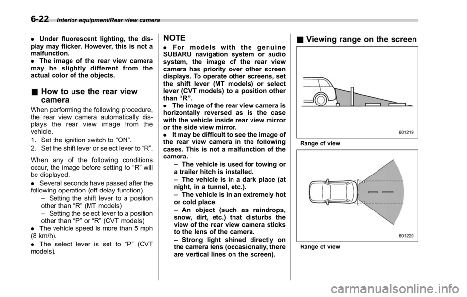
are vertical lines on the screen).& Viewing range on the screen
Range of view
Range of view
6-22
Page 368 of 610
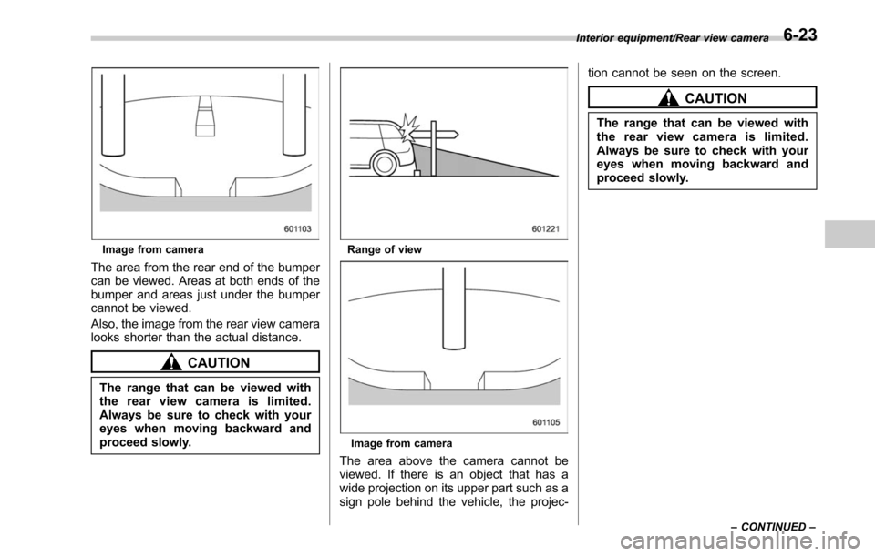
Image from camera
The area from the rear end of the bumper
can be viewed. Areas at both ends of the
bumper and areas just under the bumper
cannot be viewed.
Also, the image from the rear view camera
looks shorter than the actual distance.
CAUTION
The range that can be viewed with
the rear view camera is limited.
Always be sure to check with your
eyes when moving backward and
proceed slowly.
Range of view
Image from camera
The area above the camera cannot be
viewed. If there is an object that has a
wide projection on its upper part such as a
sign pole behind the vehicle, the projec-tion cannot be seen on the screen.
CAUTION
The range that can be viewed with
the rear view camera is limited.
Always be sure to check with your
eyes when moving backward and
proceed slowly.
Interior equipment/Rear view camera
–CONTINUED –6-23
Page 369 of 610
Interior equipment/Rear view camera
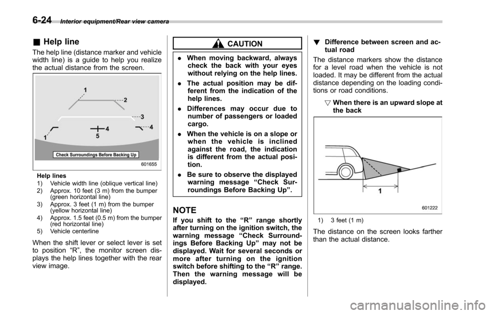
&Help line
The help line (distance marker and vehicle
width line) is a guide to help you realize
the actual distance from the screen.
Help lines
1) Vehicle width line (oblique vertical line)
2) Approx. 10 feet (3 m) from the bumper
(green horizontal line)
3) Approx. 3 feet (1 m) from the bumper (yellow horizontal line)
4) Approx. 1.5 feet (0.5 m) from the bumper (red horizontal line)
5) Vehicle centerline
When the shift lever or select lever is set
to position “R”, the monitor screen dis-
plays the help lines together with the rear
view image.
CAUTION
. When moving backward, always
check the back with your eyes
without relying on the help lines.
. The actual position may be dif-
ferent from the indication of the
help lines.
. Differences may occur due to
number of passengers or loaded
cargo.
. When the vehicle is on a slope or
when the vehicle is inclined
against the road, the indication
is different from the actual posi-
tion.
. Be sure to observe the displayed
warning message “Check Sur-
roundings Before Backing Up ”.
NOTE
If you shift to the “R ” range shortly
after turning on the ignition switch, the
warning message “Check Surround-
ings Before Backing Up” may not be
displayed. Wait for several seconds or
more after turning on the ignition
switch before shifting to the “R ” range.
Then the warning message will be
displayed. !
Difference between screen and ac-
tual road
The distance markers show the distance
for a level road when the vehicle is not
loaded. It may be different from the actual
distance depending on the loading condi-
tions or road conditions.
!When there is an upward slope at
the back1) 3 feet (1 m)
The distance on the screen looks farther
than the actual distance.
6-24
Page 370 of 610
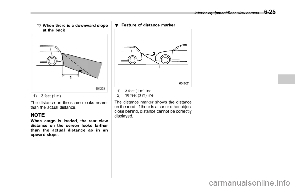
!When there is a downward slope
at the back
1) 3 feet (1 m)
The distance on the screen looks nearer
than the actual distance.
NOTE
When cargo is loaded, the rear view
distance on the screen looks farther
than the actual distance as in an
upward slope. !
Feature of distance marker
1) 3 feet (1 m) line
2) 10 feet (3 m) line
The distance marker shows the distance
on the road. If there is a car or other object
close behind, distance cannot be correctly
displayed.
Interior equipment/Rear view camera6-25