clock SUBARU OUTBACK 2007 4.G User Guide
[x] Cancel search | Manufacturer: SUBARU, Model Year: 2007, Model line: OUTBACK, Model: SUBARU OUTBACK 2007 4.GPages: 442, PDF Size: 13.39 MB
Page 196 of 442
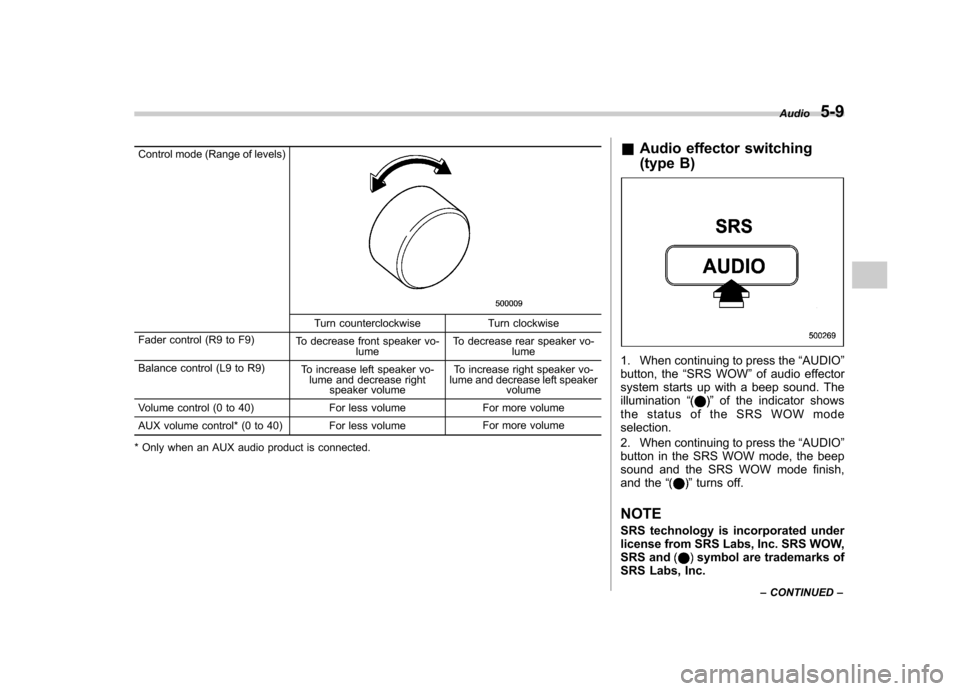
Control mode (Range of levels)
Turn counterclockwise Turn clockwise
Fader control (R9 to F9) To decrease front speaker vo-
lume To decrease rear speaker vo-
lume
Balance control (L9 to R9) To increase left speaker vo-
lume and decrease right speaker volume To increase right speaker vo-
lume and decrease left speaker volume
Volume control (0 to 40) For less volume For more volume
AUX volume control* (0 to 40) For less volume For more volume
* Only when an AUX audio product is connected. &
Audio effector switching
(type B)
1. When continuing to press the “AUDIO ”
button, the “SRS WOW ”of audio effector
system starts up with a beep sound. The illumination “
”of the indicator shows
the status of the SRS WOW mode selection.
2. When continuing to press the “AUDIO ”
button in the SRS WOW mode, the beep
sound and the SRS WOW mode finish,
and the “
”turns off.
NOTE
SRS technology is incorporated under
license from SRS Labs, Inc. SRS WOW,
SRS and
symbol are trademarks of
SRS Labs, Inc. Audio
5-9
– CONTINUED –
Page 220 of 442
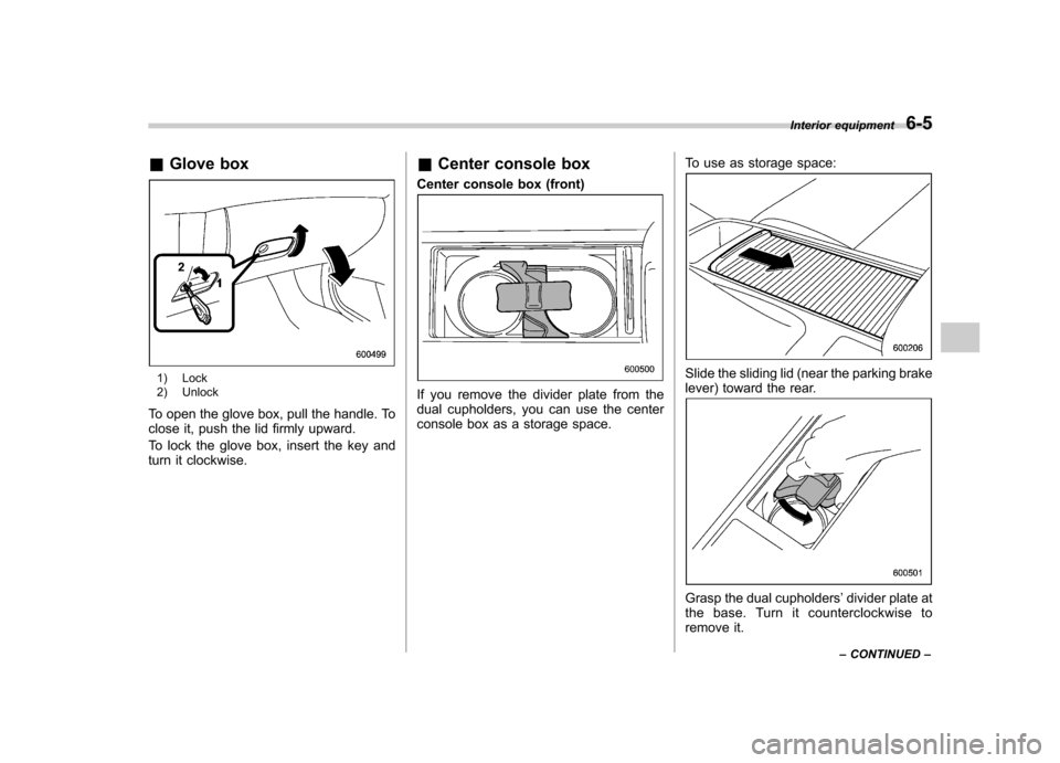
&Glove box
1) Lock
2) Unlock
To open the glove box, pull the handle. To
close it, push the lid firmly upward.
To lock the glove box, insert the key and
turn it clockwise. &
Center console box
Center console box (front)
If you remove the divider plate from the
dual cupholders, you can use the center
console box as a storage space. To use as storage space:
Slide the sliding lid (near the parking brake
lever) toward the rear.
Grasp the dual cupholders
’divider plate at
the base. Turn it counterclockwise to
remove it. Interior equipment
6-5
– CONTINUED –
Page 221 of 442
6-6Interior equipment
CAUTION
If you hold the divider plate at the
top while turning it counterclock-
wise, it may break.
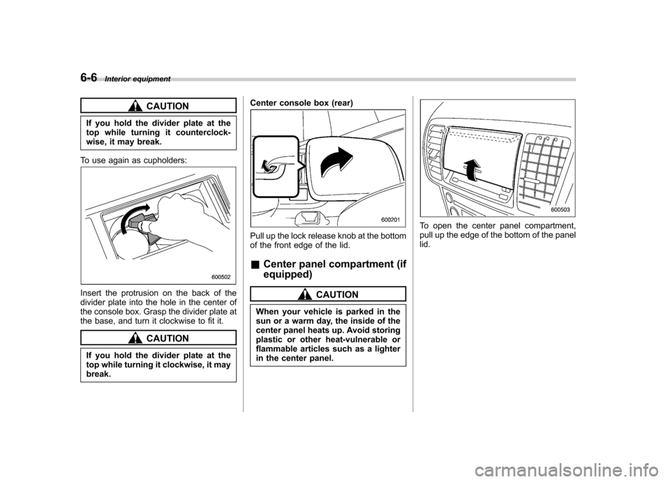
To use again as cupholders:
Insert the protrusion on the back of the
divider plate into the hole in the center of
the console box. Grasp the divider plate at
the base, and turn it clockwise to fit it.
CAUTION
If you hold the divider plate at the
top while turning it clockwise, it maybreak. Center console box (rear)
Pull up the lock release knob at the bottom
of the front edge of the lid. &
Center panel compartment (if equipped)
CAUTION
When your vehicle is parked in the
sun or a warm day, the inside of the
center panel heats up. Avoid storing
plastic or other heat-vulnerable or
flammable articles such as a lighter
in the center panel.
To open the center panel compartment,
pull up the edge of the bottom of the panellid.
Page 243 of 442
7-6Starting and operating
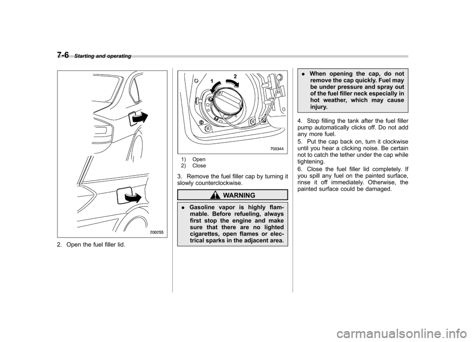
2. Open the fuel filler lid.
1) Open
2) Close
3. Remove the fuel filler cap by turning it
slowly counterclockwise.
WARNING
. Gasoline vapor is highly flam-
mable. Before refueling, always
first stop the engine and make
sure that there are no lighted
cigarettes, open flames or elec-
trical sparks in the adjacent area. .
When opening the cap, do not
remove the cap quickly. Fuel may
be under pressure and spray out
of the fuel filler neck especially in
hot weather, which may cause
injury.
4. Stop filling the tank after the fuel filler
pump automatically clicks off. Do not add
any more fuel.
5. Put the cap back on, turn it clockwise
until you hear a clicking noise. Be certain
not to catch the tether under the cap whiletightening.
6. Close the fuel filler lid completely. If
you spill any fuel on the painted surface,
rinse it off immediately. Otherwise, the
painted surface could be damaged.
Page 323 of 442
9-6In case of emergency
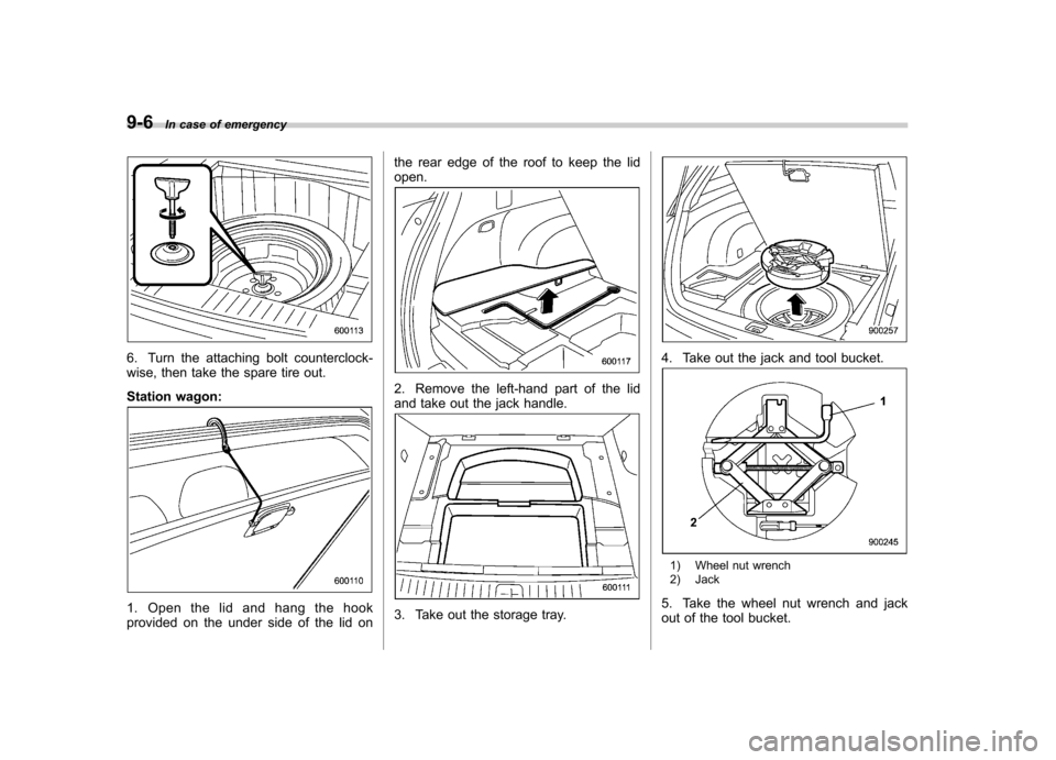
6. Turn the attaching bolt counterclock-
wise, then take the spare tire out.
Station wagon:
1. Open the lid and hang the hook
provided on the under side of the lid on the rear edge of the roof to keep the lidopen.
2. Remove the left-hand part of the lid
and take out the jack handle.
3. Take out the storage tray.
4. Take out the jack and tool bucket.
1) Wheel nut wrench
2) Jack
5. Take the wheel nut wrench and jack
out of the tool bucket.
Page 324 of 442
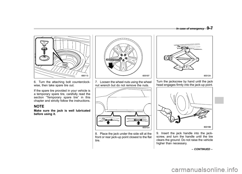
6. Turn the attaching bolt counterclock-
wise, then take spare tire out.
If the spare tire provided in your vehicle is
a temporary spare tire, carefully read thesection“Temporary spare tire ”in this
chapter and strictly follow the instructions. NOTE
Make sure the jack is well lubricated
before using it.7. Loosen the wheel nuts using the wheel
nut wrench but do not remove the nuts.
8. Place the jack under the side sill at the
front or rear jack-up point closest to the flattire.
Turn the jackscrew by hand until the jack
head engages firmly into the jack-up point.
9. Insert the jack handle into the jack-
screw, and turn the handle until the tire
clears the ground. Do not raise the vehicle
higher than necessary. In case of emergency
9-7
– CONTINUED –
Page 325 of 442
9-8In case of emergency
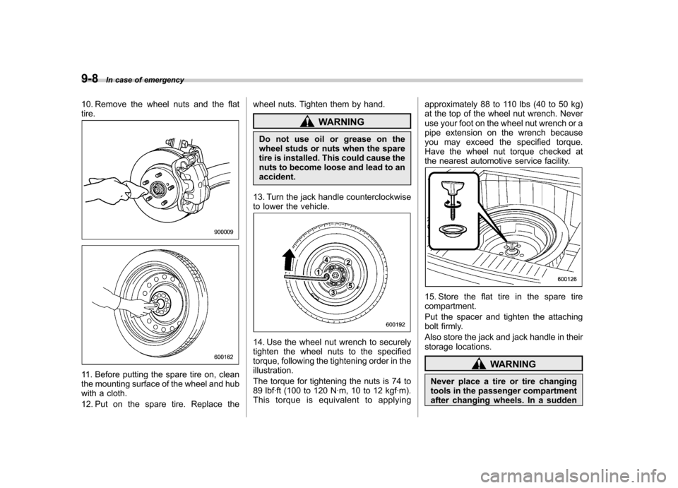
10. Remove the wheel nuts and the flat tire.
11. Before putting the spare tire on, clean
the mounting surface of the wheel and hub
with a cloth.
12. Put on the spare tire. Replace the wheel nuts. Tighten them by hand.
WARNING
Do not use oil or grease on the
wheel studs or nuts when the spare
tire is installed. This could cause the
nuts to become loose and lead to anaccident.
13. Turn the jack handle counterclockwise
to lower the vehicle.
14. Use the wheel nut wrench to securely
tighten the wheel nuts to the specified
torque, following the tightening order in the illustration.
The torque for tightening the nuts is 74 to
89 lbf·ft (100 to 120 N·m, 10 to 12 kgf·m).
This torque is equivalent to applying approximately 88 to 110 lbs (40 to 50 kg)
at the top of the wheel nut wrench. Never
use your foot on the wheel nut wrench or a
pipe extension on the wrench because
you may exceed the specified torque.
Have the wheel nut torque checked at
the nearest automotive service facility.
15. Store the flat tire in the spare tire compartment.
Put the spacer and tighten the attaching
bolt firmly.
Also store the jack and jack handle in their
storage locations.
WARNING
Never place a tire or tire changing
tools in the passenger compartment
after changing wheels. In a sudden
Page 329 of 442
9-12In case of emergency
5. Start the engine of the vehicle with the
booster battery and run it at moderate
speed. Then start the engine of the vehicle
that has the discharged battery.
6. When finished, carefully disconnect
the cables in exactly the reverse order. Engine overheating
WARNING
Never attempt to remove the radia-
tor cap until the engine has been
shut off and has fully cooled down.
When the engine is hot, the coolant
is under pressure. Removing the
cap while the engine is still hot
could release a spray of boiling hot
coolant, which could burn you very
seriously.
If the engine overheats, pull off the road
safely and stop the vehicle in a safe place. & If steam is coming from the
engine compartment
Turn off the engine and get everyone
away from the vehicle until it cools down. & If no steam is coming from
the engine compartment
1. Keep the engine running at idling speed.
2. Open the hood to ventilate the engine compartment.
Confirm that the cooling fan is turning. If
the fan is not turning, immediately turn off the engine and contact your authorized
dealer for repair.
3. After the engine coolant temperature
has dropped, turn off the engine.
If the temperature gauge stays at the
overheated zone, turn off the engine.
4. After the engine has fully cooled down,
check the coolant level in the reservetank.
If the coolant level is below the
“MIN ”
mark, add coolant up to the “MAX ”mark.
5. If there is no coolant in the reserve
tank, add coolant to the reserve tank.
Then remove the radiator cap and fill the
radiator with coolant.
If you remove the radiator cap from a hot
radiator, first wrap a thick cloth around the
radiator cap, then turn the cap counter-
clockwise slowly without pressing down
until it stops. Release the pressure from
the radiator. After the pressure has been
fully released, remove the cap by pressing
down and turning it.
Page 354 of 442
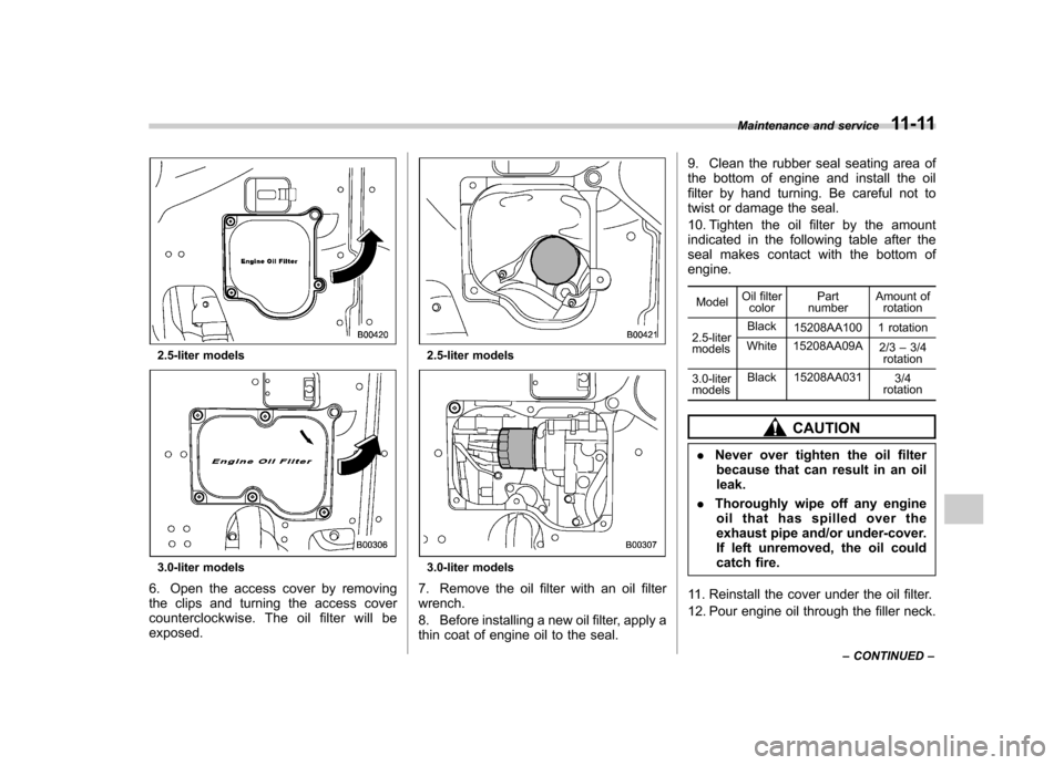
2.5-liter models
3.0-liter models
6. Open the access cover by removing
the clips and turning the access cover
counterclockwise. The oil filter will beexposed.
2.5-liter models
3.0-liter models
7. Remove the oil filter with an oil filter wrench.
8. Before installing a new oil filter, apply a
thin coat of engine oil to the seal. 9. Clean the rubber seal seating area of
the bottom of engine and install the oil
filter by hand turning. Be careful not to
twist or damage the seal.
10. Tighten the oil filter by the amount
indicated in the following table after the
seal makes contact with the bottom ofengine.
Model Oil filter
color Part
number Amount of
rotation
2.5-liter models Black
15208AA100 1 rotation
White 15208AA09A 2/3–3/4
rotation
3.0-liter models Black 15208AA031
3/4
rotation
CAUTION
. Never over tighten the oil filter
because that can result in an oil leak.
. Thoroughly wipe off any engine
oil that has spilled over the
exhaust pipe and/or under-cover.
If left unremoved, the oil could
catch fire.
11. Reinstall the cover under the oil filter.
12. Pour engine oil through the filler neck. Maintenance and service
11-11
– CONTINUED –
Page 387 of 442
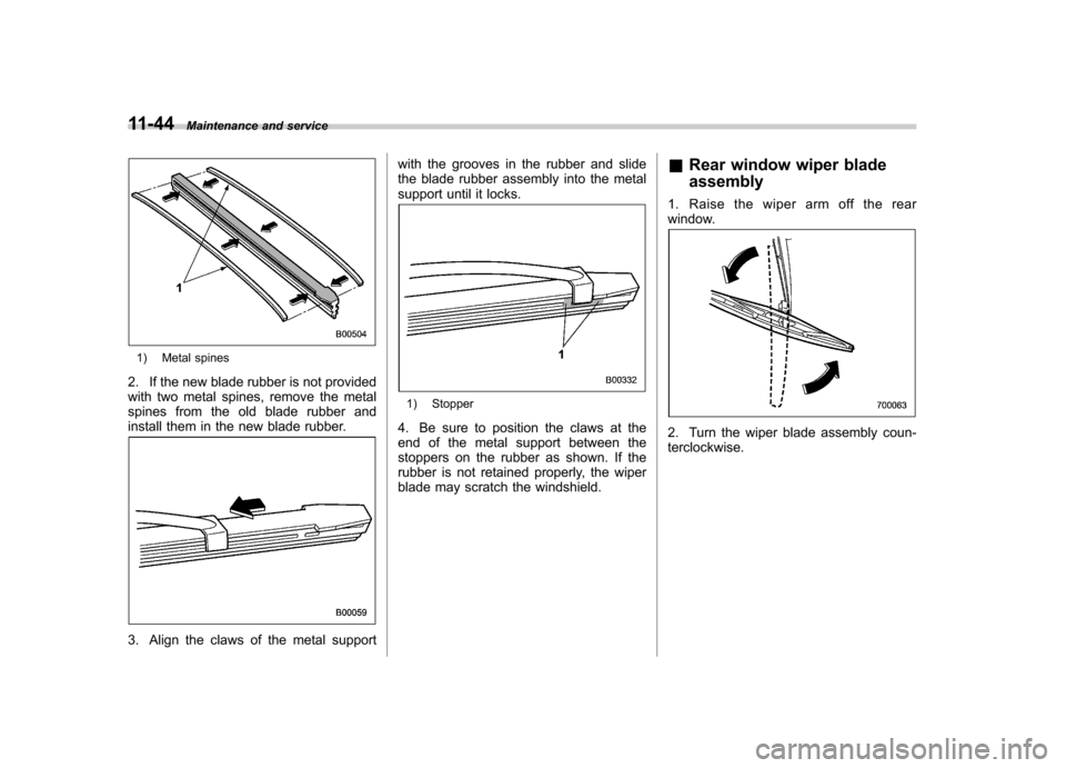
11-44Maintenance and service
1) Metal spines
2. If the new blade rubber is not provided
with two metal spines, remove the metal
spines from the old blade rubber and
install them in the new blade rubber.
3. Align the claws of the metal support with the grooves in the rubber and slide
the blade rubber assembly into the metal
support until it locks.
1) Stopper
4. Be sure to position the claws at the
end of the metal support between the
stoppers on the rubber as shown. If the
rubber is not retained properly, the wiper
blade may scratch the windshield. &
Rear window wiper blade assembly
1. Raise the wiper arm off the rear
window.
2. Turn the wiper blade assembly coun- terclockwise.