emergency SUBARU OUTBACK 2009 5.G Owners Manual
[x] Cancel search | Manufacturer: SUBARU, Model Year: 2009, Model line: OUTBACK, Model: SUBARU OUTBACK 2009 5.GPages: 447, PDF Size: 14.26 MB
Page 3 of 447

Warranties &Warranties for U.S.A.
All SUBARU vehicles distributed by
Subaru of America, Inc. and sold at retail
by an authorized SUBARU dealer in the
United States come with the followingwarranties: . SUBARU Limited Warranty
. Emission Control Systems Warranty
. Emissions Performance Warranty
All warranty information, including details
of coverage and exclusions, is in the“ Warranty and Maintenance Booklet ”.
Please read these warranties carefully.
& Warranties for Canada
All SUBARU vehicles distributed by
Subaru Canada, Inc. and sold at retail by
an authorized SUBARU dealer in Canada
come with the following warranties: . SUBARU Limited Warranty
. Anti-Corrosion Warranty
. Emission Control Warranty
All warranty information, including details
of coverage and exclusions, is in the“ Warranty and Service Booklet ”. Please
read these warranties carefully. How to use this Owner
’s
Manual & Using your Owner ’s Manual
Before you operate your vehicle, carefully
read this manual. To protect yourself and
extend the service life of your vehicle,
follow the instructions in this manual.
Failure to observe these instructions may
result in serious injury and damage to yourvehicle.
This manual is composed of fourteen
chapters. Each chapter begins with a brief
table of contents, so you can usually tell at
a glance if that chapter contains the
information you want.
Chapter 1: Seat, seatbelt and SRS airbags
This chapter informs you how to use the
seat and seatbelt and contains precau-
tions for the SRS airbags.
Chapter 2: Keys and doors
This chapter informs you how to operate
the keys, locks and windows.
Chapter 3: Instruments and controls
This chapter informs you about the opera-
tion of instrument panel indicators and
how to use the instruments and otherswitches. Chapter 4: Climate control
This chapter informs you how to operate
the climate control.
Chapter 5: Audio
This chapter informs you how to operate
your audio system.
Chapter 6: Interior equipment
This chapter informs you how to operate
interior equipment.
Chapter 7: Starting and operating
This chapter informs you how to start and
operate your SUBARU.
Chapter 8: Driving tips
This chapter informs you how to drive your
SUBARU in various conditions and ex-
plains some safety tips on driving.
Chapter 9: In case of emergency
This chapter informs you what to do if you
have a problem while driving, such as a
flat tire or engine overheating.
Chapter 10: Appearance care
This chapter informs you how to keep your
SUBARU looking good.
Chapter 11: Maintenance and service
This chapter informs you when you need
to take your SUBARU to the dealer for
scheduled maintenance and informs you
how to keep your SUBARU running
properly.1
– CONTINUED –
Page 11 of 447

Table of contents
Seat, seatbelt and SRS airbags1
Keys and doors2
Instruments and controls
Climate control4
Audio5
Interior equipment6
Starting and operating7
Driving tips8
In case of emergency9
Appearance care10
Maintenance and service11
Specifications12
Consumer information and Reporting safety defects13
Index14
3
Page 27 of 447
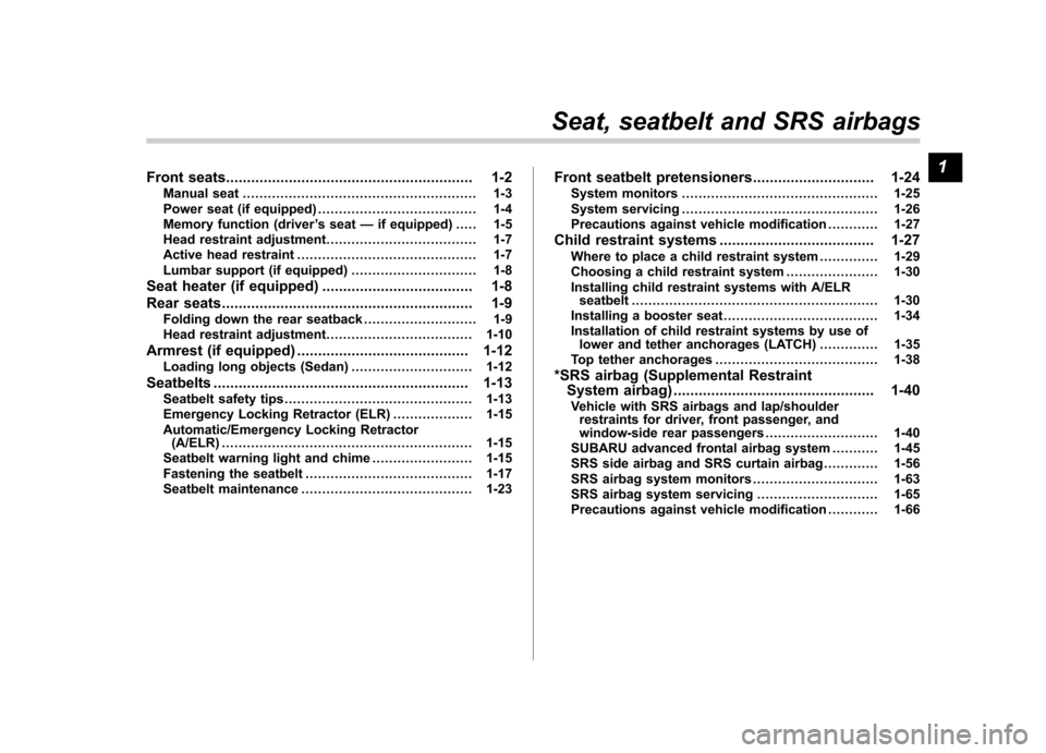
Front seats........................................................... 1-2
Manual seat ........................................................ 1-3
Power seat (if equipped) ...................................... 1-4
Memory function (driver ’s seat —if equipped) ..... 1-5
Head restraint adjustment .................................... 1-7
Active head restraint ........................................... 1-7
Lumbar support (if equipped) .............................. 1-8
Seat heater (if equipped) .................................... 1-8
Rear seats ............................................................ 1-9
Folding down the rear seatback ........................... 1-9
Head restraint adjustment ................................... 1-10
Armrest (if equipped) ......................................... 1-12
Loading long objects (Sedan) ............................. 1-12
Seatbelts ............................................................. 1-13
Seatbelt safety tips ............................................. 1-13
Emergency Locking Retractor (ELR) ................... 1-15
Automatic/Emergency Locking Retractor (A/ELR) ............................................................ 1-15
Seatbelt warning light and chime ........................ 1-15
Fastening the seatbelt ........................................ 1-17
Seatbelt maintenance ......................................... 1-23 Front seatbelt pretensioners
............................. 1-24
System monitors ............................................... 1-25
System servicing ............................................... 1-26
Precautions against vehicle modification ............ 1-27
Child restraint systems ..................................... 1-27
Where to place a child restraint system .............. 1-29
Choosing a child restraint system ...................... 1-30
Installing child restraint systems with A/ELR seatbelt ........................................................... 1-30
Installing a booster seat ..................................... 1-34
Installation of child restraint systems by use of lower and tether anchorages (LATCH) .............. 1-35
Top tether anchorages ....................................... 1-38
*SRS airbag (Supplemental Restraint System airbag) ................................................ 1-40
Vehicle with SRS airbags and lap/shoulder restraints for driver, front passenger, and
window-side rear passengers . .......................... 1-40
SUBARU advanced frontal airbag system ........... 1-45
SRS side airbag and SRS curtain airbag ............. 1-56
SRS airbag system monitors .............................. 1-63
SRS airbag system servicing ... .......................... 1-65
Precautions against vehicle modification ............ 1-66
Seat, seatbelt and SRS airbags1
Page 41 of 447
&Emergency Locking Retrac-
tor (ELR)
The driver ’s seatbelt has an Emergency
Locking Retractor (ELR).
The emergency locking retractor allows
normal body movement but the retractor
locks automatically during a sudden stop,
impact or if you pull the belt very quickly
out of the retractor. & Automatic/Emergency Lock-
ing Retractor (A/ELR)
Each passenger ’s seatbelt has an Auto-
matic/Emergency Locking Retractor (A/
ELR). The Automatic/Emergency Locking
Retractor normally functions as an Emer-
gency Locking Retractor (ELR). The A/
ELR has an additional locking mode“ Automatic Locking Retractor (ALR)
mode ”intended to secure a child restraint
system. When the seatbelt is once drawn
out completely and is then retracted even
slightly, the retractor locks the seatbelt in
that position and the seatbelt cannot be
extended. As the belt is rewinding, clicks
will be heard which indicate the retractor
functions as ALR. When the seatbelt is
retracted fully, ALR mode is released.
When securing a child restraint system on
the passengers ’seats, the seatbelt must
be changed over to the Automatic Locking Retractor (ALR) mode.
When the child restraint system is re-
moved, make sure that the retractor is
restored to the Emergency Locking Re-
tractor (ELR) function by allowing the
seatbelt to retract fully.
For instructions on how to convert the
retractor to the ALR mode and restore it to
the ELR mode, refer to the
“Child restraint
systems ”section in this chapter.
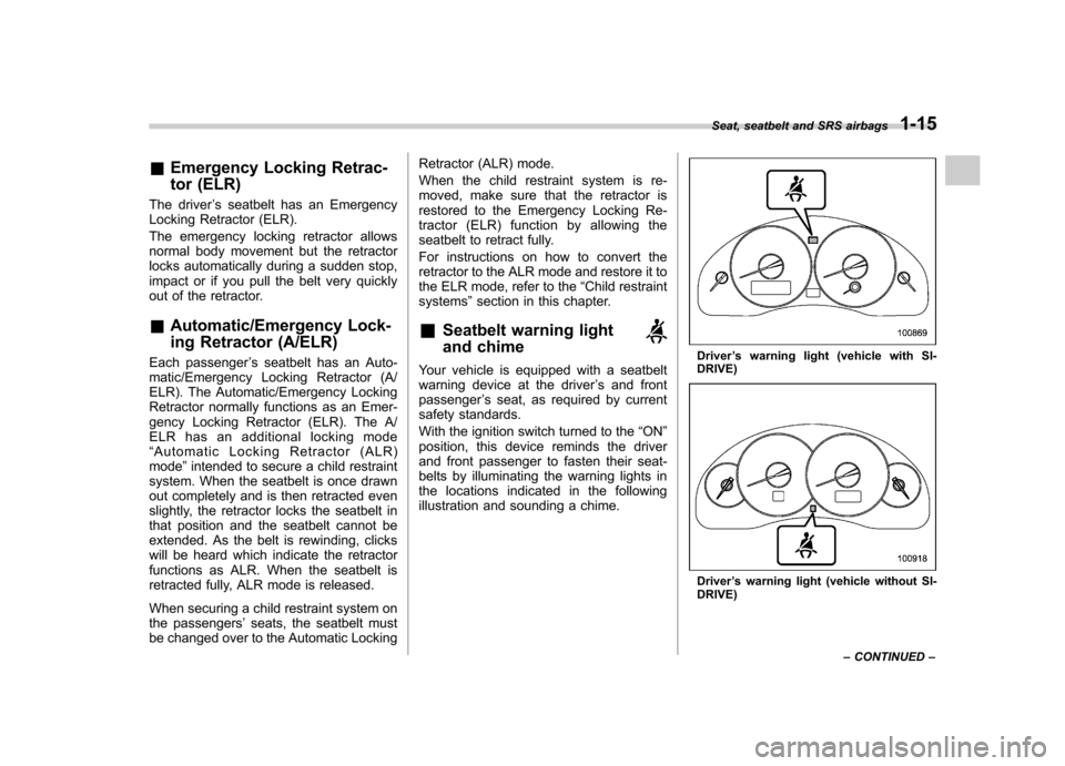
& Seatbelt warning light
and chime
Your vehicle is equipped with a seatbelt
warning device at the driver ’s and front
passenger ’s seat, as required by current
safety standards.
With the ignition switch turned to the “ON ”
position, this device reminds the driver
and front passenger to fasten their seat-
belts by illuminating the warning lights in
the locations indicated in the following
illustration and sounding a chime.Driver ’s warning light (vehicle with SI-
DRIVE)
Driver ’s warning light (vehicle without SI-
DRIVE) Seat, seatbelt and SRS airbags
1-15
– CONTINUED –
Page 55 of 447
&Where to place a child re-
straint system
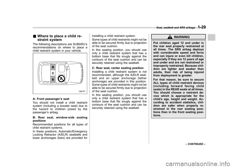
The following descriptions are SUBARU ’s
recommendations on where to place a
child restraint system in your vehicle.
A: Front passenger ’s seat
You should not install a child restraint
system (including a booster seat) due to
the hazard to children posed by thepassenger ’s airbag.
B: Rear seat, window-side seatingpositions
Recommended positions for all types of
child restraint systems.
In these positions, Automatic/Emergency
Locking Retractor (A/ELR) seatbelts and
lower anchorages (bars) are provided for installing a child restraint system.
Some types of child restraints might not be
able to be secured firmly due to projection
of the seat cushion.
In this seating position, you should use
only a child restraint system that has a
bottom base that fits snugly against the
contours of the seat cushion and can be
securely retained using the seatbelt.
C: Rear seat, center seating position
Installing a child restraint system is not
recommended, although the A/ELR seat-
belt and an upper anchorage (tether
anchorage) are provided in this position.
Some types of child restraints might not be
able to be secured firmly due to projection
of the seat cushion.
In this seating position, you should use
only a child restraint system that has a
bottom base that fits snugly against the
contours of the seat cushion and can be
securely retained using the seatbelt.
WARNING
Put children aged 12 and under in
the rear seat properly restrained at
all times. The SRS airbag deploys
with considerable speed and force
and can injure or even kill children,
especially if they are 12 years of age
and under and are not restrained or
improperly restrained. Because chil-
dren are lighter and weaker than
adults, their risk of being injured
from deployment is greater.
For that reason, be sure to secure
ALL types of child restraint devices
(including forward facing child
seats) in the REAR seats at all times.
You should choose a restraint de-
vice which is appropriate for thechild ’s age, height and weight. Ac-
cording to accident statistics, chil-
dren are safer when properly re-
strained in the rear seating posi-
tions than in the front seating posi-tions. Seat, seatbelt and SRS airbags
1-29
– CONTINUED –
Page 57 of 447
CAUTION
When you install a child restraint
system, follow the manufacturer ’s
instructions supplied with it. After
installing the child restraint system,
check to ensure that it is held
securely in position. If it is not held
tight and secure, the danger of your
child suffering personal injury in the
event of an accident may be in-creased.
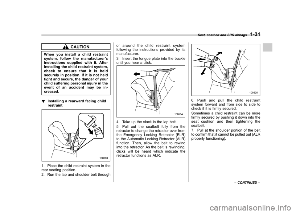
! Installing a rearward facing childrestraint
1. Place the child restraint system in the
rear seating position.
2. Run the lap and shoulder belt through or around the child restraint system
following the instructions provided by its
manufacturer.
3. Insert the tongue plate into the buckle
until you hear a click.
4. Take up the slack in the lap belt.
5. Pull out the seatbelt fully from the
retractor to change the retractor over from
the Emergency Locking Retractor (ELR)
to the Automatic Locking Retractor (ALR)
function. Then, allow the belt to rewind
into the retractor. As the belt is rewinding,
clicks will be heard which indicate the
retractor functions as ALR.
6. Push and pull the child restraint
system forward and from side to side to
check if it is firmly secured.
Sometimes a child restraint can be more
firmly secured by pushing it down into the
seat cushion and then tightening theseatbelt.
7. Pull at the shoulder portion of the belt
to confirm that it cannot be pulled out (ALR
properly functioning).
Seat, seatbelt and SRS airbags
1-31
– CONTINUED –
Page 58 of 447
1-32Seat, seatbelt and SRS airbags
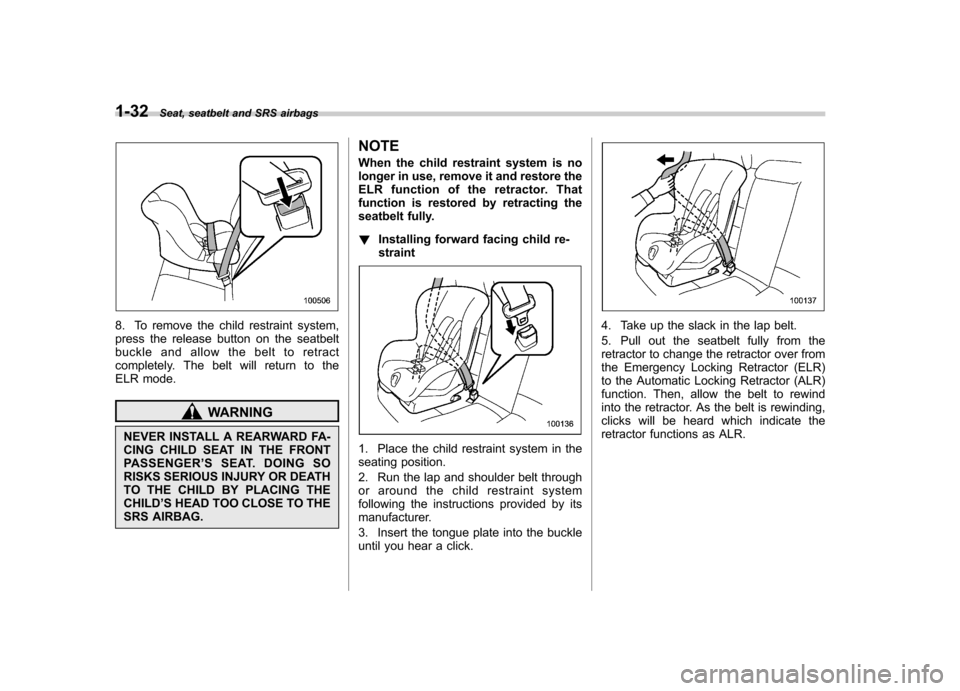
8. To remove the child restraint system,
press the release button on the seatbelt
buckle and allow the belt to retract
completely. The belt will return to the
ELR mode.
WARNING
NEVER INSTALL A REARWARD FA-
CING CHILD SEAT IN THE FRONT
PASSENGER ’SSEAT.DOINGSO
RISKS SERIOUS INJURY OR DEATH
TO THE CHILD BY PLACING THECHILD ’S HEAD TOO CLOSE TO THE
SRS AIRBAG. NOTE
When the child restraint system is no
longer in use, remove it and restore the
ELR function of the retractor. That
function is restored by retracting the
seatbelt fully. !
Installing forward facing child re- straint
1. Place the child restraint system in the
seating position.
2. Run the lap and shoulder belt through
or around the child restraint system
following the instructions provided by its
manufacturer.
3. Insert the tongue plate into the buckle
until you hear a click.
4. Take up the slack in the lap belt.
5. Pull out the seatbelt fully from the
retractor to change the retractor over from
the Emergency Locking Retractor (ELR)
to the Automatic Locking Retractor (ALR)
function. Then, allow the belt to rewind
into the retractor. As the belt is rewinding,
clicks will be heard which indicate the
retractor functions as ALR.
Page 111 of 447
done during the standby period, the
system will not switch to the surveil-
lance state.–Doors are unlocked using the
remote transmitter. – Any door (including the rear gate
of a Station wagon or the trunk of a
Sedan) is opened. – Ignition switch is turned to the
“ ON ”position.
& Disarming the system
Briefly press the “
”button (for less than
2 seconds) on the remote transmitter. The
driver ’s door will unlock, an electronic
chirp will sound twice, the turn signal
lights will flash twice and the indicator
light will go off.
To unlock all other doors and the rear gate
(Station wagon), briefly press the “
”
button a second time within 5 seconds.
NOTE
If the interval between the first and
second presses of the “
”button (for
unlocking of all of the doors and the
rear gate) is extremely short, the sys-
tem may not respond.
Or the system can be disarmed by the
following method, too. . Insert the key in the door lock of the driver
’s door and turn it to the unlock
position. ! Emergency disarming
If you cannot disarm the system using the
transmitter (i.e. the transmitter is lost,
broken or the transmitter battery is too
weak), you can disarm the system without
using the transmitter.
The system can be disarmed if you turn
the ignition switch from the “LOCK ”to the
“ ON ”position with a registered key.
Insert the key in the door lock of thedriver ’s door and turn it to the unlock
position.
& Valet mode
When you choose the valet mode, the
alarm system does not operate. In valet
mode, the remote transmitter is used only
for locking and unlocking the doors and
rear gate (Station wagon) and panicactivation.
To enter the valet mode, change the
setting of your vehicle ’s alarm system for
deactivation mode. Refer to “Activating
and deactivating the alarm system ”in this
section. The security indicator light will
continue to flash once every 3 seconds
indicating that the system is in the valetmode. To exit valet mode, change the setting of
your vehicle
’s alarm system for activation
mode. Refer to “Activating and deactivat-
ing the alarm system ”in this section.
& Passive arming
When passive arming mode has been
programmed by the dealer, arming of the
system is automatically accomplished
without using the remote transmitter. Note
that in this mode, DOORS MUST BE
MANUALLY LOCKED. ! To enter the passive mode
If you wish to program the passive arming
mode, have it done by your SUBARU
dealer. ! Arming the system
CAUTION
In passive mode, the system will
automatically activate the alarm but
WILL NOT automatically lock the
doors. In order to lock the doors
you must either lock them as in-
dicated in step 4 below or with the
key once they have been closed.
Failure to lock the doors manually
will result in a higher security risk.
1. Turn the ignition switch to the “ON ”
Keys and doors
2-19
– CONTINUED –
Page 128 of 447

&Key reminder chime
The reminder chime sounds when the driver ’s door opens and the key is in the
“ LOCK ”or “Acc ”positions. The chime
stops when the key is removed from the
ignition switch. & Ignition switch light
For easy access to the ignition switch in
the dark, the ignition switch light illumi-
nates when any of the doors are opened.
The light remains on for a several seconds
and gradually goes out after all doors are
closed or if the key is inserted in the
ignition switch. Hazard warning flasher
The hazard warning flasher is used to
warn other drivers when you have to park
your vehicle under emergency conditions.
The hazard warning flasher works with the
ignition switch in any position.
To turn on the hazard warning flasher,
push the hazard warning button on the
instrument panel. To turn off the flasher,
push the button again. NOTE
When the hazard warning flasher is on,
the turn signals do not work.Meters and gauges (vehicle
with SI-DRIVE) NOTE
Liquid-crystal displays are used in
some of the meters and gauges in the
combination meter. You will find their
indications hard to see if you wear
polarized glasses. &
Combination meter illumina- tion
When the ignition switch is turned to the “ ON ”position, the various parts of the
combination meter are illuminated in the
following sequence:
1. Meter needles, gauge needles and
multi-information display light up.
2. Meter needles and gauge needles
each show MAX position.
3. Meter needles and gauge needles
each show MIN position.
4. Dials in meters and gauges light up.
5. Regular illumination (for driving) be- gins.
NOTE
The above sequence of operations may
not take place if you quickly turn the Instruments and controls
3-5
– CONTINUED –
Page 131 of 447

3-8Instruments and controls
We recommend that you drive moderately
until the pointer of the temperature gauge
reaches near the middle of the range.
Engine operation is optimum with the
engine coolant at this temperature range.
And high revving operation while the
engine is not warmed up enough should
be avoided.
When the engine is not warmed up
sufficiently, the S# PREP indicator light
turns on. While this indicator light is on,
the SI-DRIVE mode cannot be changed to
the Sport Sharp (S#) mode. For details
about the SI-DRIVE mode, refer to the “SI-
DRIVE (turbo and 3.0 L models) ”section
in chapter 7.
CAUTION
If the pointer exceeds the normal
operating range, safely stop the
vehicle as soon as possible.
Refer to “In case of emergency ”in
chapter 9. &
ECO gauge
The ECO gauge shows the difference
between the average rate of fuel con-
sumption and the current rate of fuel
consumption. Using the average rate of
fuel consumption since the trip meter was
last reset, if the current rate of fuel
consumption is higher than the average
rate of fuel consumption, the indicator
needle points to the “+ ” or right side, and if
the current rate of fuel consumption is
lower than the average rate of fuel
consumption, the indicator needle points
to the “ ” or left side. When the indicator
needle is pointing to the “+ ” or right side, it
indicates fuel-efficient driving. NOTE .
The ECO gauge shows only an
approximate indication. . After resetting the trip meter, the
average rate of fuel consumption is not
shown until driving 0.6 mile (1 km).
Until that time, the ECO gauge does notoperate.