Jack SUBARU OUTBACK 2017 6.G User Guide
[x] Cancel search | Manufacturer: SUBARU, Model Year: 2017, Model line: OUTBACK, Model: SUBARU OUTBACK 2017 6.GPages: 610, PDF Size: 10.28 MB
Page 480 of 610
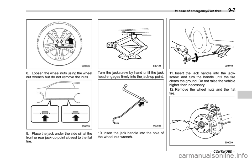
8. Loosen the wheel nuts using the wheel
nut wrench but do not remove the nuts.
9. Place the jack under the side sill at the
front or rear jack-up point closest to the flat
tire.
Turn the jackscrew by hand until the jack
head engages firmly into the jack-up point.
10. Insert the jack handle into the hole of
the wheel nut wrench.
11. Insert the jack handle into the jack-
screw, and turn the handle until the tire
clears the ground. Do not raise the vehicle
higher than necessary.
12. Remove the wheel nuts and the flat
tire.
In case of emergency/Flat tires–CONTINUED –9-7
Page 481 of 610
In case of emergency/Flat tires
13. Before putting the spare tire on, clean
the mounting surface of the wheel and hub
with a cloth.
14. Put on the spare tire. Replace the
wheel nuts. Tighten them by hand.
WARNING
Do not use oil or grease on the
wheel studs or nuts when the spare
tire is installed. This could cause the
nuts to become loose and lead to an
accident.
15. Turn the jack handle counterclockwise
to lower the vehicle.
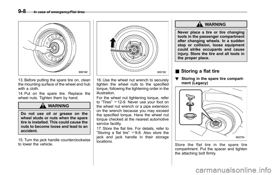
16. Use the wheel nut wrench to securely
tighten the wheel nuts to the specified
torque, following the tightening order in the
illustration.
For the wheel nut tightening torque, refer
to “Tires ”F 12-9. Never use your foot on
the wheel nut wrench or a pipe extension
on the wrench because you may exceed
the specified torque. Have the wheel nut
torque checked at the nearest automotive
service facility.
17. Store the flat tire. For details, refer to
“Storing a flat tire ”F 9-8. Also store the
jack and jack handle in their storage
locations.
WARNING
Never place a tire or tire changing
tools in the passenger compartment
after changing wheels. In a sudden
stop or collision, loose equipment
could strike occupants and cause
injury. Store the tire and all tools in
the proper place.
& Storing a flat tire
! Storing in the spare tire compart-
ment (Legacy)
Store the flat tire in the spare tire
compartment. Put the spacer and tighten
the attaching bolt firmly.
9-8
Page 487 of 610
In case of emergency/Towing
&Towing hook and tie-down
hooks/holes
The towing hook should be used only in
an emergency (e.g., to free a stuck vehicle
from mud, sand or snow).
A towing hook is supplied with Outback
only. Legacy is not supplied with a towing
hook (it is available as an accessory). On
Legacy, the towing access cover is on the
rear bumper only.
SUBARU recommends towing be done
by your SUBARU dealer or a commer-
cial towing service.
CAUTION
. Use only the specified towing
hook and tie-down hooks/holes.
Never use suspension parts or
other parts of the body for towing
or tie-down purposes.
. Never use the tie-down hole clo-
sest to the muffler under the
vehicle for towing purposes.
. To prevent deformation to the
bumper and the towing hook, do
not apply excessive lateral load
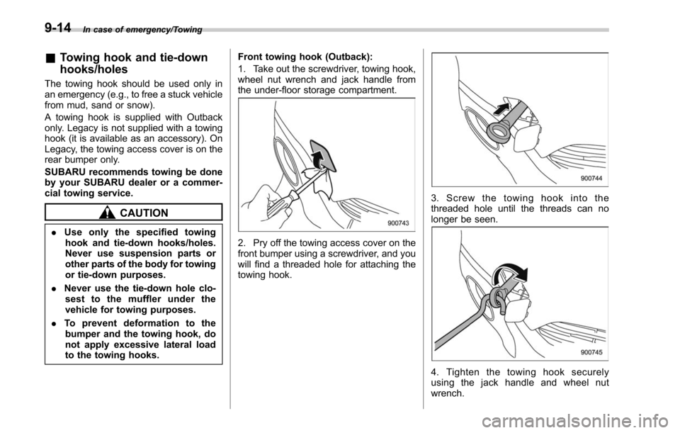
to the towing hooks. Front towing hook (Outback):
1. Take out the screwdriver, towing hook,
wheel nut wrench and jack handle from
the under-floor storage compartment.2. Pry off the towing access cover on the
front bumper using a screwdriver, and you
will find a threaded hole for attaching the
towing hook.
3. Screw the towing hook into the
threaded hole until the threads can no
longer be seen.
4. Tighten the towing hook securely
using the jack handle and wheel nut
wrench.
9-14
Page 488 of 610
After towing, remove the towing hook from
the vehicle and stow it in the under-floor
storage compartment.
Fit the towing hook cover on the bumper.
WARNING
.Do not use the towing hook for
purposes other than towing your
vehicle.
. Be sure to remove the towing
hook after towing. Leaving the
towing hook mounted on the
vehicle could interfere with prop-
er operation of the SRS airbag
system in a frontal collision.
Rear towing hook (Outback):
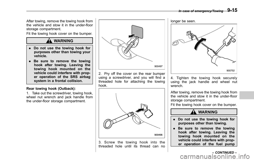
1. Take out the screwdriver, towing hook,
wheel nut wrench and jack handle from
the under-floor storage compartment.
2. Pry off the cover on the rear bumper
using a screwdriver, and you will find a
threaded hole for attaching the towing
hook.
3. Screw the towing hook into the
threaded hole until its thread can no longer be seen.
4. Tighten the towing hook securely
using the jack handle and wheel nut
wrench.
After towing, remove the towing hook from
the vehicle and stow it in the under-floor
storage compartment.
Fit the towing hook cover on the bumper.
WARNING
.
Do not use the towing hook for
purposes other than towing.
. Be sure to remove the towing
hook after towing. Leaving the
towing hook mounted on the
vehicle could interfere with prop-
er operation of the fuel pump
In case of emergency/Towing
–CONTINUED –9-15
Page 489 of 610
In case of emergency/Towing
shut off function when the vehi-
cle is struck from behind.
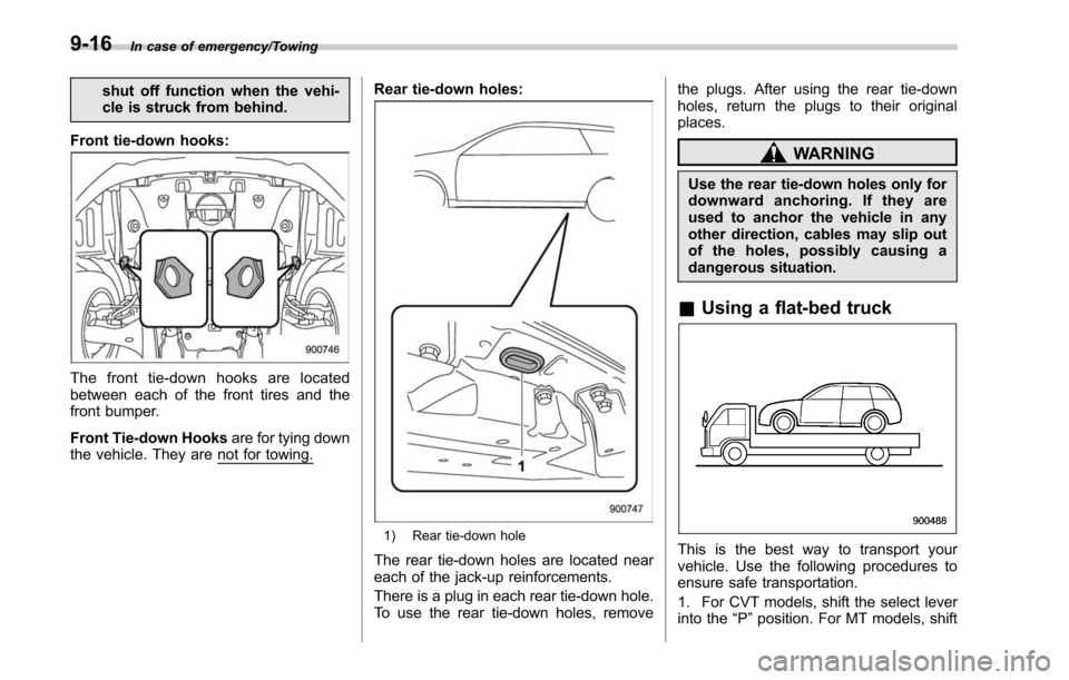
Front tie-down hooks:
The front tie-down hooks are located
between each of the front tires and the
front bumper.
Front Tie-down Hooks are for tying down
the vehicle. They are
not for towing. Rear tie-down holes:
1) Rear tie-down hole
The rear tie-down holes are located near
each of the jack-up reinforcements.
There is a plug in each rear tie-down hole.
To use the rear tie-down holes, remove the plugs. After using the rear tie-down
holes, return the plugs to their original
places.
WARNING
Use the rear tie-down holes only for
downward anchoring. If they are
used to anchor the vehicle in any
other direction, cables may slip out
of the holes, possibly causing a
dangerous situation.
&
Using a flat-bed truck
This is the best way to transport your
vehicle. Use the following procedures to
ensure safe transportation.
1. For CVT models, shift the select lever
into the “P”position. For MT models, shift
9-16
Page 506 of 610
Maintenance schedule
U.S. models
The scheduled maintenance items re-
quired to be serviced at regular intervals
are shown in the“Warranty and Main-
tenance Booklet ”. For details, read the
separate “Warranty and Maintenance
Booklet ”.
Canada models
The scheduled maintenance items re-
quired to be serviced at regular intervals
are shown in the “Warranty and Service
Booklet ”. For details, read the separate
“Warranty and Service Booklet ”.
Except for U.S. and Canada models
Some items of your vehicle are required to
be serviced at scheduled intervals. For
details about your maintenance schedule,
read the separate “Warranty and Main-
tenance Booklet ”.
Maintenance precautions
When maintenance and service are re-
quired, it is recommended that all work be
done by an authorized SUBARU dealer.
If you perform maintenance and service
by yourself, you should familiarize yourself
with the information provided in this
section on general maintenance and
service for your SUBARU.
Incorrect or incomplete service could
cause improper or unsafe vehicle opera-
tion. Any problems caused by improper
maintenance and service performed by
you are not eligible for warranty coverage.
WARNING
.Testing of an All-Wheel Drive
vehicle must NEVER be per-
formed on a single two-wheel
dynamometer or similar appara-
tus. Attempting to do so will
result in transmission damage
and in uncontrolled vehicle
movement and may cause an
accident or injuries to persons
nearby.
. Always select a safe area when
performing maintenance on your
vehicle. .
Always be very careful to avoid
injury when working on the vehi-
cle. Remember that some of the
materials in the vehicle may be
hazardous if improperly used or
handled, for example, battery
acid.
. Your vehicle should only be ser-
viced by persons fully competent
to do so. Serious personal injury
may result to persons not experi-
enced in servicing vehicles.
. Always use the proper tools and
make certain that they are well
maintained.
. Never get under the vehicle sup-
ported only by a jack. Always use
safety stands to support the
vehicle.
. Never keep the engine running in
a poorly ventilated area, such as
a garage or other closed areas.
. Do not smoke or allow open
flames around the fuel or battery.
This will cause a fire.
. Because the fuel system is under
pressure, replacement of the fuel
filter should be performed only
by your SUBARU dealer.
. Wear adequate eye protection to
Maintenance and service/Maintenance schedule
–CONTINUED –11-3
Page 596 of 610
Information display..................................................... 3-33
Inside mirror .............................................................. 3-63
Interior lights ............................................................... 6-2
Internal trunk lid release handle ................................... 2-39
J
Jack-up point ............................................................... 9-5
Jump starting. ............................................................ 9-11
K
Key ........................................................................\
.... 2-3 Number .................................................................. 2-3
Reminder chime. ...................................................... 3-5
Replacement ........................................................... 2-5
Keyless access with push-button start system .. ............. 2-10
Disabling keyless access functions ........................... 2-18
Locking and unlocking doors ................................... 2-14
Opening rear gate .................................................. 2-16
Opening trunk ........................................................ 2-16
Warning chimes and warning indicator ...................... 3-25
When access key does not operate properly ............. 9-18
Keyless entry system ................................................. 2-24
L
LCA ........................................................................\
. 7-55
Leather seat materials ................................................ 10-5
License plate light ..................................................... 11-47
Light Backup ................................................................ 11-46
Cargo area .................................................... 6-3, 11-49
Control switch ........................................................ 3-46 Daytime running
..................................................... 3-53
Dome ............................................................ 6-2, 11-48
Door step ............................................................ 11-49
Front fog ..................................................... 3-56, 11-42
Front side marker ................................................... 3-47
Ignition switch ......................................................... 3-5
License plate ....................................................... 11-47
Map .............................................................. 6-2, 11-48
Rear combination ................................................. 11-44
Rear side marker light ........................................... 11-44
Rear turn signal .................................................... 11-44
Trunk .................................................................. 11-49
Turn signal ........................................ 3-54, 11-42, 11-44
Vanity mirror ........................................................... 6-5
Loading your vehicle ................................................... 8-13
Low fuel warning light ................................................. 3-22
Low tire pressure warning light ..................................... 3-17
Lower and tether anchorage ........................................ 1-36
M
Maintenance Precautions ........................................................... 11-3
Schedule ............................................................... 11-3
Seatbelt. ................................................................ 1-24
Tips ...................................................................... 11-5
Tools ...................................................................... 9-3
Malfunction indicator light (check engine warning light) .... 3-16
Manual Climate control system ............................................. 4-6
Mode (continuously variable transmission) ................. 7-29
Seat .......................................................................
1-4
Index14-7