climate control SUBARU TRIBECA 2008 Owners Manual
[x] Cancel search | Manufacturer: SUBARU, Model Year: 2008, Model line: TRIBECA, Model: SUBARU TRIBECA 2008Pages: 409, PDF Size: 5.75 MB
Page 4 of 409
2Chapter 4: Climate control
This chapter informs you how to operate
the climate control.
Chapter 5: Audio
This chapter informs you how to operate
your audio system.
Chapter 6: Interior equipment
This chapter informs you how to operate
interior equipment.
Chapter 7: Starting and operating
This chapter informs you how to start and
operate your SUBARU.
Chapter 8: Driving tips
This chapter informs you how to drive your
SUBARU in various conditions and ex-
plains some safety tips on driving.
Chapter 9: In case of emergency
This chapter informs you what to do if you
have a problem while driving, such as a
flat tire or engine overheating.
Chapter 10: Appearance care
This chapter informs you how to keep your
SUBARU looking good.
Chapter 11: Maintenance and service
This chapter informs you when you need
to take your SUBARU to the dealer for
scheduled maintenance and informs you
how to keep your SUBARU running
properly.Chapter 12: Specifications
This chapter informs you about dimension
and capacities of your SUBARU.
Chapter 13: Consumer information and
Reporting safety defects
This chapter informs you about Tire
information, Uniform tire quality grading
standards and Reporting safety defects.
Chapter 14: Index
This is an alphabetical listing of all that’
sin
this manual. You can use it to quickly find
something you want to read.
& Safety warningsYou will find a number of WARNINGs,
CAUTIONs and NOTEs in this manual.
These safety warnings alert you to poten-
tial hazards that could result in injury to
you or others.
Please read these safety warnings as well
as all other portions of this manual care-
fully in order to gain a better understand-
ing of how to use your SUBARU vehicle
safely.
WARNING
A WARNING indicates a situation in
which serious injury or death could
result if the warning is ignored.
CAUTION
A CAUTION indicates a situation in
which injury or damage to your
vehicle, or both, could result if the
caution is ignored.NOTEA NOTE gives information or sugges-
tions how to make better use of your
vehicle.&Safety symbolYou will find a circle with a slash through it
in this manual. This symbol means “Do
not ”,“Do not do this ”,or“Do not let this
happen ”, depending upon the context.
ProCarManuals.com
Page 11 of 409
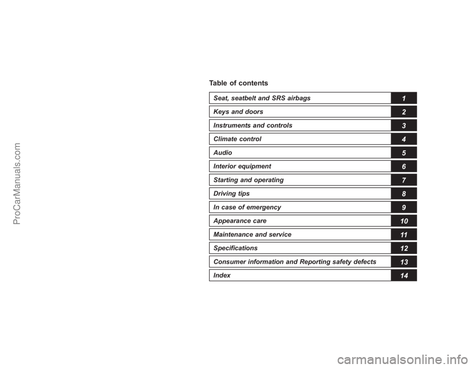
Table of contentsSeat, seatbelt and SRS airbags
1
Keys and doors
2
Instruments and controlsClimate control
4
Audio
5
Interior equipment
6
Starting and operating
7
Driving tips
8
In case of emergency
9
Appearance care
10
Maintenance and service
11
Specifications
12
Consumer information and Reporting safety defects
13
Index
143
ProCarManuals.com
Page 16 of 409
14
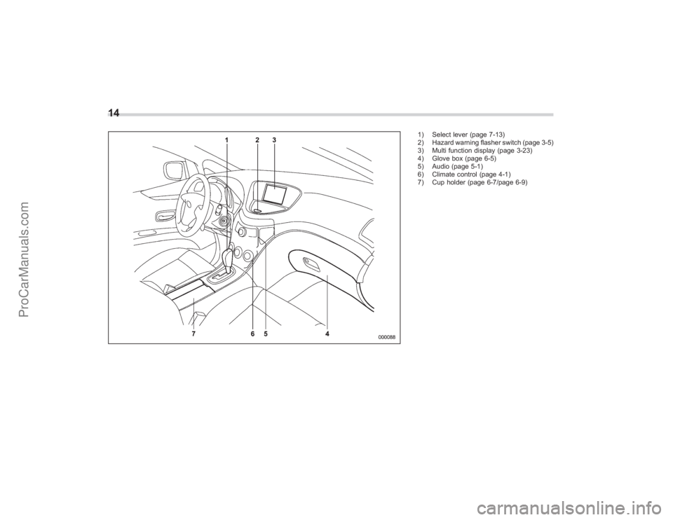
1) Select lever (page 7-13)
2) Hazard warning flasher switch (page 3-5)
3) Multi function display (page 3-23)
4) Glove box (page 6-5)
5) Audio (page 5-1)
6) Climate control (page 4-1)
7) Cup holder (page 6-7/page 6-9)
ProCarManuals.com
Page 157 of 409
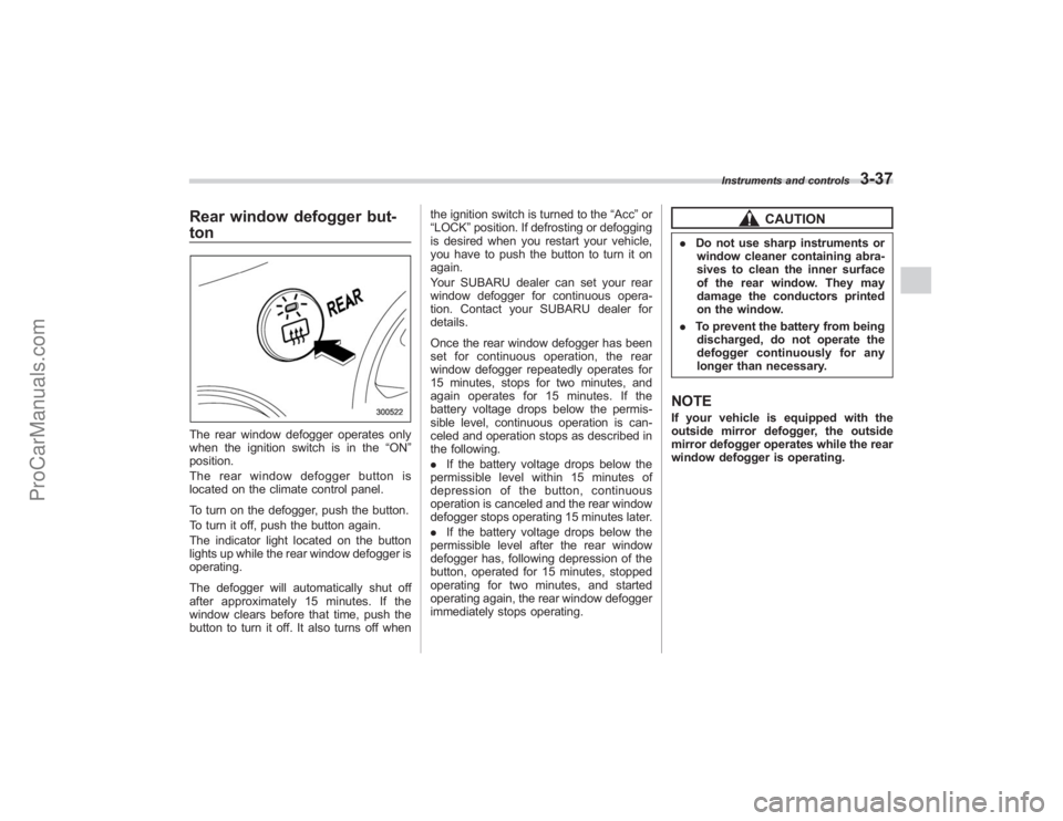
Rear window defogger but-
tonThe rear window defogger operates only
when the ignition switch is in the“ON”
position.
The rear window defogger button is
located on the climate control panel.
To turn on the defogger, push the button.
To turn it off, push the button again.
The indicator light located on the button
lights up while the rear window defogger is
operating.
The defogger will automatically shut off
after approximately 15 minutes. If the
window clears before that time, push the
button to turn it off. It also turns off when the ignition switch is turned to the
“Acc ”or
“LOCK” position. If defrosting or defogging
is desired when you restart your vehicle,
you have to push the button to turn it on
again.
Your SUBARU dealer can set your rear
window defogger for continuous opera-
tion. Contact your SUBARU dealer for
details.
Once the rear window defogger has been
set for continuous operation, the rear
window defogger repeatedly operates for
15 minutes, stops for two minutes, and
again operates for 15 minutes. If the
battery voltage drops below the permis-
sible level, continuous operation is can-
celed and operation stops as described in
the following.
. If the battery voltage drops below the
permissible level within 15 minutes of
depression of the button, continuous
operation is canceled and the rear window
defogger stops operating 15 minutes later.
. If the battery voltage drops below the
permissible level after the rear window
defogger has, following depression of the
button, operated for 15 minutes, stopped
operating for two minutes, and started
operating again, the rear window defogger
immediately stops operating.
CAUTION
. Do not use sharp instruments or
window cleaner containing abra-
sives to clean the inner surface
of the rear window. They may
damage the conductors printed
on the window.
. To prevent the battery from being
discharged, do not operate the
defogger continuously for any
longer than necessary.NOTEIf your vehicle is equipped with the
outside mirror defogger, the outside
mirror defogger operates while the rear
window defogger is operating.
Instruments and controls
3-37
ProCarManuals.com
Page 163 of 409
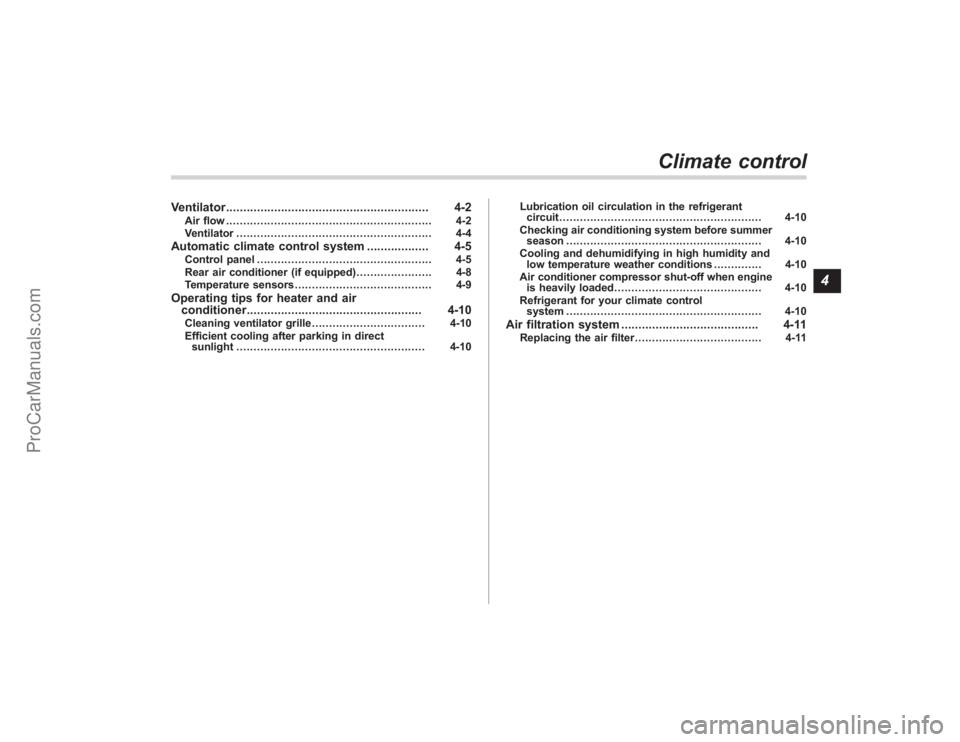
Ventilator........................................................... 4-2
Air flow............................................................ 4-2
Ventilator ......................................................... 4-4
Automatic climate control system .................. 4-5
Control panel................................................... 4-5
Rear air conditioner (if equipped) ...................... 4-8
Temperature sensors ........................................ 4-9
Operating tips for heater and air
conditioner ................................................... 4-10
Cleaning ventilator grille ................................. 4-10
Efficient cooling after parking in direct sunlight ....................................................... 4-10 Lubrication oil circulation in the refrigerant
circuit ........................................................... 4-10
Checking air conditioning system before summer season ......................................................... 4-10
Cooling and dehumidifying in high humidity and low temperature weather conditions .............. 4-10
Air conditioner compressor shut-off when engine is heavily loaded ........................................... 4-10
Refrigerant for your climate control system ......................................................... 4-10
Air filtration system ........................................ 4-11
Replacing the air filter ..................................... 4-11
Climate control
4
ProCarManuals.com
Page 164 of 409
4-2
Climate control
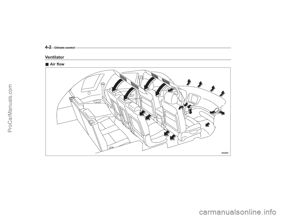
Ventilator&Air flow
ProCarManuals.com
Page 165 of 409
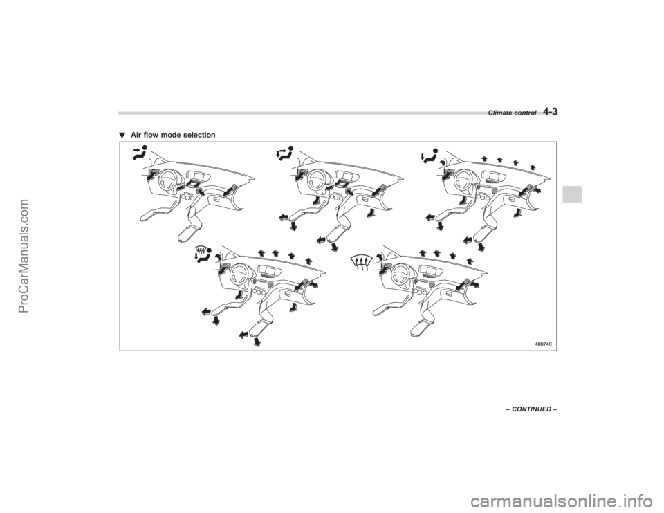
!Air flow mode selection
Climate control
4-3
–CONTINUED –
ProCarManuals.com
Page 166 of 409
4-4
Climate control
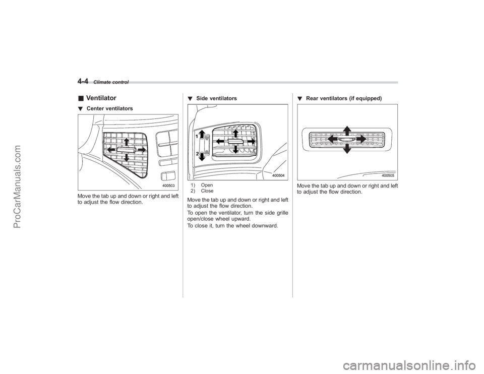
&Ventilator! Center ventilatorsMove the tab up and down or right and left
to adjust the flow direction. !
Side ventilators
1) Open
2) CloseMove the tab up and down or right and left
to adjust the flow direction.
To open the ventilator, turn the side grille
open/close wheel upward.
To close it, turn the wheel downward. !
Rear ventilators (if equipped)
Move the tab up and down or right and left
to adjust the flow direction.
ProCarManuals.com
Page 167 of 409
Automatic climate control
systemNOTE.Operate the automatic climate con-
trol system when the engine is running.
. The blower fan rotates at a low
speed when the engine coolant tem-
perature is low.
For efficient defogging or dehumidify-
ing in cold weather, press the “A/C ”
button.
. Even when cooling is not necessary,
setting the temperature much lower
than the current outlet air temperature
turns on the air conditioner compres-
sor automatically and the “A/C ”indi-
cator light on the control panel comes
on.
. Seven-seater models each have a
rear air conditioner. The fan speed of
the rear air conditioner can be ad-
justed, but other adjustments (outlet
air temperature, air distribution, etc.)
are not possible for the rear air condi-
tioner. For details, refer to “Rear air
conditioner ”in this section.
The automatic climate control system
automatically controls outlet air tempera-
ture, fan speed, air flow distribution air-
inlet control, and air conditioner compres- sor operation. It activates when the
“AUTO
”button is pressed, and is used to
maintain a constant, comfortable climate
within the passenger compartment.
The temperature can be set within a range
of 65 to 85 8F (18 to 32 8C).
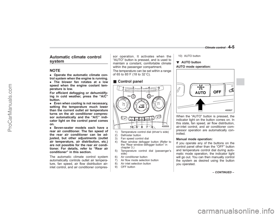
& Control panel1) Temperature control dial (driver ’s side)
2) Defroster button
3) Fan speed control dial
4) Rear window defogger button (Refer to the“Rear window defogger button ”in
chapter 3.)
5) Temperature control dial (passenger ’s
side)
6) Air conditioner button
7) Air flow mode selection button
8) Air inlet selection button
9) OFF button 10) AUTO button
!
AUTO button
AUTO mode operation:When the “AUTO”button is pressed, the
indicator light on the button comes on. In
this state, fan speed, air flow distribution,
air-inlet control, and air conditioner com-
pressor operation are automatically con-
trolled.
Manual mode operation:
If you operate any of the buttons on the
control panel other than the “OFF”button
and temperature control dial during auto-
matic mode operation, the indicator light
will go out. You can then manually control
the system as desired using the button
you operated.
Climate control
4-5
– CONTINUED –
ProCarManuals.com
Page 168 of 409
4-6
Climate control
To change the system back to the AUTO
mode, press the“AUTO”button.
! OFF buttonThe Automatic Climate Control system
turns off (the air conditioner compressor
and fan turn off) when the “OFF”button is
pressed.
When the “OFF”button is pressed, the
outside air introduction mode (air inlet
selection OFF) is automatically selected. !
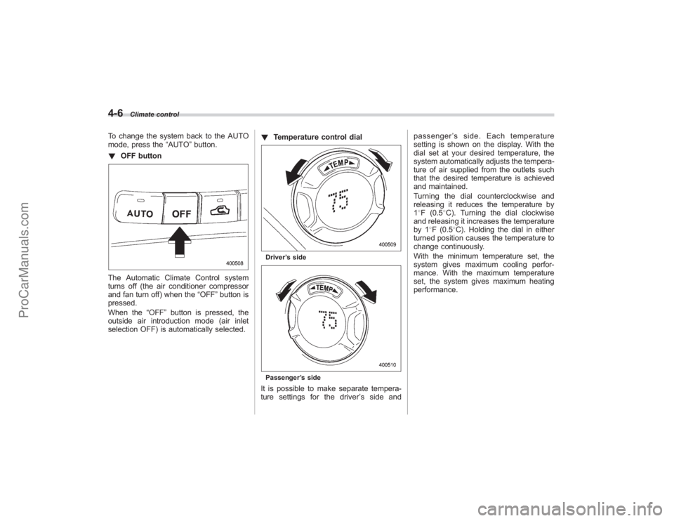
Temperature control dial
Driver ’s sidePassenger ’s sideIt is possible to make separate tempera-
ture settings for the driver ’ssideand passenger
’s side. Each temperature
setting is shown on the display. With the
dial set at your desired temperature, the
system automatically adjusts the tempera-
ture of air supplied from the outlets such
that the desired temperature is achieved
and maintained.
Turning the dial counterclockwise and
releasing it reduces the temperature by
1 8F (0.5 8C). Turning the dial clockwise
and releasing it increases the temperature
by 1 8F (0.5 8C). Holding the dial in either
turned position causes the temperature to
change continuously.
With the minimum temperature set, the
system gives maximum cooling perfor-
mance. With the maximum temperature
set, the system gives maximum heating
performance.
ProCarManuals.com