key SUBARU TRIBECA 2009 1.G Service Workshop Manual
[x] Cancel search | Manufacturer: SUBARU, Model Year: 2009, Model line: TRIBECA, Model: SUBARU TRIBECA 2009 1.GPages: 2453, PDF Size: 46.32 MB
Page 2259 of 2453
CS-7
AT Shift Lock Control System
CONTROL SYSTEMS
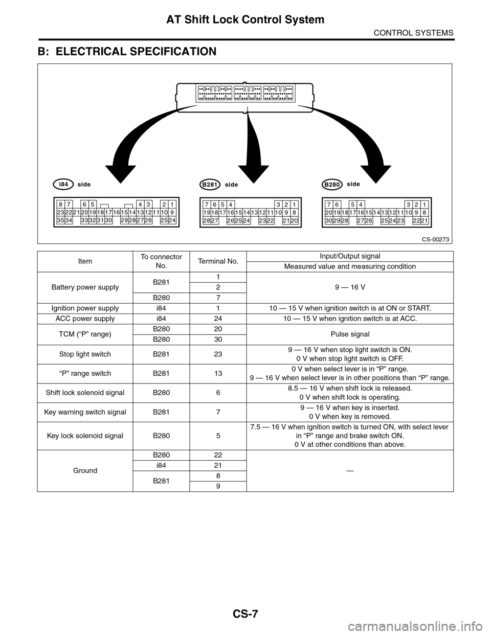
B: ELECTRICAL SPECIFICATION
ItemTo c o n n e c t o r
No.Te r m i n a l N o .Input/Output signal
Measured value and measuring condition
Battery power supplyB2811
9 — 16 V2
B280 7
Ignition power supply i84 1 10 — 15 V when ignition switch is at ON or START.
ACC power supply i84 24 10 — 15 V when ignition switch is at ACC.
TCM (“P” range)B280 20Pulse signalB280 30
Stop light switch B281 239 — 16 V when stop light switch is ON.
0 V when stop light switch is OFF.
“P” range switch B281 130 V when select lever is in “P” range.
9 — 16 V when select lever is in other positions than “P” range.
Shift lock solenoid signal B280 68.5 — 16 V when shift lock is released.
0 V when shift lock is operating.
Key war ning switch signal B281 79 — 16 V when key is inserted.
0 V when key is removed.
Key lock solenoid signal B280 5
7.5 — 16 V when ignition switch is turned ON, with select lever
in “P” range and brake switch ON.
0 V at other conditions than above.
Ground
B280 22
—i84 21
B2818
9
CS-00273
71928
61827
51741626152514241312231122
3102921
1820
B281side
72030
619291828
51741627152614132512241123
3102922
1821
B280side
82335
722342162033
51932183117301615291428
41327
312261121025
1924
i84side
Page 2260 of 2453
CS-8
AT Shift Lock Control System
CONTROL SYSTEMS
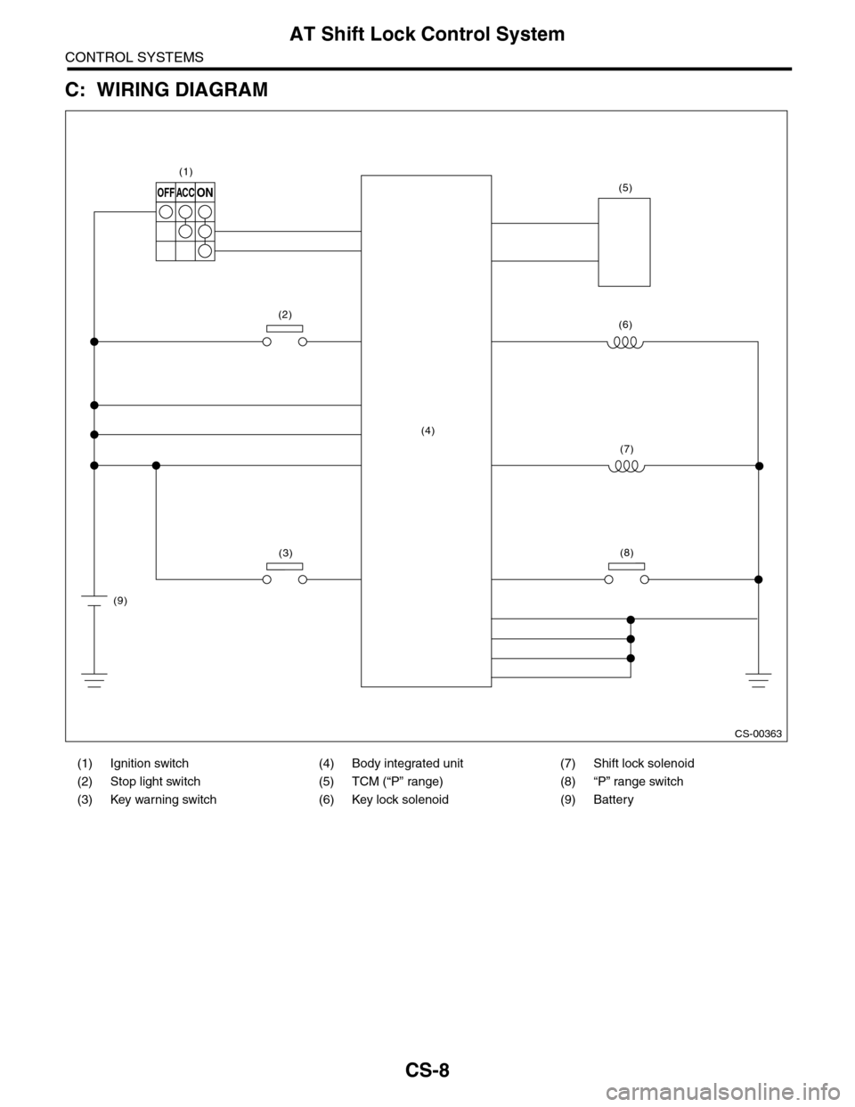
C: WIRING DIAGRAM
(1) Ignition switch (4) Body integrated unit (7) Shift lock solenoid
(2) Stop light switch (5) TCM (“P” range) (8) “P” range switch
(3) Key warning switch (6) Key lock solenoid (9) Battery
CS-00363
OFFACCON
(1)
(2)
(3)
(4)
(9)
(6)
(7)
(8)
(5)
Page 2261 of 2453
CS-9
AT Shift Lock Control System
CONTROL SYSTEMS
D: INSPECTION
1. SHIFT LOCK OPERATION
Step Check Yes No
1CHECK SHIFT LOCK.
1) Turn the ignition switch to ON.
2) Shift the select lever to “P” range.
While brake pedal is not
depressed, is it possible to
move the select lever from the
“P” range to other ranges?
Inspect “SELECT
LEVER CANNOT
BE SHIFT
LOCKED”.
LEVER CANNOT
BE SHIFTED,
INSPECTION, AT
Shift Lock Control
System.>
Go to step 2.
2CHECK SHIFT LOCK.While brake pedal is
depressed, is it possible to
move the select lever from the
“P” range to other ranges?
Go to step 3.Inspect “SELECT
LEVER SHIFT
LOCK CANNOT
BE RELEASED”.
SELECT LEVER
CANNOT BE
RELEASED.,
INSPECTION, AT
Shift Lock Control
System.>
3CHECK KEY INTERLOCK.Can the ignition switch be
turned to the “LOCK” position
when the select lever is set to
other than “P” range?
Go to step 4.Go to step 5.
4CHECK BACKUP POWER SUPPLY.
Inspect the backup power supply circuit.
SUPPLY AND GROUND CIRCUIT, INSPEC-
TION, AT Shift Lock Control System.>
Is the backup power supply cir-
cuit operating properly?
Inspect for “KEY
INTERLOCK
CANNOT BE
LOCKED OR
RELEASED”.
SELECT LEVER
CANNOT BE
RELEASED.,
INSPECTION, AT
Shift Lock Control
System.>
Repair the backup
power supply cir-
cuit.
5CHECK KEY INTERLOCK.Can the ignition switch be
turned to the LOCK position
when the select lever is set to
the “P” range?
AT s h i f t l o c k s y s -
tem is normal.
Inspect for “KEY
INTERLOCK
CANNOT BE
LOCKED OR
RELEASED”.
SELECT LEVER
CANNOT BE
RELEASED.,
INSPECTION, AT
Shift Lock Control
System.>
Page 2268 of 2453
CS-16
AT Shift Lock Control System
CONTROL SYSTEMS
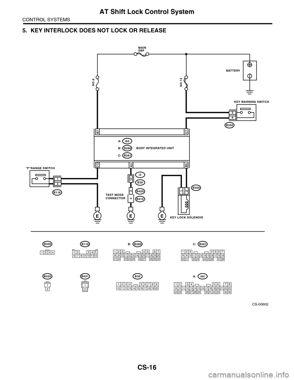
5. KEY INTERLOCK DOES NOT LOCK OR RELEASE
CS-00602
E
B116
5467821931022 231112131415242526 2716171828 29192021 30
B280B:
NO.14
EE
B281C:
B280B:
i84A:
C7B7
B5
12
C13A3
B1162
212
1
2
B350
B350
i3
B38
B420
B410
3
4
BATTERY
KEY WARNING SWITCH
BODY INTEGRATED UNIT
"P"RANGE SWITCH
KEY LOCK SOLENOID
TEST MODECONNECTOR
1234
B350
567821943102422 23 25111213141526 27281617181920 21
B281C:
i84A:
123456789101112
NO.8
MAINSBF
B420
12
B421
12
B38
1234 5678910 11 12 13 16 17 18 19 2014151234567891011121415161718192021222324252627282930313233343513
Page 2269 of 2453
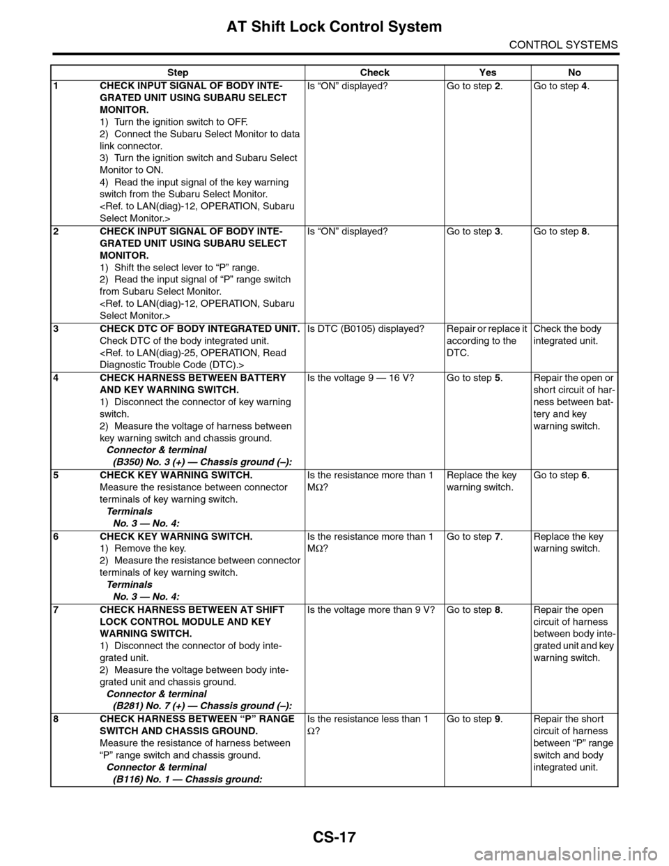
CS-17
AT Shift Lock Control System
CONTROL SYSTEMS
Step Check Yes No
1CHECK INPUT SIGNAL OF BODY INTE-
GRATED UNIT USING SUBARU SELECT
MONITOR.
1) Turn the ignition switch to OFF.
2) Connect the Subaru Select Monitor to data
link connector.
3) Turn the ignition switch and Subaru Select
Monitor to ON.
4) Read the input signal of the key warning
switch from the Subaru Select Monitor.
Is “ON” displayed? Go to step 2.Go to step 4.
2CHECK INPUT SIGNAL OF BODY INTE-
GRATED UNIT USING SUBARU SELECT
MONITOR.
1) Shift the select lever to “P” range.
2) Read the input signal of “P” range switch
from Subaru Select Monitor.
Is “ON” displayed? Go to step 3.Go to step 8.
3CHECK DTC OF BODY INTEGRATED UNIT.
Check DTC of the body integrated unit.
Is DTC (B0105) displayed? Repair or replace it
according to the
DTC.
Check the body
integrated unit.
4CHECK HARNESS BETWEEN BATTERY
AND KEY WARNING SWITCH.
1) Disconnect the connector of key warning
switch.
2) Measure the voltage of harness between
key warning switch and chassis ground.
Connector & terminal
(B350) No. 3 (+) — Chassis ground (–):
Is the voltage 9 — 16 V? Go to step 5.Repair the open or
short circuit of har-
ness between bat-
tery and key
warning switch.
5 CHECK KEY WARNING SWITCH.
Measure the resistance between connector
terminals of key warning switch.
Te r m i n a l s
No. 3 — No. 4:
Is the resistance more than 1
MΩ?
Replace the key
warning switch.
Go to step 6.
6 CHECK KEY WARNING SWITCH.
1) Remove the key.
2) Measure the resistance between connector
terminals of key warning switch.
Te r m i n a l s
No. 3 — No. 4:
Is the resistance more than 1
MΩ?
Go to step 7.Replace the key
warning switch.
7CHECK HARNESS BETWEEN AT SHIFT
LOCK CONTROL MODULE AND KEY
WARNING SWITCH.
1) Disconnect the connector of body inte-
grated unit.
2) Measure the voltage between body inte-
grated unit and chassis ground.
Connector & terminal
(B281) No. 7 (+) — Chassis ground (–):
Is the voltage more than 9 V? Go to step 8.Repair the open
circuit of harness
between body inte-
grated unit and key
warning switch.
8CHECK HARNESS BETWEEN “P” RANGE
SWITCH AND CHASSIS GROUND.
Measure the resistance of harness between
“P” range switch and chassis ground.
Connector & terminal
(B116) No. 1 — Chassis ground:
Is the resistance less than 1
Ω?
Go to step 9.Repair the short
circuit of harness
between “P” range
switch and body
integrated unit.
Page 2270 of 2453
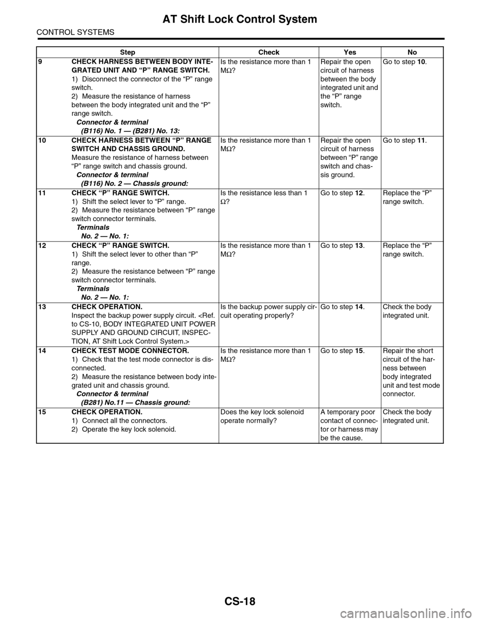
CS-18
AT Shift Lock Control System
CONTROL SYSTEMS
9CHECK HARNESS BETWEEN BODY INTE-
GRATED UNIT AND “P” RANGE SWITCH.
1) Disconnect the connector of the “P” range
switch.
2) Measure the resistance of harness
between the body integrated unit and the “P”
range switch.
Connector & terminal
(B116) No. 1 — (B281) No. 13:
Is the resistance more than 1
MΩ?
Repair the open
circuit of harness
between the body
integrated unit and
the “P” range
switch.
Go to step 10.
10 CHECK HARNESS BETWEEN “P” RANGE
SWITCH AND CHASSIS GROUND.
Measure the resistance of harness between
“P” range switch and chassis ground.
Connector & terminal
(B116) No. 2 — Chassis ground:
Is the resistance more than 1
MΩ?
Repair the open
circuit of harness
between “P” range
switch and chas-
sis ground.
Go to step 11.
11 CHECK “P” RANGE SWITCH.
1) Shift the select lever to “P” range.
2) Measure the resistance between “P” range
switch connector terminals.
Te r m i n a l s
No. 2 — No. 1:
Is the resistance less than 1
Ω?
Go to step 12.Replace the “P”
range switch.
12 CHECK “P” RANGE SWITCH.
1) Shift the select lever to other than “P”
range.
2) Measure the resistance between “P” range
switch connector terminals.
Te r m i n a l s
No. 2 — No. 1:
Is the resistance more than 1
MΩ?
Go to step 13.Replace the “P”
range switch.
13 CHECK OPERATION.
Inspect the backup power supply circuit.
SUPPLY AND GROUND CIRCUIT, INSPEC-
TION, AT Shift Lock Control System.>
Is the backup power supply cir-
cuit operating properly?
Go to step 14.Check the body
integrated unit.
14 CHECK TEST MODE CONNECTOR.
1) Check that the test mode connector is dis-
connected.
2) Measure the resistance between body inte-
grated unit and chassis ground.
Connector & terminal
(B281) No.11 — Chassis ground:
Is the resistance more than 1
MΩ?
Go to step 15.Repair the short
circuit of the har-
ness between
body integrated
unit and test mode
connector.
15 CHECK OPERATION.
1) Connect all the connectors.
2) Operate the key lock solenoid.
Does the key lock solenoid
operate normally?
A temporary poor
contact of connec-
tor or harness may
be the cause.
Check the body
integrated unit.
Step Check Yes No
Page 2292 of 2453
WI-8
Basic Diagnostic Procedure
WIRING SYSTEM
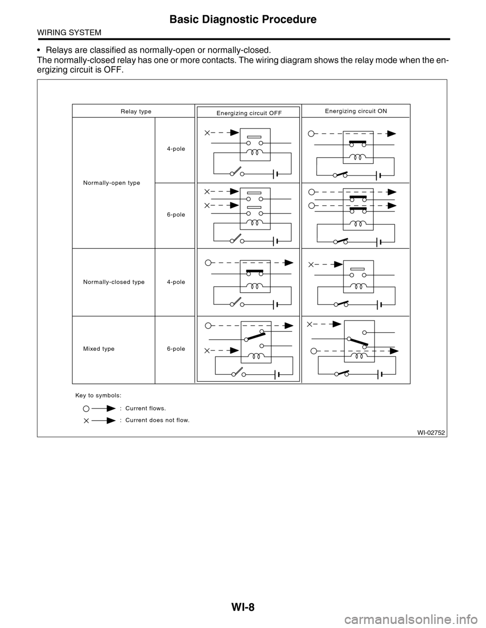
•Relays are classified as normally-open or normally-closed.
The normally-closed relay has one or more contacts. The wiring diagram shows the relay mode when the en-
ergizing circuit is OFF.
Relay type
4-pole
6-pole
4-pole
6-pole
Normally-open type
Normally-closed type
Mixed type
Key to symbols:
: Current flows.
: Current does not flow.
Energizing circuit OFFEnergizing circuit ON
WI-02752
Page 2304 of 2453
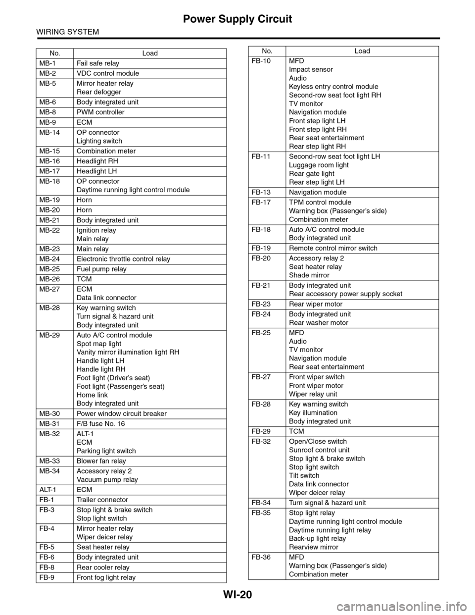
WI-20
Power Supply Circuit
WIRING SYSTEM
No. Load
MB-1 Fail safe relay
MB-2 VDC control module
MB-5 Mirror heater relay
Rear defogger
MB-6 Body integrated unit
MB-8 PWM controller
MB-9 ECM
MB-14 OP connector
Lighting switch
MB-15 Combination meter
MB-16 Headlight RH
MB-17 Headlight LH
MB-18 OP connector
Daytime running light control module
MB-19 Horn
MB-20 Horn
MB-21 Body integrated unit
MB-22 Ignition relay
Main relay
MB-23 Main relay
MB-24 Electronic throttle control relay
MB-25 Fuel pump relay
MB-26 TCM
MB-27 ECM
Data link connector
MB-28 Key warning switch
Tu r n s i g n a l & h a z a r d u n i t
Body integrated unit
MB-29 Auto A/C control module
Spot map light
Va n i t y m i r r o r i l l u m i n a t i o n l i g h t R H
Handle light LH
Handle light RH
Foot light (Driver’s seat)
Foot light (Passenger’s seat)
Home link
Body integrated unit
MB-30 Power window circuit breaker
MB-31 F/B fuse No. 16
MB-32 ALT-1
ECM
Par king light switch
MB-33 Blower fan relay
MB-34 Accessory relay 2
Va c u u m p u m p r e l ay
ALT-1 ECM
FB-1 Trailer connector
FB-3 Stop light & brake switch
Stop light switch
FB-4 Mirror heater relay
Wiper deicer relay
FB-5 Seat heater relay
FB-6 Body integrated unit
FB-8 Rear cooler relay
FB-9 Front fog light relay
FB-10 MFD
Impact sensor
Audio
Keyless entr y control module
Second-row seat foot light RH
TV monitor
Navigation module
Fr o n t s te p li gh t LH
Fr o n t s te p li gh t RH
Rear seat entertainment
Rear step light RH
FB-11 Second-row seat foot light LH
Luggage room light
Rear gate light
Rear step light LH
FB-13 Navigation module
FB-17 TPM control module
War ning box (Passenger’s side)
Combination meter
FB-18 Auto A/C control module
Body integrated unit
FB-19 Remote control mirror switch
FB-20 Accessory relay 2
Seat heater relay
Shade mirror
FB-21 Body integrated unit
Rear accessory power supply socket
FB-23 Rear wiper motor
FB-24 Body integrated unit
Rear washer motor
FB-25 MFD
Audio
TV monitor
Navigation module
Rear seat entertainment
FB-27 Front wiper switch
Fr o n t wi p er mo t or
Wiper relay unit
FB-28 Key warning switch
Key illumination
Body integrated unit
FB-29 TCM
FB-32 Open/Close switch
Sunroof control unit
Stop light & brake switch
Stop light switch
Tilt switch
Data link connector
Wiper deicer relay
FB-34 Turn signal & hazard unit
FB-35 Stop light relay
Daytime running light control module
Daytime running light relay
Back-up light relay
Rearview mirror
FB-36 MFD
War ning box (Passenger’s side)
Combination meter
No. Load
Page 2306 of 2453
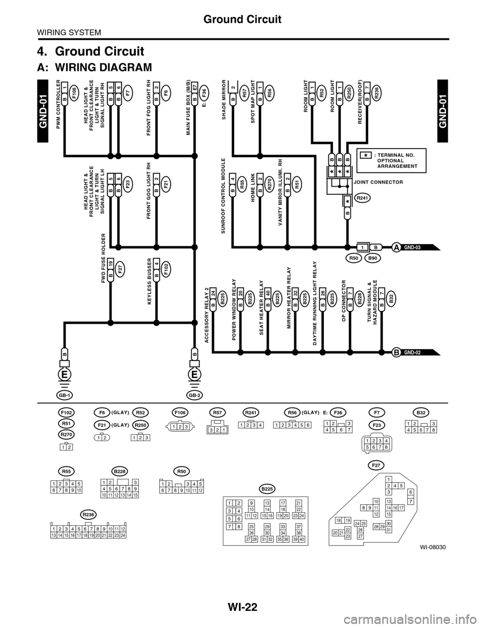
WI-22
Ground Circuit
WIRING SYSTEM
4. Ground Circuit
A: WIRING DIAGRAM
WI-08030
GND-01GND-01
F106B1
PWM CONTROLLER
F6(GLAY)(GLAY)
(GLAY)
F102
R270
F21
F7F6B2
FRONT FOG LIGHT RH
E:
F36B E7
MAIN FUSE BOX (M/B)
R55B4R51B2
VANITY MIROR ILLUMI. RH
R270B2
HOME LINK
R52B1
1
ROOM LIGHT
R250R57B1
ROOM LIGHT
R236B7
RECEIVER(ROOF)SHADE MIRROR
B225B 26
DAYTIME RUNNING LIGHT RELAY
F27B 19FWD FUSE HOLDER
F102B4
KEYLESS BUSSERB225B 24
ACCESSORY RELAY 2
B225B 40
SEAT HEATER RELAY
B225B 20
POWER WINDOW RELAY
B228B7
OP CONNECTOR
B32B7
TURN SIGNAL &HAZARD MODULE
B225B 32
MIRROR HEATER RELAY
GND-02B
GB-1
B
GB-2
B
B
12
12
R52
R250
123
F7
F23
R57
B228
131415
123456789101112
F27
13141516 17
27
24 252620 212223
29303128
89101112
12534
7
6
1918
B225
13141516
17
27
24
2526
20
212223
293031283235
33343738393640
8
9101112
12
534
761918
B32
12345678
SUNROOF CONTROL MODULE
HEAD LIGHT &FRONT CLEARANCELIGHT & TURNSIGNAL LIGHT RH
GND-03A
R51
234510 111678912
R50
F106
123
B A16B5B6
F23F21B2
FRONT GOG LIGHT RH
HEAD LIGHT &FRONT CLEARANCELIGHT & TURNSIGNAL LIGHT LH
B A16B5B6
R56B
SPOT MAP LIGHT
JOINT CONNECTOR
R241
***
*
B90R50
B
B
BBB
1
*: TERMINAL NO. OPTIONAL ARRANGEMENT
123
R56
1234561234567
F36E:
R55
12346789510
R241
1234
R236
123 8910413 14 15 1656711121718192021222324
2
34561278
Page 2307 of 2453
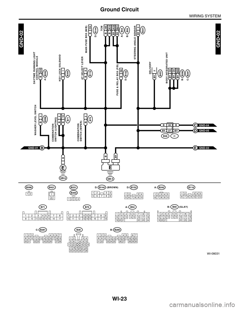
WI-23
Ground Circuit
WIRING SYSTEM
WI-08031
GND-02GND-02
GB-6
B28
BY
B
BY 27
GND-01B
B
GB-4
BYB
B144B
MAIN FUSE BOX (M/B)
A:
B116B4AT SELECT LEVER
B54
A:
B242
B:
B:C:D:
B55B A5B A14BY A19BY B21TCMB231BY 3
STEERING ANGLE SENSOR
B350B1KEY LOCK SOLENOID
B152B D8
FUSE & RELAY BOX (F/B)
B421BY
DELIVERY
B71B2B 16
COMBINATIONSWITCH (LIGHTING)
B70B2
COMBINATIONSWITCH (WIPER)
B396B2
WASHER LEVEL SWITCH
GND-04C
GND-05D
B280B281BY C8BY C9BY B22
BODY INTEGRATED UNIT
GND-03E
B36i1
D4
D:
B231
B350
1234
B152
12345678910
B70
2364571891112151314 1610 1718
A:B54
A:B242
B:B55
123410 11 1219 20 21135614 1578916 17 1822 23 24
12 7 8 9563410 11 1219 20 2113 14 15 16 17 1822 23 24
567821943102422 23 25111213141526 27 281617181920 21
B281C:
5467821931022 23111213141524 25 26 2716171828 29192021 30
B280B:B36
56782194310
242223 252726 28
11121314151617181920 21
(GLAY)
D:
B71
23456718910 11 12 13 14 15 16 17
B A10
DAYTIME RUNNING LIGHT
CONTROL MODULE
12346789510
B116
123456789101112
B396
1212
B421(BROWN)B144D:
157628349
2