steering wheel SUBARU TRIBECA 2009 1.G Service User Guide
[x] Cancel search | Manufacturer: SUBARU, Model Year: 2009, Model line: TRIBECA, Model: SUBARU TRIBECA 2009 1.GPages: 2453, PDF Size: 46.32 MB
Page 746 of 2453
BR-32
Air Bleeding
BRAKE
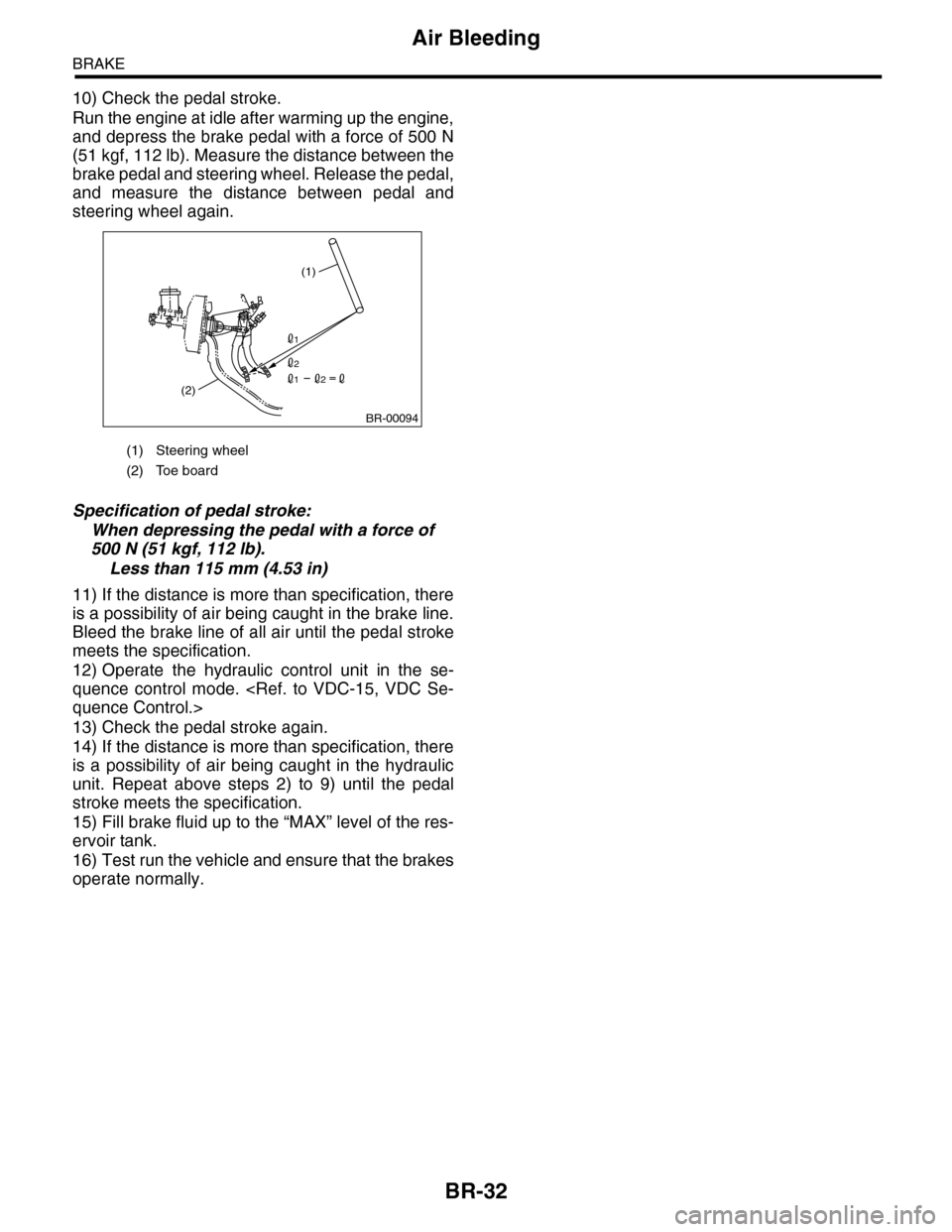
10) Check the pedal stroke.
Run the engine at idle after warming up the engine,
and depress the brake pedal with a force of 500 N
(51 kgf, 112 lb). Measure the distance between the
brake pedal and steering wheel. Release the pedal,
and measure the distance between pedal and
steering wheel again.
Specification of pedal stroke:
When depressing the pedal with a force of
500 N (51 kgf, 112 lb).
Less than 115 mm (4.53 in)
11) If the distance is more than specification, there
is a possibility of air being caught in the brake line.
Bleed the brake line of all air until the pedal stroke
meets the specification.
12) Operate the hydraulic control unit in the se-
quence control mode.
13) Check the pedal stroke again.
14) If the distance is more than specification, there
is a possibility of air being caught in the hydraulic
unit. Repeat above steps 2) to 9) until the pedal
stroke meets the specification.
15) Fill brake fluid up to the “MAX” level of the res-
ervoir tank.
16) Test run the vehicle and ensure that the brakes
operate normally.
(1) Steering wheel
(2) Toe board
(1)
(2)
BR-00094
1
2
21
Page 850 of 2453
FS-2
General Description
FRONT SUSPENSION
1. General Description
A: SPECIFICATION
NOTE:
•Front and rear toe–in and front camber can be adjusted. Adjust if the toe–in or camber tolerance exceeds
specifications.
•Other items indicated in the specifications table cannot be adjusted. If other items exceed specifications,
check the suspension parts and connections for deformation, and replace with new ones as required.
Fr o nt
Wheel arch height
442 (17.4)[Tolerance: +12 mm –24 mm
( +0.47 in –0.94 in)]
mm (in)
Camber (Tolerance: Differences between RH
and LH: 45′ or less)0°00′
Caster (Referential Value) 4°04′
Steering angle (Tolerance: ±1.5°)Inner wheel 37.0°
Outer wheel 32.0°
To e – i n m m ( i n ) 0±3 (0±0.12) Toe angle (sum of both wheels): 0°±0°14′
Kingpin angle (Referential Value) 12°12′
Diameter of stabilizer mm (in) 25 (0.98)
Rear
Wheel arch height
439 (17.3)[Tolerance: +12 mm – 24 mm
( +0.47 in – 0.94 in)]
mm (in)
Camber (Tolerance: Differences between RH
and LH: 45′ or less)–0°31′
To e – i n m m ( i n ) 2±2 (0.08±0.08) Toe angle (sum of both wheels): 0°±0°14′
Thrust angle (Tolerance: ±0°30′)0°
Diameter of stabilizer mm (in) 16 (0.63)
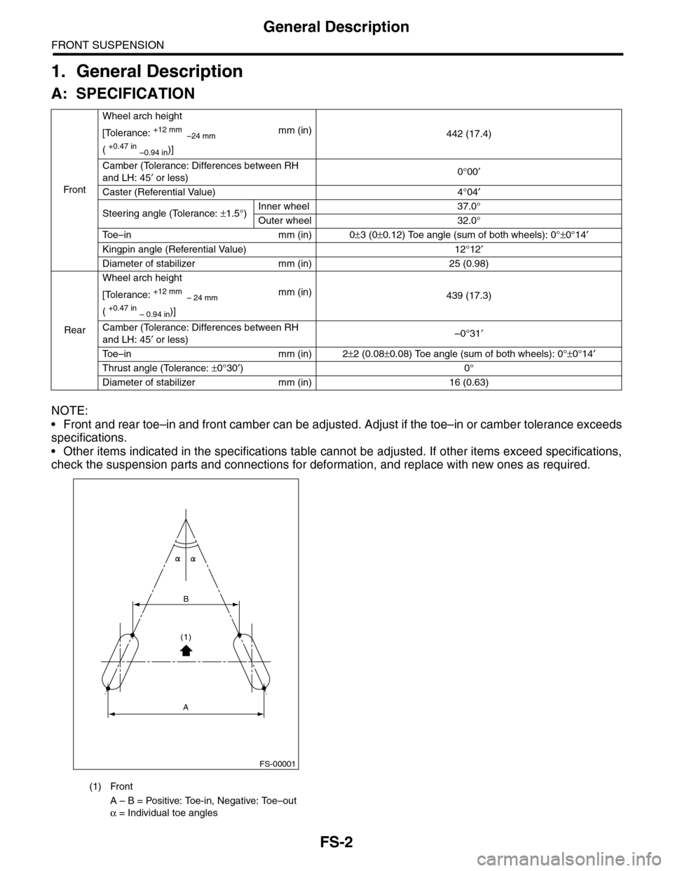
(1) Front
A – B = Positive: Toe-in, Negative: Toe–out
α = Individual toe angles
FS-00001
B
A
(1)
Page 854 of 2453
FS-6
Wheel Alignment
FRONT SUSPENSION
2. Wheel Alignment
A: INSPECTION
Check the following items before performing the wheel alignment measurement.
Check items before measuring wheel alignment:
•Tire inflation pressure
•Uneven wear of RH and LH tires, or difference of sizes
•Tire runout
•Excessive play and wear of ball joint
•Excessive play and wear of tie rod end
•Excessive play of wheel bearing
•Right and left wheel base imbalance
•Deformation and excessive play of steering link
•Deformation and excessive play of suspension parts
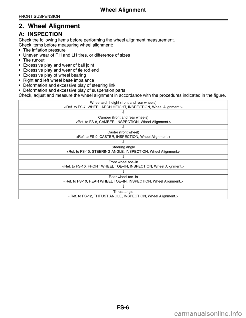
Check, adjust and measure the wheel alignment in accordance with the procedures indicated in the figure.
Wheel arch height (front and rear wheels)
↓
Camber (front and rear wheels)
↓
Caster (front wheel)
↓
Steering angle
↓
Fr o nt wh ee l to e –i n
↓
Rear wheel toe–in
↓
Thrust angle
Page 855 of 2453
FS-7
Wheel Alignment
FRONT SUSPENSION
1. WHEEL ARCH HEIGHT
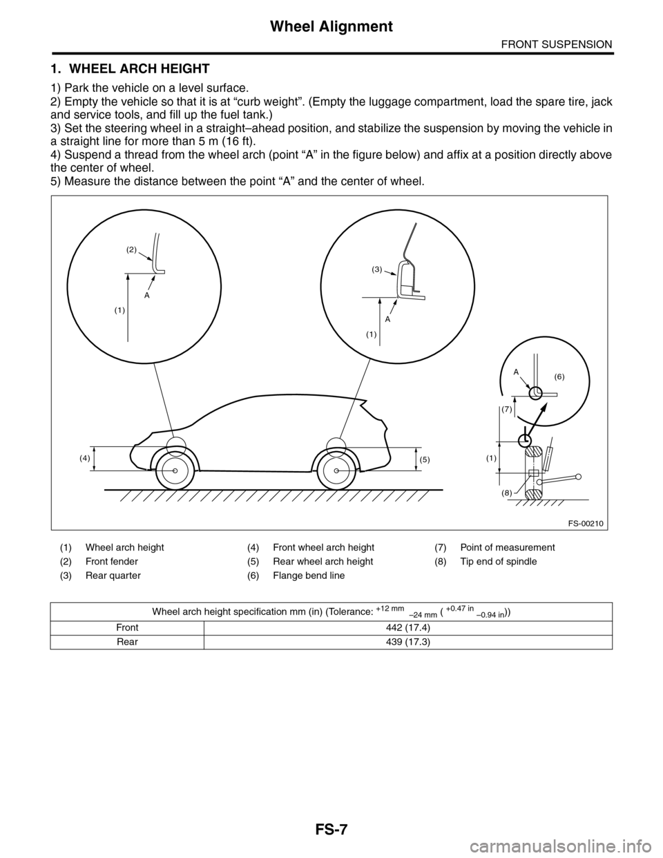
1) Park the vehicle on a level surface.
2) Empty the vehicle so that it is at “curb weight”. (Empty the luggage compartment, load the spare tire, jack
and service tools, and fill up the fuel tank.)
3) Set the steering wheel in a straight–ahead position, and stabilize the suspension by moving the vehicle in
a straight line for more than 5 m (16 ft).
4) Suspend a thread from the wheel arch (point “A” in the figure below) and affix at a position directly above
the center of wheel.
5) Measure the distance between the point “A” and the center of wheel.
(1) Wheel arch height (4) Front wheel arch height (7) Point of measurement
(2) Front fender (5) Rear wheel arch height (8) Tip end of spindle
(3) Rear quarter (6) Flange bend line
Wheel arch height specification mm (in) (Tolerance: +12 mm –24 mm ( +0.47 in –0.94 in))
Front 442 (17.4)
Rear 439 (17.3)
A
A
A
(4)
(1)
(2)
(3)
(1)
(5)(1)
(7)
(6)
(8)
FS-00210
Page 858 of 2453
FS-10
Wheel Alignment
FRONT SUSPENSION
4. STEERING ANGLE
•INSPECTION
•ADJUSTMENT
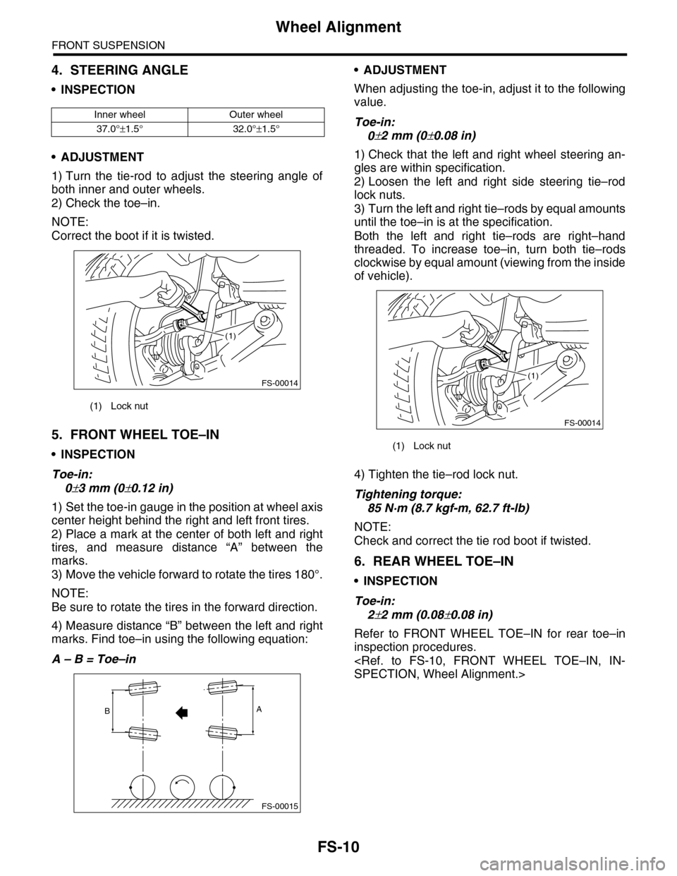
1) Turn the tie-rod to adjust the steering angle of
both inner and outer wheels.
2) Check the toe–in.
NOTE:
Correct the boot if it is twisted.
5. FRONT WHEEL TOE–IN
•INSPECTION
Toe-in:
0±3 mm (0±0.12 in)
1) Set the toe-in gauge in the position at wheel axis
center height behind the right and left front tires.
2) Place a mark at the center of both left and right
tires, and measure distance “A” between the
marks.
3) Move the vehicle forward to rotate the tires 180°.
NOTE:
Be sure to rotate the tires in the forward direction.
4) Measure distance “B” between the left and right
marks. Find toe–in using the following equation:
A – B = Toe–in
•ADJUSTMENT
When adjusting the toe-in, adjust it to the following
value.
Toe-in:
0±2 mm (0±0.08 in)
1) Check that the left and right wheel steering an-
gles are within specification.
2) Loosen the left and right side steering tie–rod
lock nuts.
3) Turn the left and right tie–rods by equal amounts
until the toe–in is at the specification.
Both the left and right tie–rods are right–hand
threaded. To increase toe–in, turn both tie–rods
clockwise by equal amount (viewing from the inside
of vehicle).
4) Tighten the tie–rod lock nut.
Tightening torque:
85 N·m (8.7 kgf-m, 62.7 ft-lb)
NOTE:
Check and correct the tie rod boot if twisted.
6. REAR WHEEL TOE–IN
•INSPECTION
Toe-in:
2±2 mm (0.08±0.08 in)
Refer to FRONT WHEEL TOE–IN for rear toe–in
inspection procedures.
Inner wheel Outer wheel
37.0°±1.5° 32.0°±1.5°
(1) Lock nut
FS-00014
(1)
FS-00015
AB
(1) Lock nut
FS-00014
(1)
Page 871 of 2453
FS-23
Front Crossmember
FRONT SUSPENSION
8. Front Crossmember
A: REMOVAL
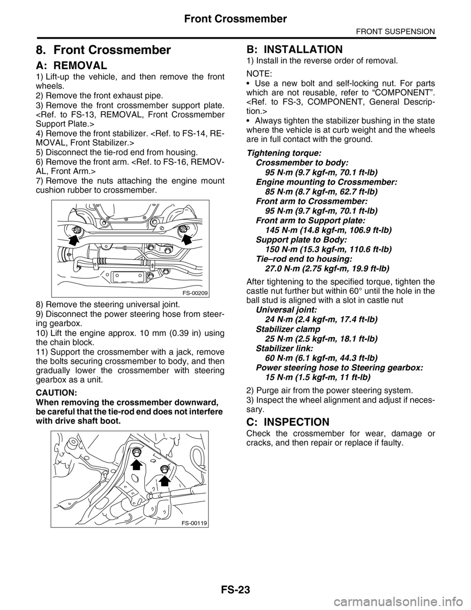
1) Lift-up the vehicle, and then remove the front
wheels.
2) Remove the front exhaust pipe.
3) Remove the front crossmember support plate.
4) Remove the front stabilizer.
5) Disconnect the tie-rod end from housing.
6) Remove the front arm.
7) Remove the nuts attaching the engine mount
cushion rubber to crossmember.
8) Remove the steering universal joint.
9) Disconnect the power steering hose from steer-
ing gearbox.
10) Lift the engine approx. 10 mm (0.39 in) using
the chain block.
11) Support the crossmember with a jack, remove
the bolts securing crossmember to body, and then
gradually lower the crossmember with steering
gearbox as a unit.
CAUTION:
When removing the crossmember downward,
be careful that the tie-rod end does not interfere
with drive shaft boot.
B: INSTALLATION
1) Install in the reverse order of removal.
NOTE:
•Use a new bolt and self-locking nut. For parts
which are not reusable, refer to “COMPONENT”.
•Always tighten the stabilizer bushing in the state
where the vehicle is at curb weight and the wheels
are in full contact with the ground.
Tightening torque:
Crossmember to body:
95 N·m (9.7 kgf-m, 70.1 ft-lb)
Engine mounting to Crossmember:
85 N·m (8.7 kgf-m, 62.7 ft-lb)
Front arm to Crossmember:
95 N·m (9.7 kgf-m, 70.1 ft-lb)
Front arm to Support plate:
145 N·m (14.8 kgf-m, 106.9 ft-lb)
Support plate to Body:
150 N·m (15.3 kgf-m, 110.6 ft-lb)
Tie–rod end to housing:
27.0 N·m (2.75 kgf-m, 19.9 ft-lb)
After tightening to the specified torque, tighten the
castle nut further but within 60° until the hole in the
ball stud is aligned with a slot in castle nut
Universal joint:
24 N·m (2.4 kgf-m, 17.4 ft-lb)
Stabilizer clamp
25 N·m (2.5 kgf-m, 18.1 ft-lb)
Stabilizer link:
60 N·m (6.1 kgf-m, 44.3 ft-lb)
Power steering hose to Steering gearbox:
15 N·m (1.5 kgf-m, 11 ft-lb)
2) Purge air from the power steering system.
3) Inspect the wheel alignment and adjust if neces-
sary.
C: INSPECTION
Check the crossmember for wear, damage or
cracks, and then repair or replace if faulty.
FS-00209
FS-00119
Page 882 of 2453
PS-2
General Description
POWER ASSISTED SYSTEM (POWER STEERING)
1. General Description
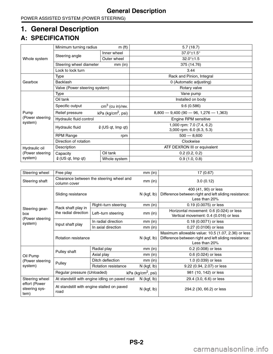
A: SPECIFICATION
Whole system
Minimum turning radius m (ft) 5.7 (18.7)
Steering angleInner wheel 37.0°±1.5°
Outer wheel 32.0°±1.5
Steering wheel diameter mm (in) 375 (14.76)
Lock to lock turn 3.44
Gearbox
Ty p e R a c k a n d P i n i o n , I n t e g r a l
Backlash 0 (Automatic adjusting)
Va l ve ( Po w e r s t e e r i n g s y s t e m ) R o t a r y va l ve
Pump
(Power steering
system)
Ty p e Va n e p u m p
Oil tank Installed on body
Specific outputcm3 (cu in)/rev.9.6 (0.586)
Relief pressurekPa (kg/cm2, psi)8,800 — 9,400 (90 — 96, 1,276 — 1,363)
Hydraulic fluid control Engine RPM sensitive
Hydraulic fluid2(US qt, Imp qt)1,000 rpm: 7.0 (7.4, 6.2)
3,000 rpm: 6.0 (6.3, 5.3)
RPM Range rpm 500 — 8,600
Direction of rotation Clockwise
Hydraulic oil
(Power steering
system)
Description ATF DEXRON III or equivalent
Capacity
2(US qt, Imp qt)
Oil tank 0.2 (0.2, 0.2)
Whole system 0.9 (1.0, 0.8)
Steering wheel Free play mm (in) 17 (0.67)
Steering shaftClearance between the steering wheel and
column covermm (in) 3.0 (0.12)
Steering gear-
box
(Power steering
system)
Sliding resistance N (kgf, lb)
400 (41, 90) or less
Difference between right and left sliding resistance:
Less than 20%
Rack shaft play in
the radial direction
Right–turn steering mm (in) 0.19 (0.0075) or less
Left–turn steering mm (in)Horizontal movement: 0.6 (0.024) or less
Ve r t i c a l m o v e m e n t : 0 . 4 ( 0 . 0 1 6 ) o r l e s s
Input shaft playIn radial direction mm (in) 0.18 (0.0071) or less
In axial direction mm (in) 0.27 (0.0106) or less
Rotation resistance N (kgf, lb)
Maximum allowable value: 10.5 (1.07, 2.36) or less
Difference between right and left sliding resistance:
Less than 20%
Oil Pump
(Power steering
system)
Pulley shaftRadial play mm (in) 0.2 (0.008) or less
Axial play mm (in) 0.6 (0.024) or less
PulleyDitch deflection mm (in) 1.0 (0.039) or less
Rotation resistance N (kgf, lb) 9.22 (0.94, 2.07) or less
Regular pressure (Unloaded)kPa (kg/cm2, psi)981 (10, 142) or less
Steering wheel
effort (Power
steering sys-
tem)
At standstill with engine idling on paved road N (kgf, lb) 29.4 (3.0, 6.6) or less
At standstill with engine stalled on paved
roadN (kgf, lb) 294.2 (30, 66.2) or less
Page 883 of 2453
PS-3
General Description
POWER ASSISTED SYSTEM (POWER STEERING)
B: COMPONENT
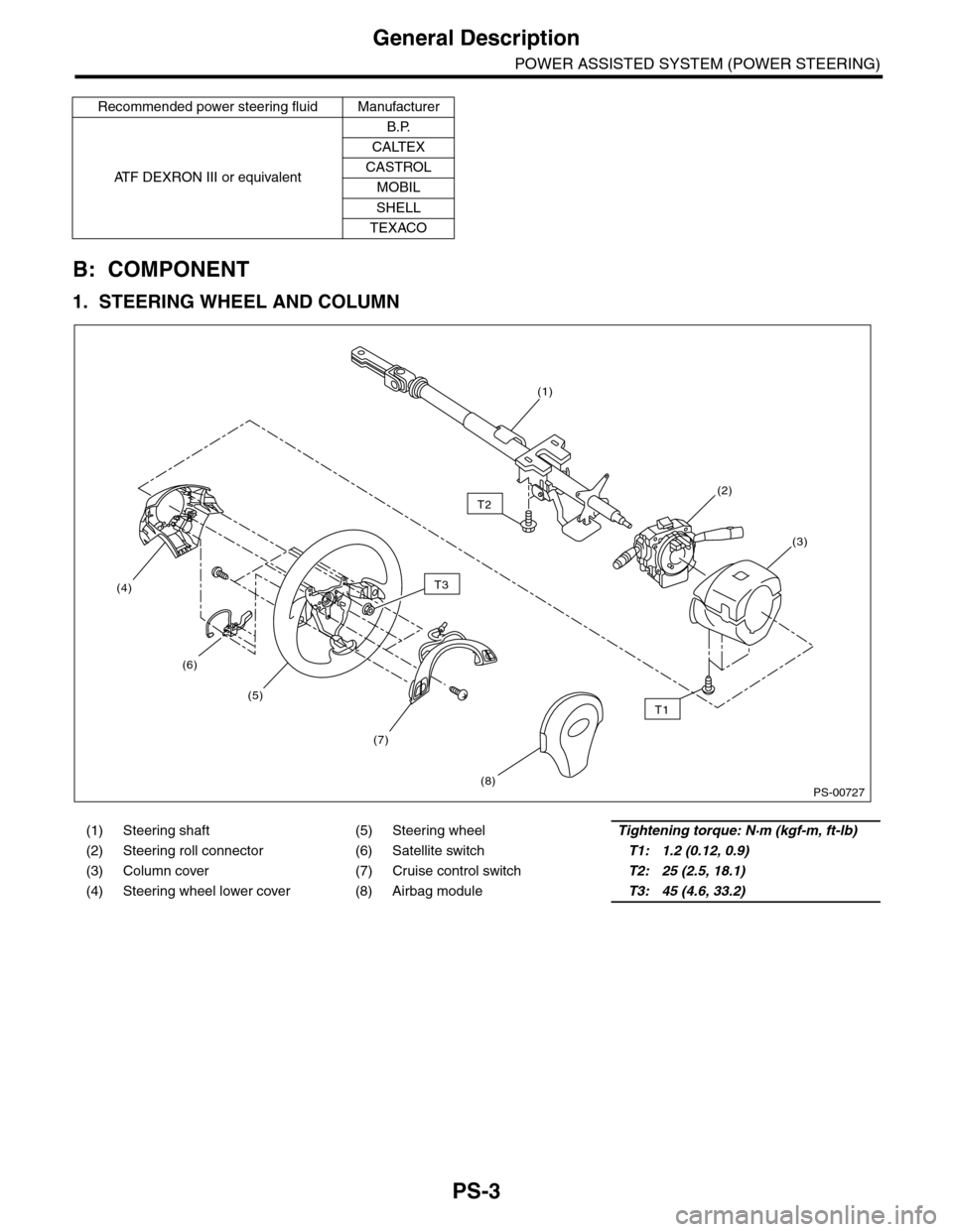
1. STEERING WHEEL AND COLUMN
Recommended power steering fluid Manufacturer
AT F D E X R O N I I I o r e q u i v a l e n t
B.P.
CALTEX
CASTROL
MOBIL
SHELL
TEXACO
(1) Steering shaft (5) Steering wheelTightening torque: N·m (kgf-m, ft-lb)
(2) Steering roll connector (6) Satellite switchT1: 1.2 (0.12, 0.9)
(3) Column cover (7) Cruise control switchT2: 25 (2.5, 18.1)
(4) Steering wheel lower cover (8) Airbag moduleT3: 45 (4.6, 33.2)
PS-00727
T2
T1
T3
(5)
(1)
(2)
(3)
(4)
(8)
(6)
(7)
Page 892 of 2453
PS-12
Steering Wheel
POWER ASSISTED SYSTEM (POWER STEERING)
2. Steering Wheel
A: REMOVAL
1) Disconnect the ground cable from the battery.
2) Set the tire to the straight–ahead position.
3) Remove the airbag module.
WARNING:
Always refer to “Air Bag System” before per-
forming service on the air bag modules.
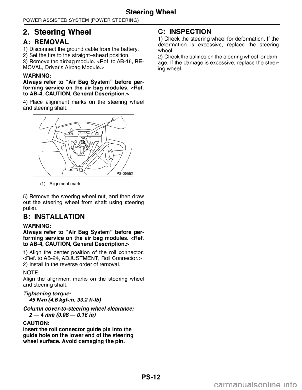
4) Place alignment marks on the steering wheel
and steering shaft.
5) Remove the steering wheel nut, and then draw
out the steering wheel from shaft using steering
puller.
B: INSTALLATION
WARNING:
Always refer to “Air Bag System” before per-
forming service on the air bag modules.
1) Align the center position of the roll connector.
2) Install in the reverse order of removal.
NOTE:
Align the alignment marks on the steering wheel
and steering shaft.
Tightening torque:
45 N·m (4.6 kgf-m, 33.2 ft-lb)
Column cover-to-steering wheel clearance:
2 — 4 mm (0.08 — 0.16 in)
CAUTION:
Insert the roll connector guide pin into the
guide hole on the lower end of the steering
wheel surface. Avoid damaging the pin.
C: INSPECTION
1) Check the steering wheel for deformation. If the
deformation is excessive, replace the steering
wheel.
2) Check the splines on the steering wheel for dam-
age. If the damage is excessive, replace the steer-
ing wheel.
(1) Alignment mark
(1)
PS-00552
Page 893 of 2453
PS-13
Universal Joint
POWER ASSISTED SYSTEM (POWER STEERING)
3. Universal Joint
A: REMOVAL
1) Remove the steering wheel.
2) Place alignment marks on universal joint.
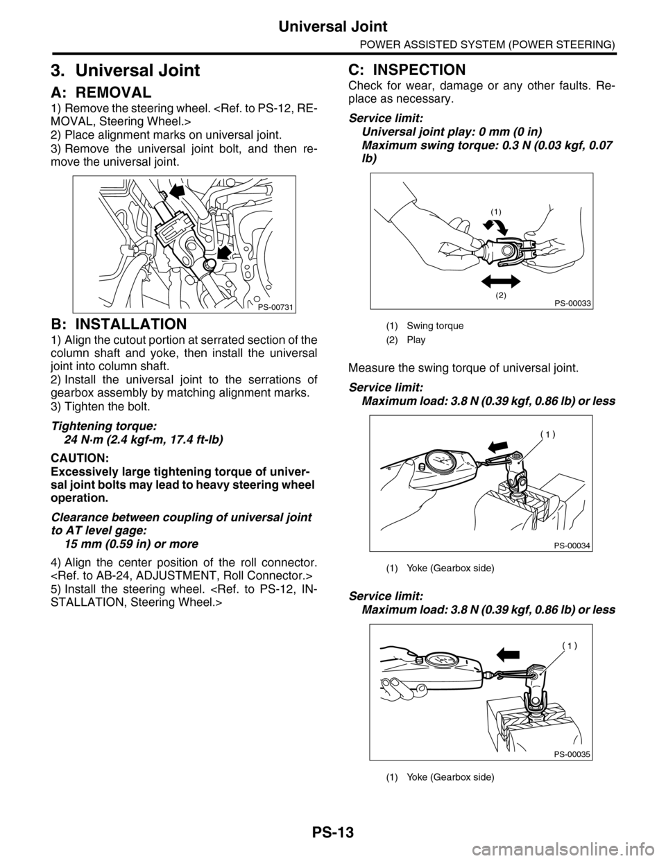
3) Remove the universal joint bolt, and then re-
move the universal joint.
B: INSTALLATION
1) Align the cutout portion at serrated section of the
column shaft and yoke, then install the universal
joint into column shaft.
2) Install the universal joint to the serrations of
gearbox assembly by matching alignment marks.
3) Tighten the bolt.
Tightening torque:
24 N·m (2.4 kgf-m, 17.4 ft-lb)
CAUTION:
Excessively large tightening torque of univer-
sal joint bolts may lead to heavy steering wheel
operation.
Clearance between coupling of universal joint
to AT level gage:
15 mm (0.59 in) or more
4) Align the center position of the roll connector.
5) Install the steering wheel.
C: INSPECTION
Check for wear, damage or any other faults. Re-
place as necessary.
Service limit:
Universal joint play: 0 mm (0 in)
Maximum swing torque: 0.3 N (0.03 kgf, 0.07
lb)
Measure the swing torque of universal joint.
Service limit:
Maximum load: 3.8 N (0.39 kgf, 0.86 lb) or less
Service limit:
Maximum load: 3.8 N (0.39 kgf, 0.86 lb) or less
PS-00731
(1) Swing torque
(2) Play
(1) Yoke (Gearbox side)
(1) Yoke (Gearbox side)
PS-00033
(1)
(2)
PS-00034
PS-00035