Gnd SUBARU TRIBECA 2009 1.G Service Workshop Manual
[x] Cancel search | Manufacturer: SUBARU, Model Year: 2009, Model line: TRIBECA, Model: SUBARU TRIBECA 2009 1.GPages: 2453, PDF Size: 46.32 MB
Page 53 of 2453
AB(diag)-29
Airbag Control Module I/O Signal
AIRBAG SYSTEM (DIAGNOSTICS)
6. Airbag Control Module I/O Signal
A: ELECTRICAL SPECIFICATION
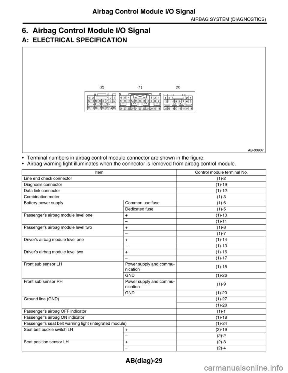
•Terminal numbers in airbag control module connector are shown in the figure.
•Airbag warning light illuminates when the connector is removed from airbag control module.
Item Control module terminal No.
Line end check connector(1)-2
Diagnosis connector(1)-19
Data link connector(1)-12
Combination meter(1)-3
Battery power supply Common use fuse (1)-6
Dedicated fuse (1)-5
Passenger’s airbag module level one + (1)-10
–(1)-11
Passenger’s airbag module level two + (1)-8
–(1)-7
Driver’s airbag module level one + (1)-14
–(1)-13
Driver’s airbag module level two + (1)-16
–(1)-17
Fr o nt su b se ns or L H Powe r su p pl y a n d co mmu-
nication(1)-15
GND (1)-26
Fr o nt su b se ns or RH Powe r su p pl y a n d co mmu-
nication(1)-9
GND (1)-20
Ground line (GND)(1)-27
(1)-28
Passenger’s airbag OFF indicator (1)-1
Passenger’s airbag ON indicator (1)-18
Passenger’s seat belt war ning light (integrated module) (1)-24
Seat belt buckle switch LH + (2)-19
–(2)-2
Seat position sensor LH + (2)-3
–(2)-4
AB-00937
123456789101112
1314151617181920
123456789101112
1314151617181920
1234567891011121314151617
1819202122232425262728
(1)(2) (3)
Page 54 of 2453
AB(diag)-30
Airbag Control Module I/O Signal
AIRBAG SYSTEM (DIAGNOSTICS)
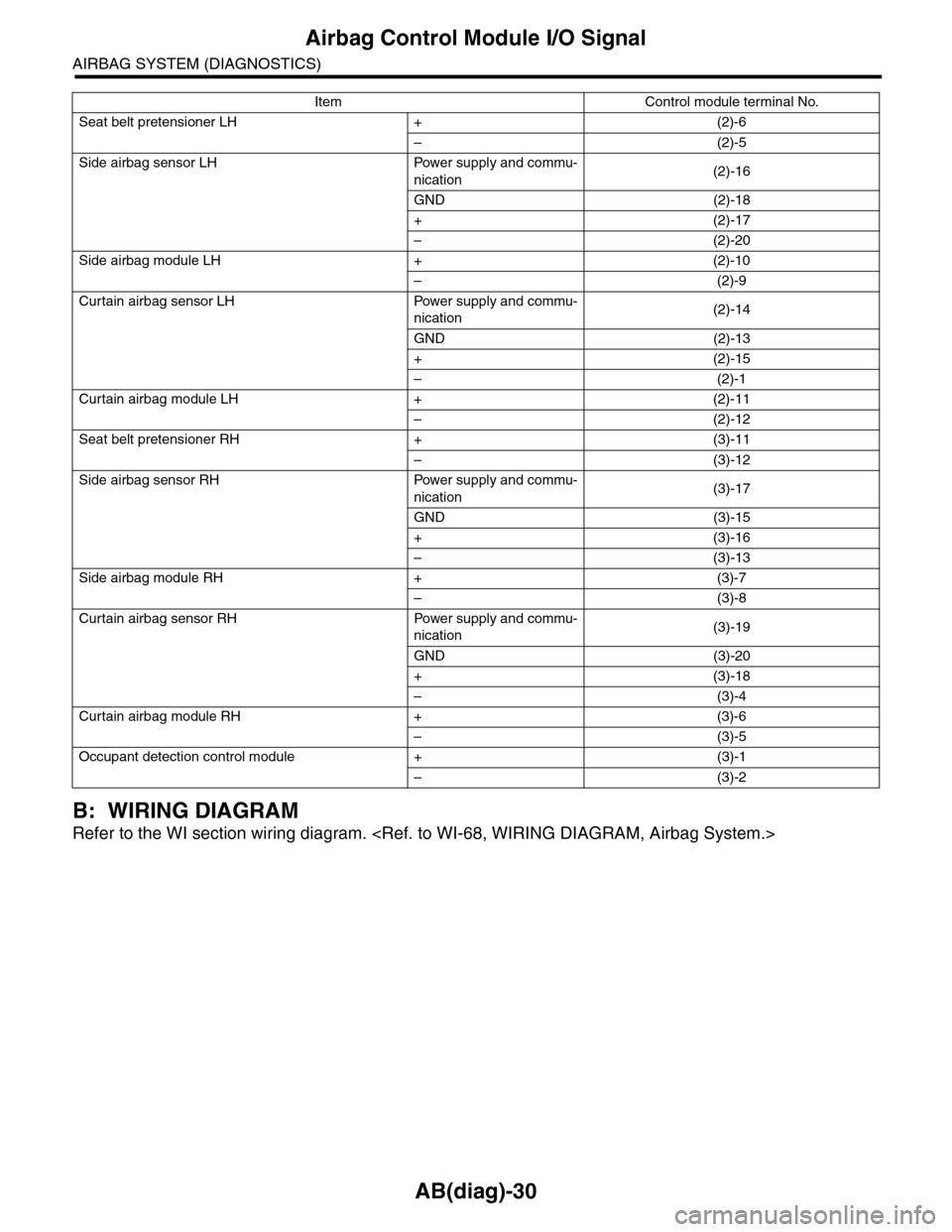
B: WIRING DIAGRAM
Refer to the WI section wiring diagram.
Seat belt pretensioner LH + (2)-6
–(2)-5
Side airbag sensor LH Power supply and commu-
nication(2)-16
GND (2)-18
+(2)-17
–(2)-20
Side airbag module LH + (2)-10
–(2)-9
Curtain airbag sensor LH Power supply and commu-
nication(2)-14
GND (2)-13
+(2)-15
–(2)-1
Curtain airbag module LH + (2)-11
–(2)-12
Seat belt pretensioner RH + (3)-11
–(3)-12
Side airbag sensor RH Power supply and commu-
nication(3)-17
GND (3)-15
+(3)-16
–(3)-13
Side airbag module RH + (3)-7
–(3)-8
Curtain airbag sensor RH Power supply and commu-
nication(3)-19
GND (3)-20
+(3)-18
–(3)-4
Curtain airbag module RH + (3)-6
–(3)-5
Occupant detection control module + (3)-1
–(3)-2
Item Control module terminal No.
Page 173 of 2453
CC(ETC)(diag)-6
Engine Control Module (ECM) I/O Signal
CRUISE CONTROL SYSTEM (DIAGNOSTICS)
4. Engine Control Module (ECM) I/O Signal
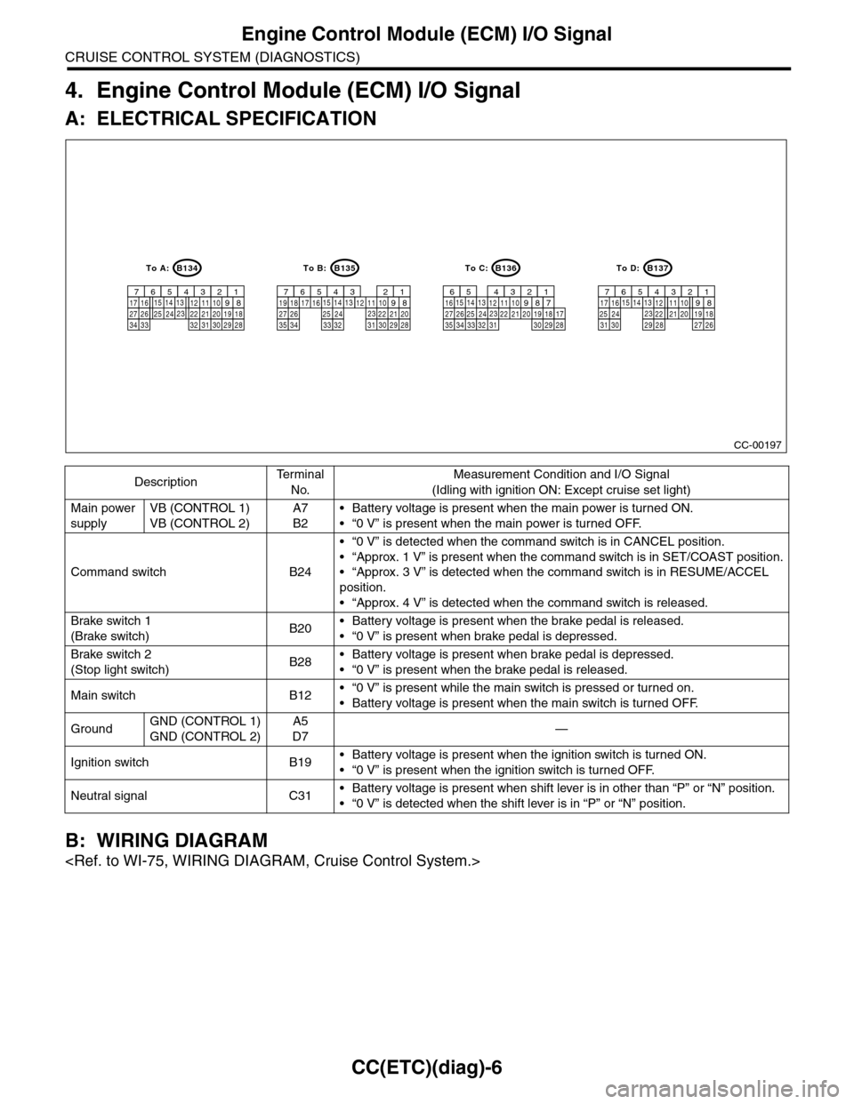
A: ELECTRICAL SPECIFICATION
B: WIRING DIAGRAM
DescriptionTe r m i n a l
No.
Measurement Condition and I/O Signal
(Idling with ignition ON: Except cruise set light)
Main power
supply
VB (CONTROL 1)
VB (CONTROL 2)
A7
B2
•Battery voltage is present when the main power is turned ON.
•“0 V” is present when the main power is turned OFF.
Command switch B24
•“0 V” is detected when the command switch is in CANCEL position.
•“Approx. 1 V” is present when the command switch is in SET/COAST position.
•“Approx. 3 V” is detected when the command switch is in RESUME/ACCEL
position.
•“Approx. 4 V” is detected when the command switch is released.
Brake switch 1
(Brake switch)B20•Battery voltage is present when the brake pedal is released.
•“0 V” is present when brake pedal is depressed.
Brake switch 2
(Stop light switch)B28•Battery voltage is present when brake pedal is depressed.
•“0 V” is present when the brake pedal is released.
Main switch B12•“0 V” is present while the main switch is pressed or turned on.
•Battery voltage is present when the main switch is turned OFF.
GroundGND (CONTROL 1)
GND (CONTROL 2)
A5
D7—
Ignition switch B19•Battery voltage is present when the ignition switch is turned ON.
•“0 V” is present when the ignition switch is turned OFF.
Neutral signal C31•Battery voltage is present when shift lever is in other than “P” or “N” position.
•“0 V” is detected when the shift lever is in “P” or “N” position.
CC-00197
B134
9
30 29 2832 3120 19 1822 211012 11142434 3327 2617 161234567132315258
B135
9
30 29 2832312022 211012 111424353327 2617 161234567132315258
B136
9
30 29 2832 3120 19 1822 211012 11142434 3327 2616123456132315258
B137
9
29 2820 19 182221101211142417 1612345671323152581819
34
71735303127 26
To D:To C:To B:To A:
Page 466 of 2453
LAN(diag)-10
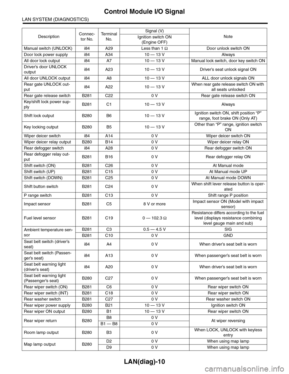
Control Module I/O Signal
LAN SYSTEM (DIAGNOSTICS)
Manual switch (UNLOCK) i84 A29 Less than 1 ΩDoor unlock switch ON
Door lock power supply i84 A34 10 — 13 V Always
All door lock output i84 A7 10 — 13 V Manual lock switch, door key switch ON
Driver’s door UNLOCK
outputi84 A23 10 — 13 V Driver’s seat unlock signal ON
All door UNLOCK output i84 A8 10 — 13 V ALL door unlock signals ON
Rear gate UNLOCK out-
puti84 A22 10 — 13 VWhen rear gate release switch ON with
all seats unlocked
Rear gate release switch B281 C22 0 V Rear gate release switch ON
Key/shift lock power sup-
plyB281 C1 10 — 13 V Always
Shift lock output B280 B6 10 — 13 VIgnition switch ON, shift position “P”
range, foot brake ON (Only AT)
Key locking output B280 B5 10 — 13 VOther than “P” range, ignition switch
ON
Wiper deicer switch i84 A14 0 V Wiper deicer switch ON
Wiper deicer relay output B280 B14 0 V Wiper deicer relay ON
Rear defogger switch i84 A28 0 V Rear defogger switch ON
Rear defogger relay out-
putB281 B16 0 V Rear defogger relay ON
Shift switch (ON) B281 C26 0 V At Manual mode
Shift switch (UP) B281 C15 0 V At Manual mode UP
Shift switch (DOWN) B281 C25 0 V At Manual mode DOWN
Shift button switch B281 C24 0 VWhen shift lever release button is oper-
ated
P range switch B281 C13 0 V Shift range P position
Impact sensor B281 C5 8 V or moreImpact sensor ON (Model with impact
sensor)
Fuel level sensor B281 C19 0 — 102.3 Ω
Resistance differs according to the fuel
level (displays resistance combining
level gauge main and sub)
Ambient temperature sen-
sor
B281 C3 0.5 — 4.5 V SIG
B281 C10 0 V GND
Seat belt switch (driver’s
seat)i84 A4 0 V When driver’s seat belt is worn
Seat belt switch (Passen-
ger’s seat)i84 A13 0 V When passenger’s seat belt is worn
Seat belt warning light
(driver’s seat)i84 A20 0 V When driver’s seat belt is worn
Seat belt warning light
(Passenger’s seat)B280 C27 0 V When passenger’s seat belt is worn
Rear wiper switch (ON) B281 C6 0 V Rear wiper switch ON
Rear wiper switch (INT) B281 C18 0 V Rear wiper switch ON
Rear washer switch B281 C27 0 V Rear washer switch ON
Rear wiper power supply B280 B21 10 — 13 V Ignition switch ON
Rear wiper ON output B280 B1 10 — 13 V Rear wiper switch ON
Rear wiper return B280B8 0 VAt wiper reversingB1 — B8 0 V
Room lamp output B280 B3 0 VWhen LOCK, UNLOCK with keyless
entry
Map lamp output B280D2 0 V When using map lamp
D9 0 V When using map lamp
DescriptionConnec-
tor No.
Te r m i n a l
No.
Signal (V)
NoteIgnition switch ON
(Engine OFF)
Page 584 of 2453
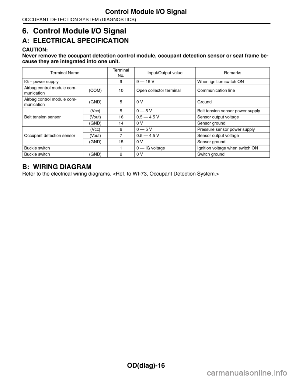
OD(diag)-16
Control Module I/O Signal
OCCUPANT DETECTION SYSTEM (DIAGNOSTICS)
6. Control Module I/O Signal
A: ELECTRICAL SPECIFICATION
CAUTION:
Never remove the occupant detection control module, occupant detection sensor or seat frame be-
cause they are integrated into one unit.
B: WIRING DIAGRAM
Refer to the electrical wiring diagrams.
Te r m i n a l N a m eTe r m i n a l
No.Input/Output value Remarks
IG – power supply 9 9 — 16 V When ignition switch ON
Airbag control module com-
munication(COM) 10 Open collector terminal Communication line
Airbag control module com-
munication(GND) 5 0 V Ground
Belt tension sensor
(Vcc) 5 0 — 5 V Belt tension sensor power supply
(Vout) 16 0.5 — 4.5 V Sensor output voltage
(GND) 14 0 V Sensor ground
Occupant detection sensor
(Vcc) 6 0 — 5 V Pressure sensor power supply
(Vout) 7 0.5 — 4.5 V Sensor output voltage
(GND) 15 0 V Sensor ground
Buckle switch 1 0 — IG voltage Ignition voltage when switch ON
Buckle switch (GND) 2 0 V Switch ground
Page 956 of 2453
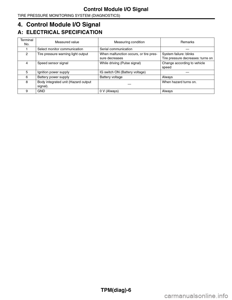
TPM(diag)-6
Control Module I/O Signal
TIRE PRESSURE MONITORING SYSTEM (DIAGNOSTICS)
4. Control Module I/O Signal
A: ELECTRICAL SPECIFICATION
Te r m i n a l
No.Measured value Measuring condition Remarks
1Select monitor communication Serial communication —
2Tire pressure warning light output When malfunction occurs, or tire pres-
sure decreases
System failure: blinks
Tire pressure decreases: turns on
4Speed sensor signal While driving (Pulse signal) Change according to vehicle
speed
5Ignition power supply IG switch ON (Battery voltage) —
6Battery power supply Battery voltage Always
8Body integrated unit (Hazard output
signal).—When hazard turns on.
9GND 0 V (Always) Always
Page 2129 of 2453
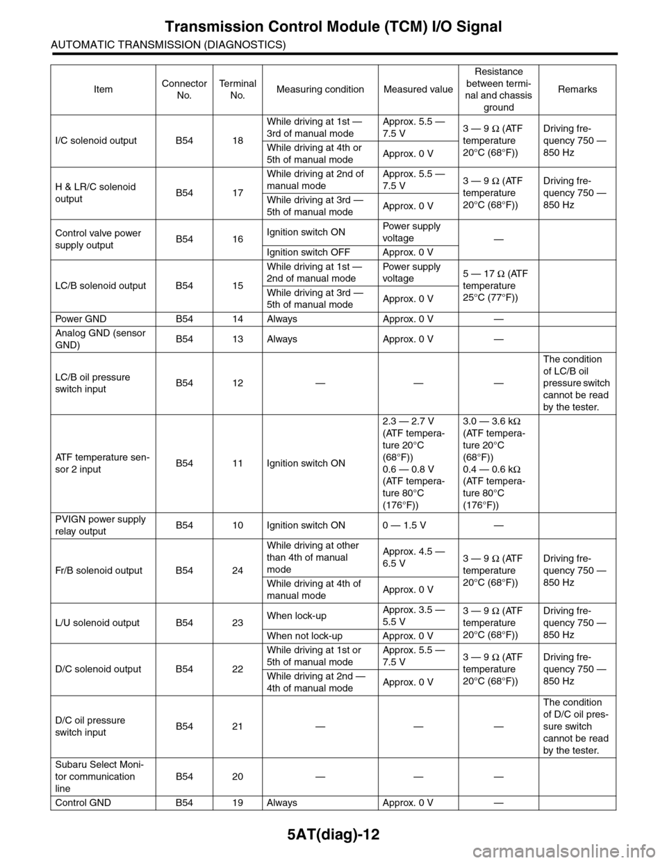
5AT(diag)-12
Transmission Control Module (TCM) I/O Signal
AUTOMATIC TRANSMISSION (DIAGNOSTICS)
I/C solenoid output B54 18
While driving at 1st —
3rd of manual mode
Approx. 5.5 —
7.5 V3 — 9 Ω (ATF
temperature
20°C (68°F))
Driving fre-
quency 750 —
850 HzWhile driving at 4th or
5th of manual modeApprox. 0 V
H & LR/C solenoid
outputB54 17
While driving at 2nd of
manual mode
Approx. 5.5 —
7.5 V3 — 9 Ω (ATF
temperature
20°C (68°F))
Driving fre-
quency 750 —
850 HzWhile driving at 3rd —
5th of manual modeApprox. 0 V
Control valve power
supply outputB54 16Ignition switch ONPow er s up p ly
voltage—
Ignition switch OFF Approx. 0 V
LC/B solenoid output B54 15
While driving at 1st —
2nd of manual mode
Pow er s up p ly
voltage5 — 17 Ω (ATF
temperature
25°C (77°F))
While driving at 3rd —
5th of manual modeApprox. 0 V
Pow er GN D B 5 4 1 4 A lways A pp r ox . 0 V —
Analog GND (sensor
GND)B54 13 Always Approx. 0 V —
LC/B oil pressure
switch inputB54 12 — — —
The condition
of LC/B oil
pressure switch
cannot be read
by the tester.
AT F t e m p e r a t u r e s e n -
sor 2 inputB54 11 Ignition switch ON
2.3 — 2.7 V
(ATF tempera-
ture 20°C
(68°F))
0.6 — 0.8 V
(ATF tempera-
ture 80°C
(176°F))
3.0 — 3.6 kΩ
(ATF tempera-
ture 20°C
(68°F))
0.4 — 0.6 kΩ
(ATF tempera-
ture 80°C
(176°F))
PVIGN power supply
relay outputB54 10 Ignition switch ON 0 — 1.5 V —
Fr / B so le n oi d o u tp u t B 5 4 2 4
While driving at other
than 4th of manual
mode
Approx. 4.5 —
6.5 V3 — 9 Ω (ATF
temperature
20°C (68°F))
Driving fre-
quency 750 —
850 HzWhile driving at 4th of
manual modeApprox. 0 V
L/U solenoid output B54 23When lock-upApprox. 3.5 —
5.5 V3 — 9 Ω (ATF
temperature
20°C (68°F))
Driving fre-
quency 750 —
850 HzWhen not lock-up Approx. 0 V
D/C solenoid output B54 22
While driving at 1st or
5th of manual mode
Approx. 5.5 —
7.5 V3 — 9 Ω (ATF
temperature
20°C (68°F))
Driving fre-
quency 750 —
850 HzWhile driving at 2nd —
4th of manual modeApprox. 0 V
D/C oil pressure
switch inputB54 21 — — —
The condition
of D/C oil pres-
sure switch
cannot be read
by the tester.
Subaru Select Moni-
tor communication
line
B54 20 — — —
Control GND B54 19 Always Approx. 0 V —
ItemConnector
No.
Te r m i n a l
No.Measuring condition Measured value
Resistance
between termi-
nal and chassis
ground
Remarks
Page 2131 of 2453
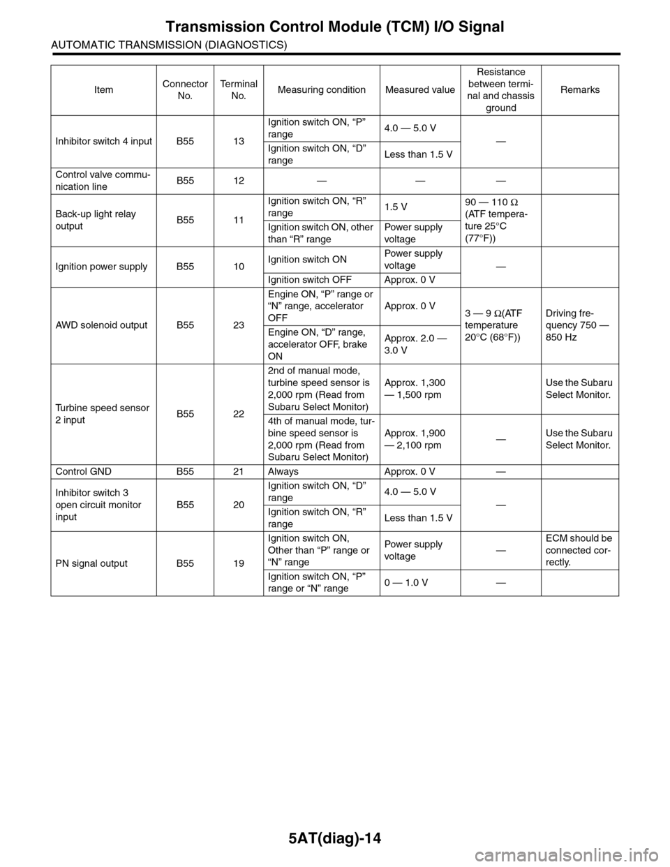
5AT(diag)-14
Transmission Control Module (TCM) I/O Signal
AUTOMATIC TRANSMISSION (DIAGNOSTICS)
Inhibitor switch 4 input B55 13
Ignition switch ON, “P”
range4.0 — 5.0 V
—
Ignition switch ON, “D”
rangeLess than 1.5 V
Control valve commu-
nication lineB55 12 — — —
Back-up light relay
outputB55 11
Ignition switch ON, “R”
range1.5 V90 — 110 Ω
(ATF tempera-
ture 25°C
(77°F))
Ignition switch ON, other
than “R” range
Pow er s up p ly
voltage
Ignition power supply B55 10Ignition switch ONPow er s up p ly
voltage—
Ignition switch OFF Approx. 0 V
AW D s o le n oi d o u tp u t B 5 5 2 3
Engine ON, “P” range or
“N” range, accelerator
OFF
Approx. 0 V3 — 9 Ω(ATF
temperature
20°C (68°F))
Driving fre-
quency 750 —
850 HzEngine ON, “D” range,
accelerator OFF, brake
ON
Approx. 2.0 —
3.0 V
Tu r b i n e s p e e d s e n s o r
2 inputB55 22
2nd of manual mode,
turbine speed sensor is
2,000 rpm (Read from
Subaru Select Monitor)
Approx. 1,300
— 1,500 rpm
Use the Subaru
Select Monitor.
4th of manual mode, tur-
bine speed sensor is
2,000 rpm (Read from
Subaru Select Monitor)
Approx. 1,900
— 2,100 rpm—Use the Subaru
Select Monitor.
Control GND B55 21 Always Approx. 0 V —
Inhibitor switch 3
open circuit monitor
input
B55 20
Ignition switch ON, “D”
range4.0 — 5.0 V
—
Ignition switch ON, “R”
rangeLess than 1.5 V
PN signal output B55 19
Ignition switch ON,
Other than “P” range or
“N” range
Pow er s up p ly
voltage—
ECM should be
connected cor-
rectly.
Ignition switch ON, “P”
range or “N” range0 — 1.0 V —
ItemConnector
No.
Te r m i n a l
No.Measuring condition Measured value
Resistance
between termi-
nal and chassis
ground
Remarks
Page 2294 of 2453
WI-10
Basic Diagnostic Procedure
WIRING SYSTEM
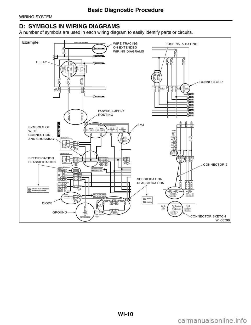
D: SYMBOLS IN WIRING DIAGRAMS
A number of symbols are used in each wiring diagram to easily identify parts or circuits.
WI-03798
LRLWRL3725
MAIN FUSE BOX (M/B)
MB-11MB-10
F39
P-SUP-02B
P-SUP-02A
P-SUP-02C
No.3 10ANo.9 15ANo.8 15A
SBF-1 100A
HEAD-LIGHTRELAYRH
HEAD-LIGHTRELAYLH
G
P-SUP-04D
H/L(2L)-01RLLWGRLB
TO POWER SUPPLY ROUTINGMB-10M/B FUSE NO. 8MB-11M/B FUSE NO. 9FB-16F/B FUSE NO. 11(IG)MB-5HEADLIGHTRELAY
LW 4R3YLLWRYL2
YB1RY2
LW2R1YL3
P
LW B 1RA1
F44
F45
F23
F7B61
B62
B
RL2R1YL3
B71
B112
LY8RY7YBB1716
3
1716
UPLOWPA S SHFHUHLE
SMJLB H1
B36SMJ
DIODE
: WITHOUT REAR DEFOGGER: WITH REAR DEFOGGER
PA R K I N GBRAKESWITCH
R4
OFFHCTCEL
LOWHIGH
HEADLIGHT RH
HEADLIGHT LH
LIGHTING SWITCH
DIMMER & PASSINGSWITCH
LOWHIGH
B51A:B52C:F41G: (GRAY)
(BLACK)(BLACK)
FB-37
D4D7BGD11
A2WR G4BLG1BR D10
FB-35FB-34
123456712345678
LgBOr
FUSE &RELAYBOX(F/B)
i5B:B51A:
B152D:B52C:
B158E:
F41G:F40F:
FB-36
A3BGG7
No.5 10A
P-SUP-03H
P-SUP-03F
P-SUP-04KP-SUP-04J
No.1 20ANo.2 15A
SBF-6 30A
LR2R3L1R3BW 2W
SBF-2 50ASBF-3 50ASBF-4 50A
F36F38F68
P-SUP-04E
P-SUP-04MP-SUP-04L
P-SUP-03I
P-SUP-04G
12345678
F44B11212F23
123
F7
SPECIFICATIONCLASSIFICATION
SPECIFICATIONCLASSIFICATION
2
LY1313
WROR
ORWRREF. TO FOG (H4)-01
REF. TO ST (MT)-01REF. TO ST (AT)-01
REF. TO FOG (H6)-01
REF. TO GND-02
CONNECTOR-1
FUSE No. & RATING
CONNECTOR-2
CONNECTOR SKETCH
RELAY
WIRE TRACINGON EXTENDEDWIRING DIAGRAMS
Example
DIODE
GROUND
POWER SUPPLYROUTING
SMJSYMBOLS OFWIRECONNECTIONAND CROSSING
PP17R3B99
PP7R1B97
WGWGSDSD: WAGON: SEDANSDWG
Page 2303 of 2453
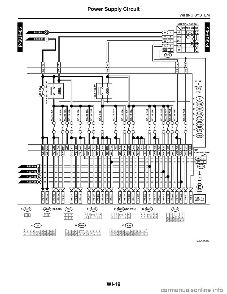
WI-19
Power Supply Circuit
WIRING SYSTEM
WI-08029
P-SUP-05P-SUP-05
WL
B11
NO. 7 15A
2YR3GY
R
G1D4
BrR
GY
E5F7
G
F8F3
NO. 20 10ANO. 23 15ANO. 24 15ANO. 30 30ANO. 31 7.5ANO.4 7.5ANO. 11 7.5ANO. 18 10ANO. 5 7.5ANO. 12 15ANO. 19 7.5ANO. 25 15ANO. 26 7.5ANO. 32 7.5ANO. 33 7.5ANO. 22 15ANO. 21 7.5ANO. 13 20ANO. 6 7.5A
A19
FB-17FB-18FB-19FB-21
A10
WL
C19
P-SUP-02G
P-SUP-02F
P-SUP-03K
P-SUP-02A
P-SUP-03J
P-SUP-02B
FUSE&RELAYBOX(F/B)
i5A:
R168B:
B52C:
B152D:
B158E:
B159F:
B373G:
L
F2
WB
OPCONNECTOR
FB-40FB-39
GB
C11D2
Br
G2
GY
H2
WG
D1
GOrGOr
A3D8
GY
D3C1
FB-41FB-42FB-43FB-44FB-45FB-46ST-1ST-2
B228
B72
IGNITION SWITCH
3+B
4
6
L
WB
1
2
ACC
ACCOFF
IG2
ST
ONST
IG1
W
G
Y
FB-20
D6
ACCESSORY RELAY 1
IG2 RELAY
FB-23FB-24FB-25FB-27FB-28FB-29FB-32FB-34FB-35FB-36FB-37FB-38
YL
B1
YG
C3
YG
A17
YR
C7
YR
F4
YB
A1
YR
D7
YR
A5B18
YW
B14
YLGY
C8A6
GB
D9C16
GLBrW
A20
GR
A8
GR
C24H1
B
B
B373B158E:G:
B52C:
B159F:B152D:B228
A:i5
1234 5678910 11 12 13 14 15 16 17 18 19 20
1576283491234785612345678910131415
123456789101112
3412 8910 1112 13 14 15 16 17 18 19 20 21 22 23 24567
12
B:R168
12345678910 11 12 13 14 15 16 17 18 19 20
B72
134562
REF. TOGND-02
(BROWN)
AB35H:
FB-48FB-49
GYGYGOr
FB-47
12
AB35H:(BLACK)