ad blue SUBARU TRIBECA 2009 1.G Service Workshop Manual
[x] Cancel search | Manufacturer: SUBARU, Model Year: 2009, Model line: TRIBECA, Model: SUBARU TRIBECA 2009 1.GPages: 2453, PDF Size: 46.32 MB
Page 19 of 2453
AB-20
Curtain Airbag Module
AIRBAG SYSTEM
C: INSPECTION
CAUTION:
Refer to “CAUTION” of “General Description”
before handling the airbag module.
Check for the following, and replace the damaged
parts with new parts.
cations After a Collision.>
1) With side collision (when curtain airbag is de-
ployed)
•Curtain airbag module assembly
•Roof Trim
•Front pillar upper trim
•Front piller pad (blue)
•Center pillar upper trim
•Center piller pad (green)
•Rear quarter upper trim
•Rear quarter piller pad (red)
•Airbag guide
2) When damage is found by visual check
•Assist grip
•Assist grip bracket
•Curtain airbag harness and connector on body
side.
3) With side collision (when curtain airbag is not de-
ployed)
Check the roof trim, pillar trim and airbag module
visually, and then replace them with new ones if
damaged or cracked.
Specially inspect the damage of airbag module
body, mounting bracket and harness connector.
4) Without side collision (dirt and damage of cover)
Replace the corresponding part with a new one.
Page 1086 of 2453
VDC-5
General Description
VEHICLE DYNAMICS CONTROL (VDC)
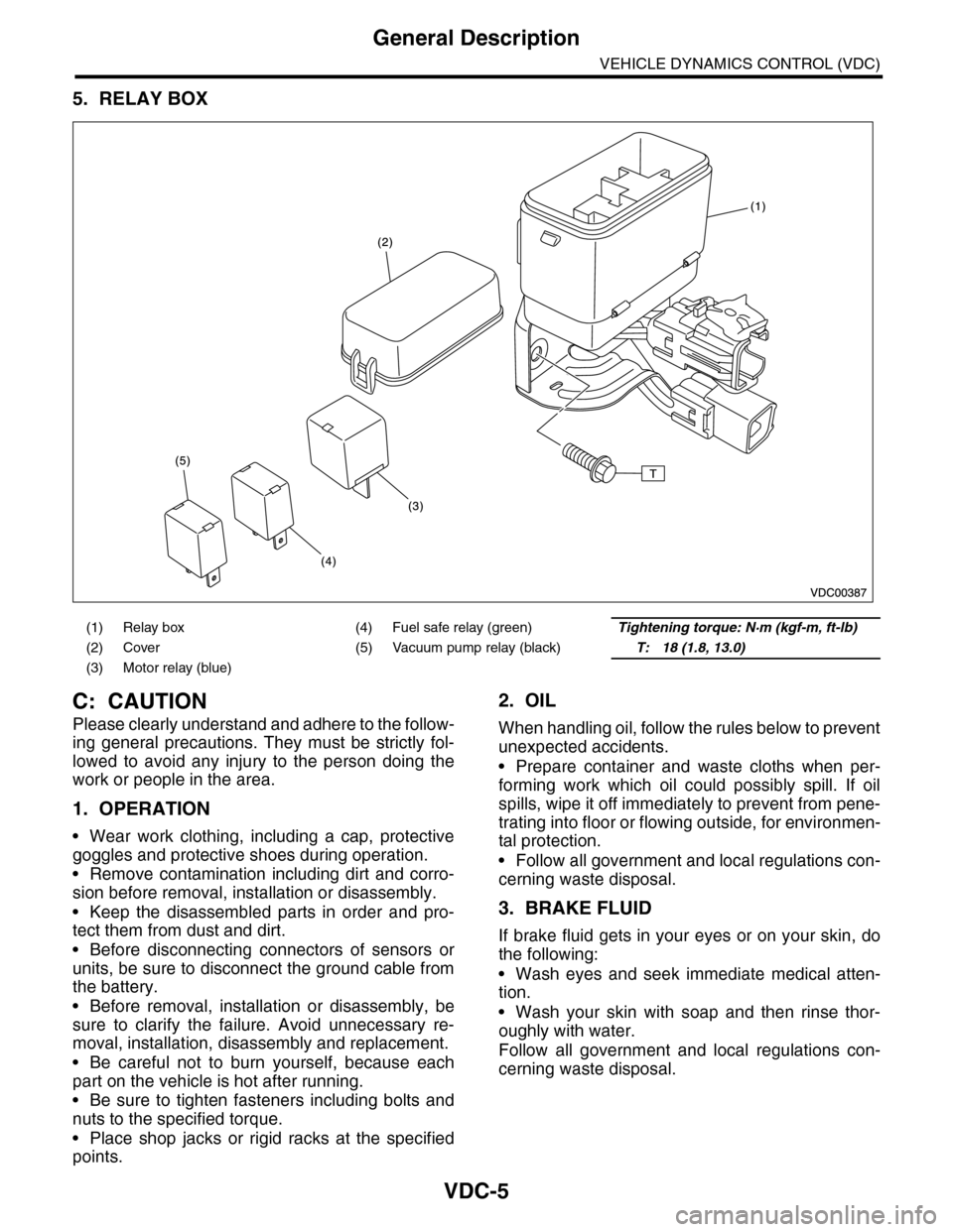
5. RELAY BOX
C: CAUTION
Please clearly understand and adhere to the follow-
ing general precautions. They must be strictly fol-
lowed to avoid any injury to the person doing the
work or people in the area.
1. OPERATION
•Wear work clothing, including a cap, protective
goggles and protective shoes during operation.
•Remove contamination including dirt and corro-
sion before removal, installation or disassembly.
•Keep the disassembled parts in order and pro-
tect them from dust and dirt.
•Before disconnecting connectors of sensors or
units, be sure to disconnect the ground cable from
the battery.
•Before removal, installation or disassembly, be
sure to clarify the failure. Avoid unnecessary re-
moval, installation, disassembly and replacement.
•Be careful not to burn yourself, because each
part on the vehicle is hot after running.
•Be sure to tighten fasteners including bolts and
nuts to the specified torque.
•Place shop jacks or rigid racks at the specified
points.
2. OIL
When handling oil, follow the rules below to prevent
unexpected accidents.
•Prepare container and waste cloths when per-
forming work which oil could possibly spill. If oil
spills, wipe it off immediately to prevent from pene-
trating into floor or flowing outside, for environmen-
tal protection.
•Follow all government and local regulations con-
cerning waste disposal.
3. BRAKE FLUID
If brake fluid gets in your eyes or on your skin, do
the following:
•Wash eyes and seek immediate medical atten-
tion.
•Wash your skin with soap and then rinse thor-
oughly with water.
Follow all government and local regulations con-
cerning waste disposal.
(1) Relay box (4) Fuel safe relay (green)Tightening torque: N·m (kgf-m, ft-lb)
(2) Cover (5) Vacuum pump relay (black)T: 18 (1.8, 13.0)
(3) Motor relay (blue)
Page 1912 of 2453
ME(H6DO)-46
Timing Chain Assembly
MECHANICAL
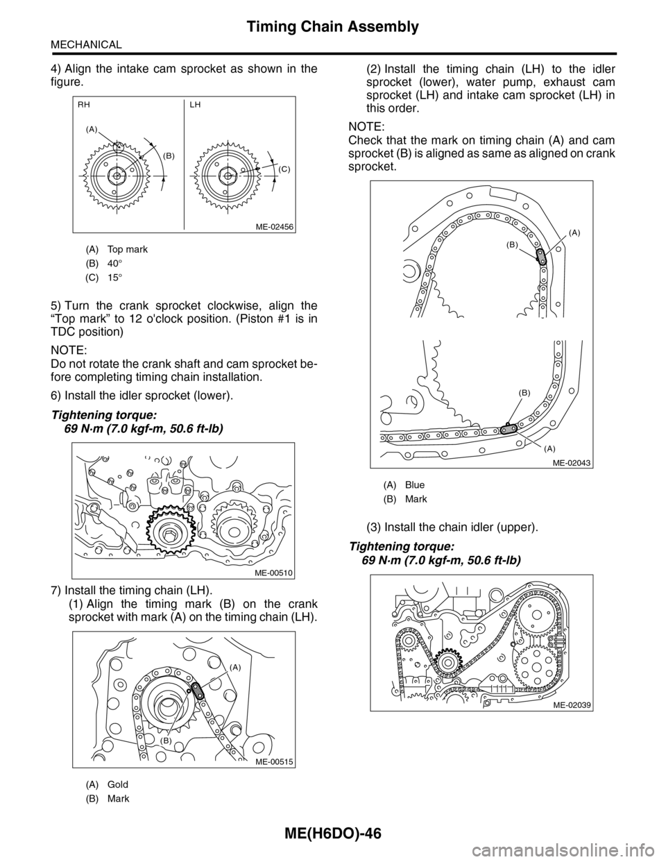
4) Align the intake cam sprocket as shown in the
figure.
5) Turn the crank sprocket clockwise, align the
“Top mark” to 12 o'clock position. (Piston #1 is in
TDC position)
NOTE:
Do not rotate the crank shaft and cam sprocket be-
fore completing timing chain installation.
6) Install the idler sprocket (lower).
Tightening torque:
69 N·m (7.0 kgf-m, 50.6 ft-lb)
7) Install the timing chain (LH).
(1) Align the timing mark (B) on the crank
sprocket with mark (A) on the timing chain (LH).
(2) Install the timing chain (LH) to the idler
sprocket (lower), water pump, exhaust cam
sprocket (LH) and intake cam sprocket (LH) in
this order.
NOTE:
Check that the mark on timing chain (A) and cam
sprocket (B) is aligned as same as aligned on crank
sprocket.
(3) Install the chain idler (upper).
Tightening torque:
69 N·m (7.0 kgf-m, 50.6 ft-lb)
(A) Top mark
(B) 40°
(C) 15°
(A) Gold
(B) Mark
(B)
(A)
LHRH
(C)
ME-02456
ME-00510
(A)
(B)
ME-00515
(A) Blue
(B) Mark
(A)
(B)
(A)
(B)
ME-02043
ME-02039
Page 1913 of 2453
ME(H6DO)-47
Timing Chain Assembly
MECHANICAL
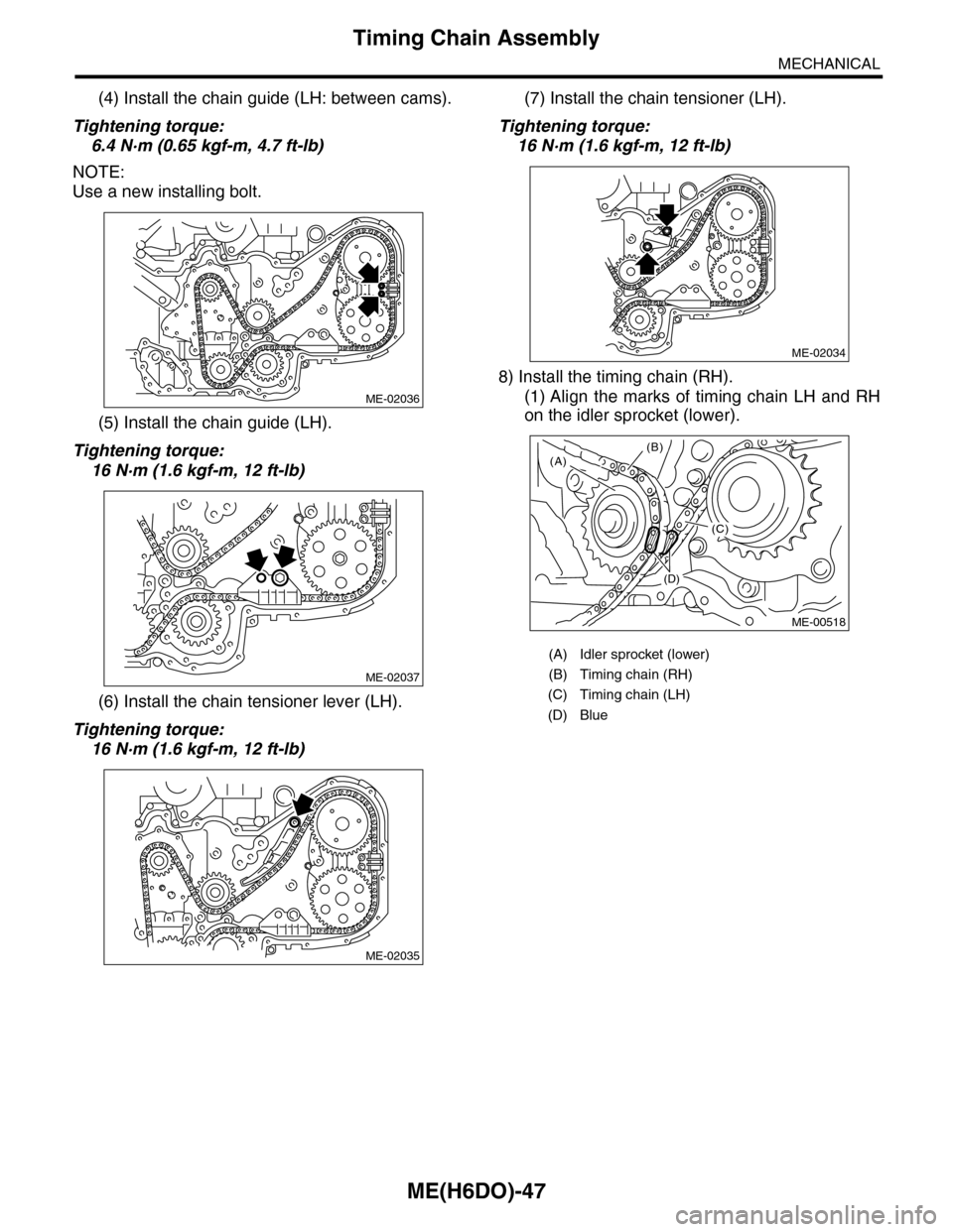
(4) Install the chain guide (LH: between cams).
Tightening torque:
6.4 N·m (0.65 kgf-m, 4.7 ft-lb)
NOTE:
Use a new installing bolt.
(5) Install the chain guide (LH).
Tightening torque:
16 N·m (1.6 kgf-m, 12 ft-lb)
(6) Install the chain tensioner lever (LH).
Tightening torque:
16 N·m (1.6 kgf-m, 12 ft-lb)
(7) Install the chain tensioner (LH).
Tightening torque:
16 N·m (1.6 kgf-m, 12 ft-lb)
8) Install the timing chain (RH).
(1) Align the marks of timing chain LH and RH
on the idler sprocket (lower).
ME-02036
ME-02037
ME-02035
(A) Idler sprocket (lower)
(B) Timing chain (RH)
(C) Timing chain (LH)
(D) Blue
ME-02034
(A)(B)
(C)
(D)
ME-00518
Page 2277 of 2453
![SUBARU TRIBECA 2009 1.G Service Workshop Manual CS-25
Select Lever
CONTROL SYSTEMS
D: ASSEMBLY
1) Clean all the parts before assembly.
2) Apply grease [Multemp AC-D, and SH-W or
equivalent] to each part. <Ref. to CS-2, AT SE-
LECT LE SUBARU TRIBECA 2009 1.G Service Workshop Manual CS-25
Select Lever
CONTROL SYSTEMS
D: ASSEMBLY
1) Clean all the parts before assembly.
2) Apply grease [Multemp AC-D, and SH-W or
equivalent] to each part. <Ref. to CS-2, AT SE-
LECT LE](/img/17/7322/w960_7322-2276.png)
CS-25
Select Lever
CONTROL SYSTEMS
D: ASSEMBLY
1) Clean all the parts before assembly.
2) Apply grease [Multemp AC-D, and SH-W or
equivalent] to each part.
tion.>
3) Assemble in the reverse order of disassembly.
NOTE:
•Refer to “COMPONENT” for each tightening
torque.
•When pressing in the shift position pin, insert
from the left side of the vehicle.
•Affix the harness of the shift button switch and
the mode change switch at the marked positions.
•Connect the terminals of all switches to the re-
spective connectors.
4) After completing installation, shift the select le-
ver from the “P” range to the “D” range, then check
whether or not the selection indicator in the combi-
nation meter and the select lever position matches.
Also check whether the pointer and position mark
matches, and what the operating force is.
E: INSPECTION
1) Inspect the removed parts by comparing with
new ones for deformation, damage and wear. Re-
pair or replace if defective.
2) Confirm the select lever operating condition be-
fore assembly. Normal if it operates smoothly. CS-00641
(A) Mode change switch (color code: Yellow)
(B) Shift button switch (color code: Brown)
(C) Mode change switch and shift button switch
ground (color code: White)
(D) Shift up switch (color code: Green)
(E) Shift up switch (color code: Gray)
(F) Shift up/down switch ground (color code: Blue)
(G) “P” range switch (wire color: Red)
(H) Shift lock solenoid (color code: Blue)
(I) Shift lock solenoid (color code: Black)
(J) Indicator lamp (color code: Blue)
CS-00642
5432112 11 10 9876
(J)
(J)(F)(E)(D)(A)(B)(C)
(H) (G)(I)
Page 2282 of 2453
CS-30
AT Shift Lock Solenoid and “P” Range Switch
CONTROL SYSTEMS
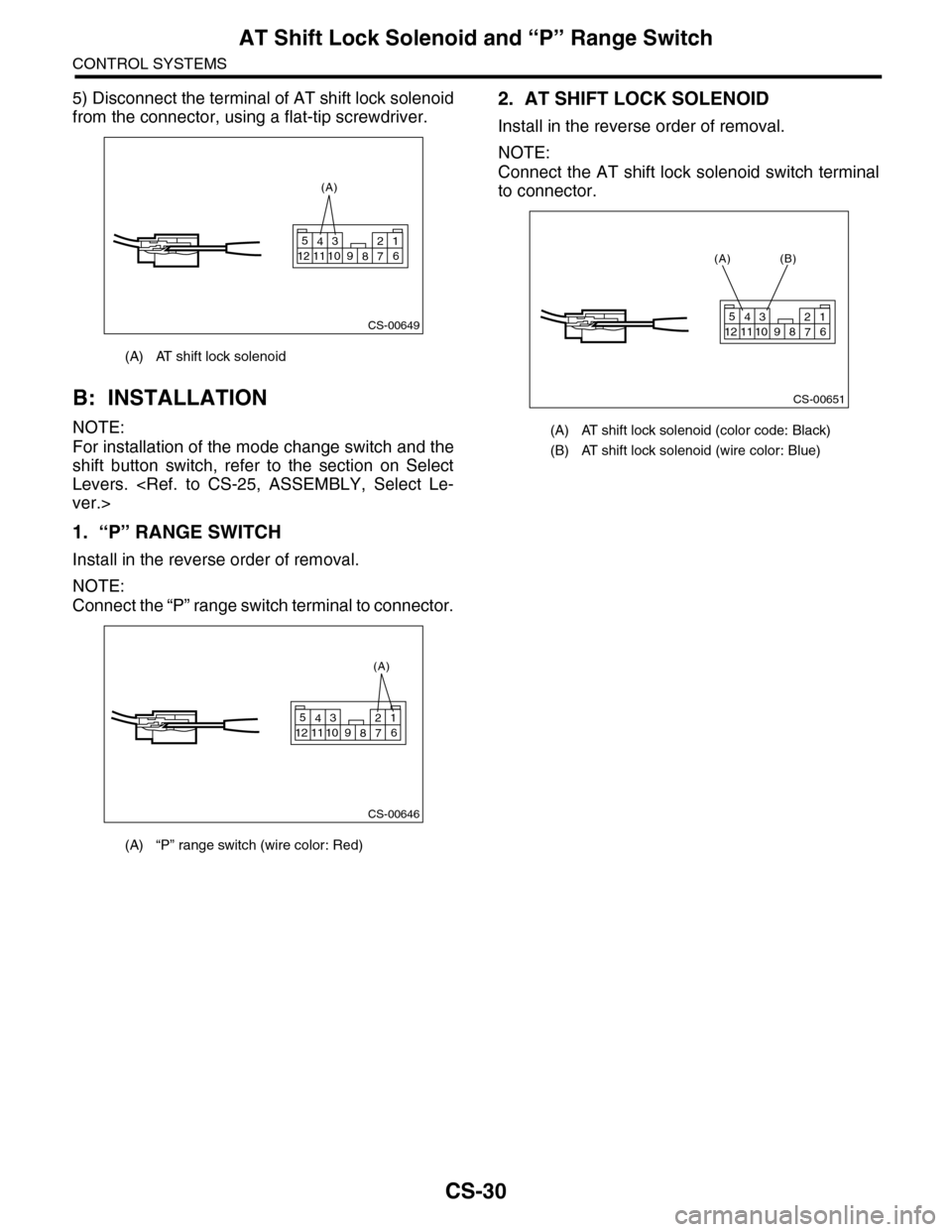
5) Disconnect the terminal of AT shift lock solenoid
from the connector, using a flat-tip screwdriver.
B: INSTALLATION
NOTE:
For installation of the mode change switch and the
shift button switch, refer to the section on Select
Levers.
1. “P” RANGE SWITCH
Install in the reverse order of removal.
NOTE:
Connect the “P” range switch terminal to connector.
2. AT SHIFT LOCK SOLENOID
Install in the reverse order of removal.
NOTE:
Connect the AT shift lock solenoid switch terminal
to connector.
(A) AT shift lock solenoid
(A) “P” range switch (wire color: Red)
CS-00649
5432112 11 10 9876
(A)
CS-00646
5432112 11 10 9876
(A)
(A) AT shift lock solenoid (color code: Black)
(B) AT shift lock solenoid (wire color: Blue)
CS-00651
5432112 11 10 9876
(A) (B)
Page 2290 of 2453
WI-6
Basic Diagnostic Procedure
WIRING SYSTEM
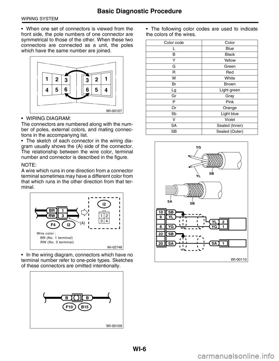
•When one set of connectors is viewed from the
front side, the pole numbers of one connector are
symmetrical to those of the other. When these two
connectors are connected as a unit, the poles
which have the same number are joined.
•WIRING DIAGRAM:
The connectors are numbered along with the num-
ber of poles, external colors, and mating connec-
tions in the accompanying list.
•The sketch of each connector in the wiring dia-
gram usually shows the (A) side of the connector.
The relationship between the wire color, terminal
number and connector is described in the figure.
NOTE:
A wire which runs in one direction from a connector
terminal sometimes may have a different color from
that which runs in the other direction from that ter-
minal.
•In the wiring diagram, connectors which have no
terminal number refer to one-pole types. Sketches
of these connectors are omitted intentionally.
•The following color codes are used to indicate
the colors of the wires.
WI-00107
112233
445566
WI-02748
Wire color :BR (No. 1 terminal)RW (No. 3 terminal)
i2
34
12
BR
RW
i2F4
1
3
(A)
WI-00109
BB
B15F10
Color code Color
LBlue
BBlack
YYellow
GGreen
RRed
WWhite
Br Brown
Lg Light green
Gr Gray
PPink
Or Orange
Sb Light blue
VViolet
SA Sealed (Inner)
SB Sealed (Outer)
WI-00110
YL 2
YG 1
SB10
YL9
YG8
SA 1
SB22
SA20
YG
YLSB
SBSA
Page 2300 of 2453
WI-16
Power Supply Circuit
WIRING SYSTEM
WI-08026
P-SUP-02P-SUP-02
WR
BR
WB21BR3
B14B7C10
GENERATOR
MAIN FUSE BOX(M/B)
BATTERY
MB-2
F26
MB-29MB-1MB-9MB-8MB-6
A7A9
A16
P-SUP-05B
P-SUP-05A
P-SUP-03C
NO. 4 25A
MAINSBF 120A
P-SUP-04I
P-SUP-04H
P-SUP-03D
NO. 2 25ANO. 8 20ANO. 3 25ANO. 5 20ANO. 1 30ANO. 16 7.5A
NO. 10 25A
SBF-1 50ASBF-8 50ASBF-6 50ASBF-3 50ASBF-2 50A
E5E6
RL
G7H8
GOrGB
WH4B19
ALT-1
B433B145G:
12
F26
123
B186H:(BROWN)B144D:(BLUE)F35C:
A:
12345678123456789101112
F37
F:
P-SUP-05G
P-SUP-05F
P-SUP-04E
MAIN FANRELAY 1
REAR DEFOGGER
RELAY
WW
F37A:
B143B:
F35C:
B144D:
F36E:
B433F:
B145G:
B186H:
LR
D9
G
D3
W
D2
R
D6E3D1
RY
D5
WR
D7B11
L
D8
MB-5
1234567
157628349
1234 5678910 11 12 13 14 15 16 17 18 19 20
B:B143
1234 5678910 11 12 13 14 15 16 17 18 19 20
CURRENT FROM IGNITIONSWITCH "IG" TERMINAL
OTHER CURRENT
BATTERY CURRENT
CURRENT FROM IGNITIONSWITCH "ACC" TERMINAL
GRLWLg
F36E:
(BROWN)
Page 2301 of 2453
WI-17
Power Supply Circuit
WIRING SYSTEM
WI-08027
P-SUP-03P-SUP-03
WB
H6
W
H5G4
MAIN FUSE BOX
P-SUP-05K
P-SUP-05J
NO. 14 15ANO. 13 7.5ANO. 12 15ANO. 11 15ANO. 15 20A
NO. 6 15A
SBF-4 30ASBF-7 30ASBF-5 30A
BWWG
H3
BR
G6H7
YRWY
G1G5F2F1
WL
BrBrR
B18B16
B145G:B186H:(BROWN)B144D:(BLUE)F35C:
123456781234567891011121234 567891011 12 13 1415 16 17 18 19 20
B:B143
NO. 7 15ANO. 9 15A
TAIL AND ILLUMINATION RELAY
F37A:
B143B:
F35C:
B144D:
F36E:
B433F:
B145G:
B186H:
RW
H1B6
RL
C8
RG
C9B15
RB
E1C1C2
R
G3H2
RB
B8
RG
E4
W
G2C11
1234567
157628349
P-SUP-02C
P-SUP-02D
MB-21MB-22MB-26MB-25MB-24MB-33MB-27MB-32MB-28MB-19MB-14MB-23MB-32
WGRW
MB-31MB-18MB-17MB-16MB-15MB-20MB-30
P-SUP-04N
P-SUP-04M
P-SUP-04L
HEADLIGHT RELAY RHHEADLIGHT RELAY LHHORN RELAY
LYBW
F36E:
A:F37
1234 5678910 11 12 13 14 15 16 17 18 19 20
(BROWN)B433
12
F:
Page 2309 of 2453
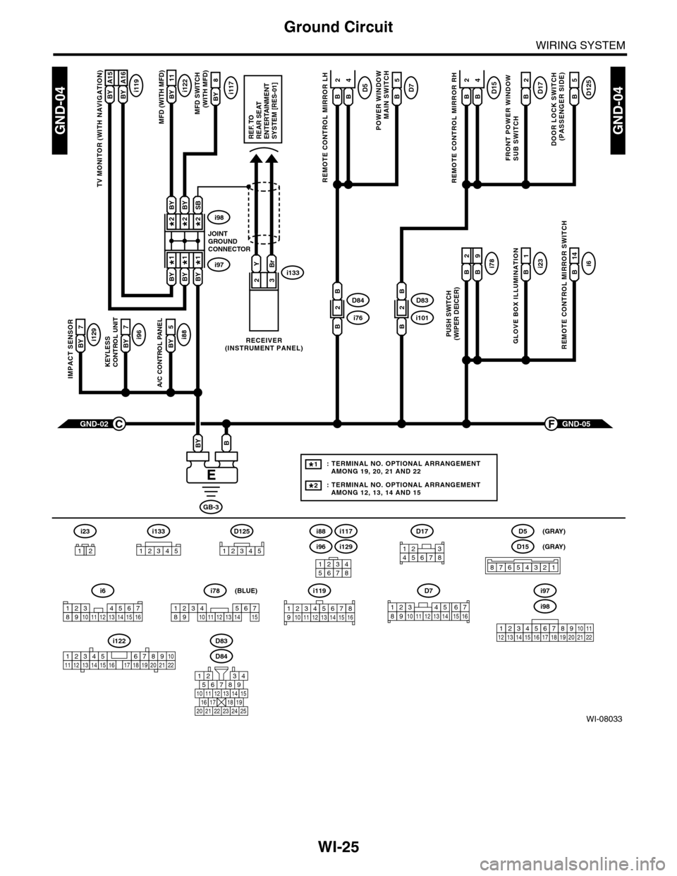
WI-25
Ground Circuit
WIRING SYSTEM
WI-08033
GND-04GND-04
i117BYi122BY 11
8
A/C CONTROL PANEL
i88BY 5
23
GND-05F
KEYLESS CONTROL UNIT
i96BY 7
IMPACT SENSOR
i129BY 7
TV MONITOR (WITH NAVIGATION)
i119BY A15BY A16
GND-02C
GB-3
BBY
D83
MFD (WITH MFD)MFD SWITCH (WITH MFD)
i96
12345678
i6
42
14
REMOTE CONTROL MIRROR SWITCH
i97i133
i98
JOINTGROUNDCONNECTOR
RECEIVER(INSTRUMENT PANEL)
2*2*
1*1*
2*
1*
BYBi231
GLOVE BOX ILLUMINATION
Bi789
PUSH SWITCH(WIPER DEICER)
B
2
BBYBY
SBBYBY
YBr
REF. TOREAR SEATENTERTAINMENT SYSTEM [RES-01]
: TERMINAL NO. OPTIONAL ARRANGEMENT AMONG 19, 20, 21 AND 22
: TERMINAL NO. OPTIONAL ARRANGEMENT AMONG 12, 13, 14 AND 15
1*
2*
D125
5
DOOR LOCK SWITCH(PASSENGER SIDE)
BD17
2
FRONT POWER WINDOW SUB SWITCH
POWER WINDOW
MAIN SWITCH
BD75
BD15
REMOTE CONTROL MIRROR RH
BB
42D5
REMOTE CONTROL MIRROR LH
BB
i1012D83
B
B
i762D84
B
B
D84
i88
i129
i117
567821943
10
2422 23 25
1112131415161718192021
i98
i97
12345678910111213141516171819202122
D7
12345689101112131514716
D17
12345678
D5
D15
87654321
(GRAY)
(GRAY)
i6
12345678910111213141516
i119
123 8910412 13 14 15 1656711
i133
12345
12345678910111213141516171819202122
i122
i78
123456789101112131415
(BLUE)
i23
12
D125
12345