four wheel drive SUBARU TRIBECA 2009 1.G Service Workshop Manual
[x] Cancel search | Manufacturer: SUBARU, Model Year: 2009, Model line: TRIBECA, Model: SUBARU TRIBECA 2009 1.GPages: 2453, PDF Size: 46.32 MB
Page 167 of 2453
CC-5
Cruise Control Command Switch
CRUISE CONTROL SYSTEM
3. Cruise Control Command
Switch
A: REMOVAL
CAUTION:
Before servicing, be sure to read the notes in
the “AB” section for proper handling of the
driver’s airbag module.
1) Set the front wheels in straight ahead position.
2) Turn the ignition switch to OFF.
3) Disconnect the ground cable from battery and
wait for at least 20 seconds before starting work.
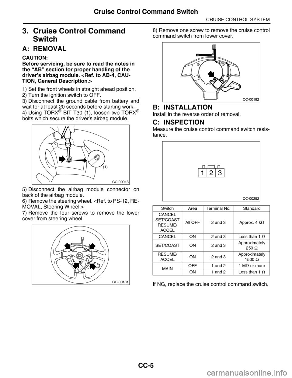
4) Using TORX® BIT T30 (1), loosen two TORX®
bolts which secure the driver’s airbag module.
5) Disconnect the airbag module connector on
back of the airbag module.
6) Remove the steering wheel.
7) Remove the four screws to remove the lower
cover from steering wheel.
8) Remove one screw to remove the cruise control
command switch from lower cover.
B: INSTALLATION
Install in the reverse order of removal.
C: INSPECTION
Measure the cruise control command switch resis-
tance.
If NG, replace the cruise control command switch.
CC-00018
(1)
CC-00181
Switch Area Terminal No. Standard
CANCEL
SET/COAST
RESUME/
ACCEL
All OFF 2 and 3 Approx. 4 kΩ
CANCEL ON 2 and 3 Less than 1 Ω
SET/COAST ON 2 and 3Approximately
250 Ω
RESUME/
ACCELON 2 and 3Approximately
1500 Ω
MAINOFF 1 and 2 1 MΩ or more
ON 1 and 2 Less than 1 Ω
CC-00182
CC-00252
231
Page 543 of 2453
LI-10
Combination Base Switch Assembly
LIGHTING SYSTEM
9. Combination Base Switch
Assembly
A: REMOVAL
1) Remove the driver’s airbag module.
2) Remove the steering wheel.
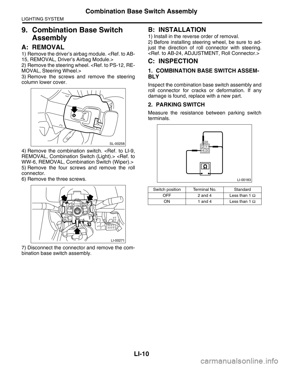
3) Remove the screws and remove the steering
column lower cover.
4) Remove the combination switch.
5) Remove the four screws and remove the roll
connector.
6) Remove the three screws.
7) Disconnect the connector and remove the com-
bination base switch assembly.
B: INSTALLATION
1) Install in the reverse order of removal.
2) Before installing steering wheel, be sure to ad-
just the direction of roll connector with steering.
C: INSPECTION
1. COMBINATION BASE SWITCH ASSEM-
BLY
Inspect the combination base switch assembly and
roll connector for cracks or deformation. If any
damage is found, replace with a new part.
2. PARKING SWITCH
Measure the resistance between parking switch
terminals.
SL-00258
LI-00271
Switch position Terminal No. Standard
OFF 2 and 4 Less than 1 Ω
ON 1 and 4 Less than 1 Ω
LI-00183
1234
Page 818 of 2453
DI-34
General Diagnostic Table
DIFFERENTIALS
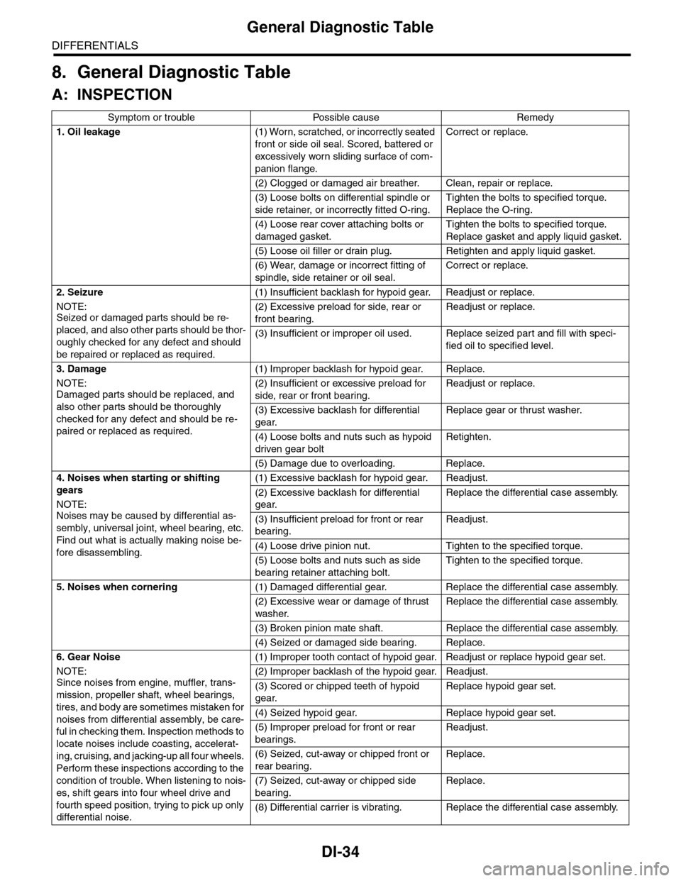
8. General Diagnostic Table
A: INSPECTION
Symptom or trouble Possible cause Remedy
1. Oil leakage(1) Worn, scratched, or incorrectly seated
front or side oil seal. Scored, battered or
excessively wor n sliding surface of com-
panion flange.
Correct or replace.
(2) Clogged or damaged air breather. Clean, repair or replace.
(3) Loose bolts on differential spindle or
side retainer, or incorrectly fitted O-ring.
Tighten the bolts to specified torque.
Replace the O-ring.
(4) Loose rear cover attaching bolts or
damaged gasket.
Tighten the bolts to specified torque.
Replace gasket and apply liquid gasket.
(5) Loose oil filler or drain plug. Retighten and apply liquid gasket.
(6) Wear, damage or incorrect fitting of
spindle, side retainer or oil seal.
Correct or replace.
2. Seizure
NOTE:Seized or damaged parts should be re-
placed, and also other parts should be thor-
oughly checked for any defect and should
be repaired or replaced as required.
(1) Insufficient backlash for hypoid gear. Readjust or replace.
(2) Excessive preload for side, rear or
front bearing.
Readjust or replace.
(3) Insufficient or improper oil used. Replace seized part and fill with speci-
fied oil to specified level.
3. Damage
NOTE:Damaged parts should be replaced, and
also other parts should be thoroughly
checked for any defect and should be re-
paired or replaced as required.
(1) Improper backlash for hypoid gear. Replace.
(2) Insufficient or excessive preload for
side, rear or front bearing.
Readjust or replace.
(3) Excessive backlash for differential
gear.
Replace gear or thrust washer.
(4) Loose bolts and nuts such as hypoid
driven gear bolt
Retighten.
(5) Damage due to overloading. Replace.
4. Noises when starting or shifting
gears
NOTE:
Noises may be caused by differential as-
sembly, universal joint, wheel bearing, etc.
Find out what is actually making noise be-
fore disassembling.
(1) Excessive backlash for hypoid gear. Readjust.
(2) Excessive backlash for differential
gear.
Replace the differential case assembly.
(3) Insufficient preload for front or rear
bearing.
Readjust.
(4) Loose drive pinion nut. Tighten to the specified torque.
(5) Loose bolts and nuts such as side
bearing retainer attaching bolt.
Tighten to the specified torque.
5. Noises when cornering(1) Damaged differential gear. Replace the differential case assembly.
(2) Excessive wear or damage of thrust
washer.
Replace the differential case assembly.
(3) Broken pinion mate shaft. Replace the differential case assembly.
(4) Seized or damaged side bearing. Replace.
6. Gear Noise
NOTE:
Since noises from engine, muffler, trans-
mission, propeller shaft, wheel bearings,
tires, and body are sometimes mistaken for
noises from differential assembly, be care-
ful in checking them. Inspection methods to
locate noises include coasting, accelerat-
ing, cruising, and jacking-up all four wheels.
Perform these inspections according to the
condition of trouble. When listening to nois-
es, shift gears into four wheel drive and
fourth speed position, trying to pick up only
differential noise.
(1) Improper tooth contact of hypoid gear. Readjust or replace hypoid gear set.
(2) Improper backlash of the hypoid gear. Readjust.
(3) Scored or chipped teeth of hypoid
gear.
Replace hypoid gear set.
(4) Seized hypoid gear. Replace hypoid gear set.
(5) Improper preload for front or rear
bearings.
Readjust.
(6) Seized, cut-away or chipped front or
rear bearing.
Replace.
(7) Seized, cut-away or chipped side
bearing.
Replace.
(8) Differential carrier is vibrating. Replace the differential case assembly.
Page 832 of 2453
DS-15
Front Axle
DRIVE SHAFT SYSTEM
10) While depressing the brake pedal, tighten a
new axle nut (olive color) to the specified torque
and lock it securely.
Tightening torque:
240 N·m (24.5 kgf-m, 177 ft-lb)
CAUTION:
•Install the wheel after installation of axle nut.
Failure to follow this rule may damage the
wheel bearing.
•Be sure to tighten the axle nut to specified
torque. Do not overtighten it as this may dam-
age the wheel bearing.
11) After tightening the axle nut, lock it securely.
12) Install the wheel and tighten the wheel nuts to
specified torque.
Tightening torque:
110 N·m (11.2 kgf-m, 81.1 ft-lb)
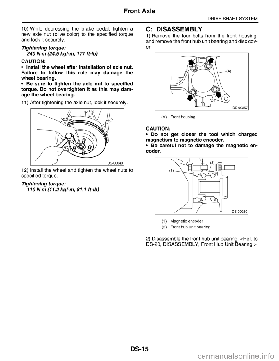
C: DISASSEMBLY
1) Remove the four bolts from the front housing,
and remove the front hub unit bearing and disc cov-
er.
CAUTION:
•Do not get closer the tool which charged
magnetism to magnetic encoder.
•Be careful not to damage the magnetic en-
coder.
2) Disassemble the front hub unit bearing.
DS-00048
(A) Front housing
(1) Magnetic encoder
(2) Front hub unit bearing
(A)
DS-00357
(2)
DS-00250
(1)
Page 833 of 2453
DS-16
Front Axle
DRIVE SHAFT SYSTEM
D: ASSEMBLY
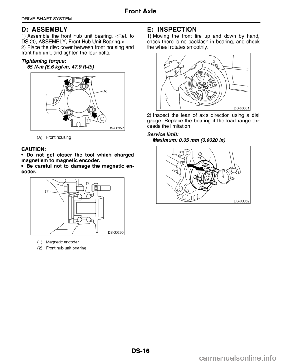
1) Assemble the front hub unit bearing.
2) Place the disc cover between front housing and
front hub unit, and tighten the four bolts.
Tightening torque:
65 N·m (6.6 kgf-m, 47.9 ft-lb)
CAUTION:
•Do not get closer the tool which charged
magnetism to magnetic encoder.
•Be careful not to damage the magnetic en-
coder.
E: INSPECTION
1) Moving the front tire up and down by hand,
check there is no backlash in bearing, and check
the wheel rotates smoothly.
2) Inspect the lean of axis direction using a dial
gauge. Replace the bearing if the load range ex-
ceeds the limitation.
Service limit:
Maximum: 0.05 mm (0.0020 in)(A) Front housing
(1) Magnetic encoder
(2) Front hub unit bearing
(A)
DS-00357
(2)
DS-00250
(1)
DS-00061
DS-00062
Page 835 of 2453
DS-18
Rear Axle
DRIVE SHAFT SYSTEM
B: INSTALLATION
NOTE:
•Be sure to use a new self-locking nut.
•Always tighten the stabilizer bushing in the state
where the vehicle is at curb weight and the wheels
are in full contact with the ground.
Install in the reverse order of removal.
Tightening torque:
Refer to COMPONENT of General Description
for tightening torque.
C: DISASSEMBLY
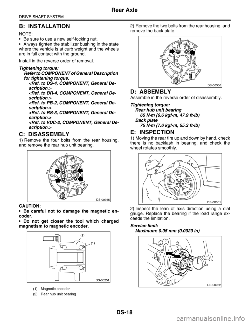
1) Remove the four bolts from the rear housing,
and remove the rear hub unit bearing.
CAUTION:
•Be careful not to damage the magnetic en-
coder.
•Do not get closer the tool which charged
magnetism to magnetic encoder.
2) Remove the two bolts from the rear housing, and
remove the back plate.
D: ASSEMBLY
Assemble in the reverse order of disassembly.
Tightening torque:
Rear hub unit bearing
65 N·m (6.6 kgf-m, 47.9 ft-lb)
Back plate
75 N·m (7.6 kgf-m, 55.3 ft-lb)
E: INSPECTION
1) Moving the rear tire up and down by hand, check
there is no backlash in bearing, and check the
wheel rotates smoothly.
2) Inspect the lean of axis direction using a dial
gauge. Replace the bearing if the load range ex-
ceeds the limitation.
Service limit:
Maximum: 0.05 mm (0.0020 in)
(1) Magnetic encoder
(2) Rear hub unit bearing
DS-00365
DS-00251
(2)
(1)
DS-00366
DS-00061
DS-00062
Page 836 of 2453
DS-19
Front Hub Unit Bearing
DRIVE SHAFT SYSTEM
5. Front Hub Unit Bearing
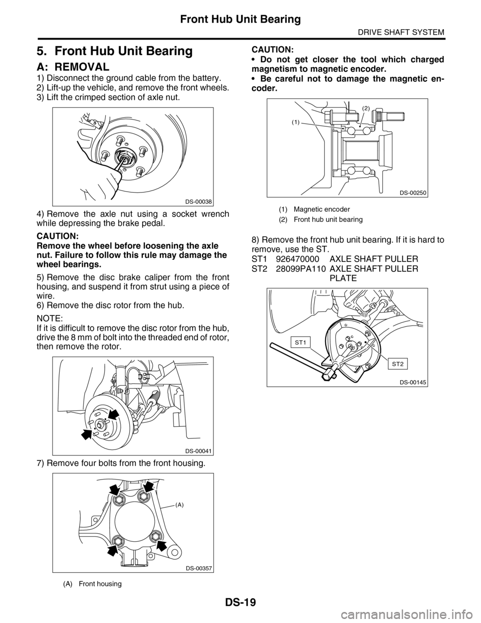
A: REMOVAL
1) Disconnect the ground cable from the battery.
2) Lift-up the vehicle, and remove the front wheels.
3) Lift the crimped section of axle nut.
4) Remove the axle nut using a socket wrench
while depressing the brake pedal.
CAUTION:
Remove the wheel before loosening the axle
nut. Failure to follow this rule may damage the
wheel bearings.
5) Remove the disc brake caliper from the front
housing, and suspend it from strut using a piece of
wire.
6) Remove the disc rotor from the hub.
NOTE:
If it is difficult to remove the disc rotor from the hub,
drive the 8 mm of bolt into the threaded end of rotor,
then remove the rotor.
7) Remove four bolts from the front housing.
CAUTION:
•Do not get closer the tool which charged
magnetism to magnetic encoder.
•Be careful not to damage the magnetic en-
coder.
8) Remove the front hub unit bearing. If it is hard to
remove, use the ST.
ST1 926470000 AXLE SHAFT PULLER
ST2 28099PA110 AXLE SHAFT PULLER
PLATE
(A) Front housing
DS-00038
DS-00041
(A)
DS-00357
(1) Magnetic encoder
(2) Front hub unit bearing
(2)
DS-00250
(1)
DS-00145
ST2
ST1
Page 837 of 2453
DS-20
Front Hub Unit Bearing
DRIVE SHAFT SYSTEM
B: INSTALLATION
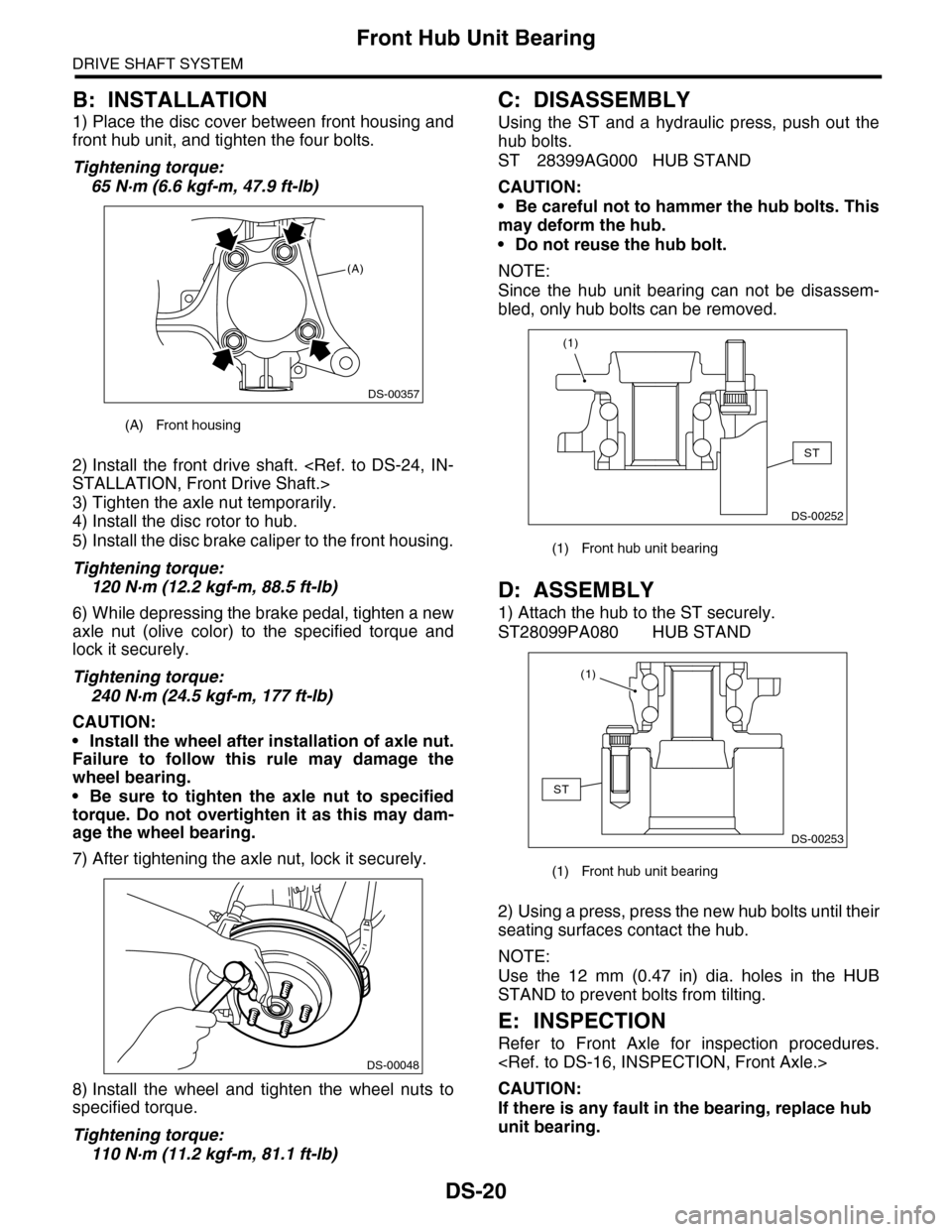
1) Place the disc cover between front housing and
front hub unit, and tighten the four bolts.
Tightening torque:
65 N·m (6.6 kgf-m, 47.9 ft-lb)
2) Install the front drive shaft.
3) Tighten the axle nut temporarily.
4) Install the disc rotor to hub.
5) Install the disc brake caliper to the front housing.
Tightening torque:
120 N·m (12.2 kgf-m, 88.5 ft-lb)
6) While depressing the brake pedal, tighten a new
axle nut (olive color) to the specified torque and
lock it securely.
Tightening torque:
240 N·m (24.5 kgf-m, 177 ft-lb)
CAUTION:
•Install the wheel after installation of axle nut.
Failure to follow this rule may damage the
wheel bearing.
•Be sure to tighten the axle nut to specified
torque. Do not overtighten it as this may dam-
age the wheel bearing.
7) After tightening the axle nut, lock it securely.
8) Install the wheel and tighten the wheel nuts to
specified torque.
Tightening torque:
110 N·m (11.2 kgf-m, 81.1 ft-lb)
C: DISASSEMBLY
Using the ST and a hydraulic press, push out the
hub bolts.
ST 28399AG000 HUB STAND
CAUTION:
•Be careful not to hammer the hub bolts. This
may deform the hub.
•Do not reuse the hub bolt.
NOTE:
Since the hub unit bearing can not be disassem-
bled, only hub bolts can be removed.
D: ASSEMBLY
1) Attach the hub to the ST securely.
ST28099PA080 HUB STAND
2) Using a press, press the new hub bolts until their
seating surfaces contact the hub.
NOTE:
Use the 12 mm (0.47 in) dia. holes in the HUB
STAND to prevent bolts from tilting.
E: INSPECTION
Refer to Front Axle for inspection procedures.
CAUTION:
If there is any fault in the bearing, replace hub
unit bearing.
(A) Front housing
(A)
DS-00357
DS-00048
(1) Front hub unit bearing
(1) Front hub unit bearing
ST
DS-00252
(1)
DS-00253
ST
(1)
Page 838 of 2453
DS-21
Rear Hub Unit Bearing
DRIVE SHAFT SYSTEM
6. Rear Hub Unit Bearing
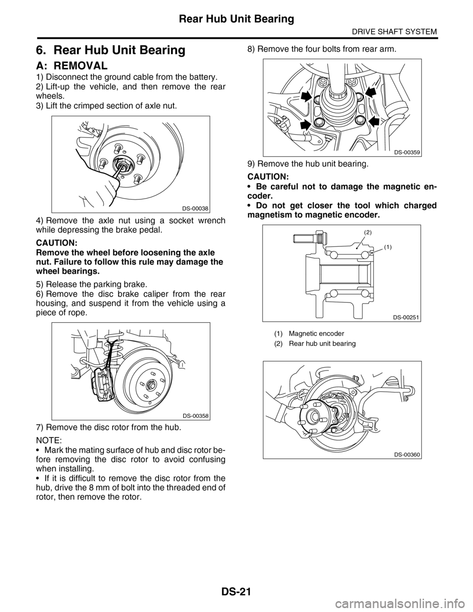
A: REMOVAL
1) Disconnect the ground cable from the battery.
2) Lift-up the vehicle, and then remove the rear
wheels.
3) Lift the crimped section of axle nut.
4) Remove the axle nut using a socket wrench
while depressing the brake pedal.
CAUTION:
Remove the wheel before loosening the axle
nut. Failure to follow this rule may damage the
wheel bearings.
5) Release the parking brake.
6) Remove the disc brake caliper from the rear
housing, and suspend it from the vehicle using a
piece of rope.
7) Remove the disc rotor from the hub.
NOTE:
•Mark the mating surface of hub and disc rotor be-
fore removing the disc rotor to avoid confusing
when installing.
•If it is difficult to remove the disc rotor from the
hub, drive the 8 mm of bolt into the threaded end of
rotor, then remove the rotor.
8) Remove the four bolts from rear arm.
9) Remove the hub unit bearing.
CAUTION:
•Be careful not to damage the magnetic en-
coder.
•Do not get closer the tool which charged
magnetism to magnetic encoder.DS-00038
DS-00358
(1) Magnetic encoder
(2) Rear hub unit bearing
DS-00359
DS-00251
(2)
(1)
DS-00360
Page 839 of 2453
DS-22
Rear Hub Unit Bearing
DRIVE SHAFT SYSTEM
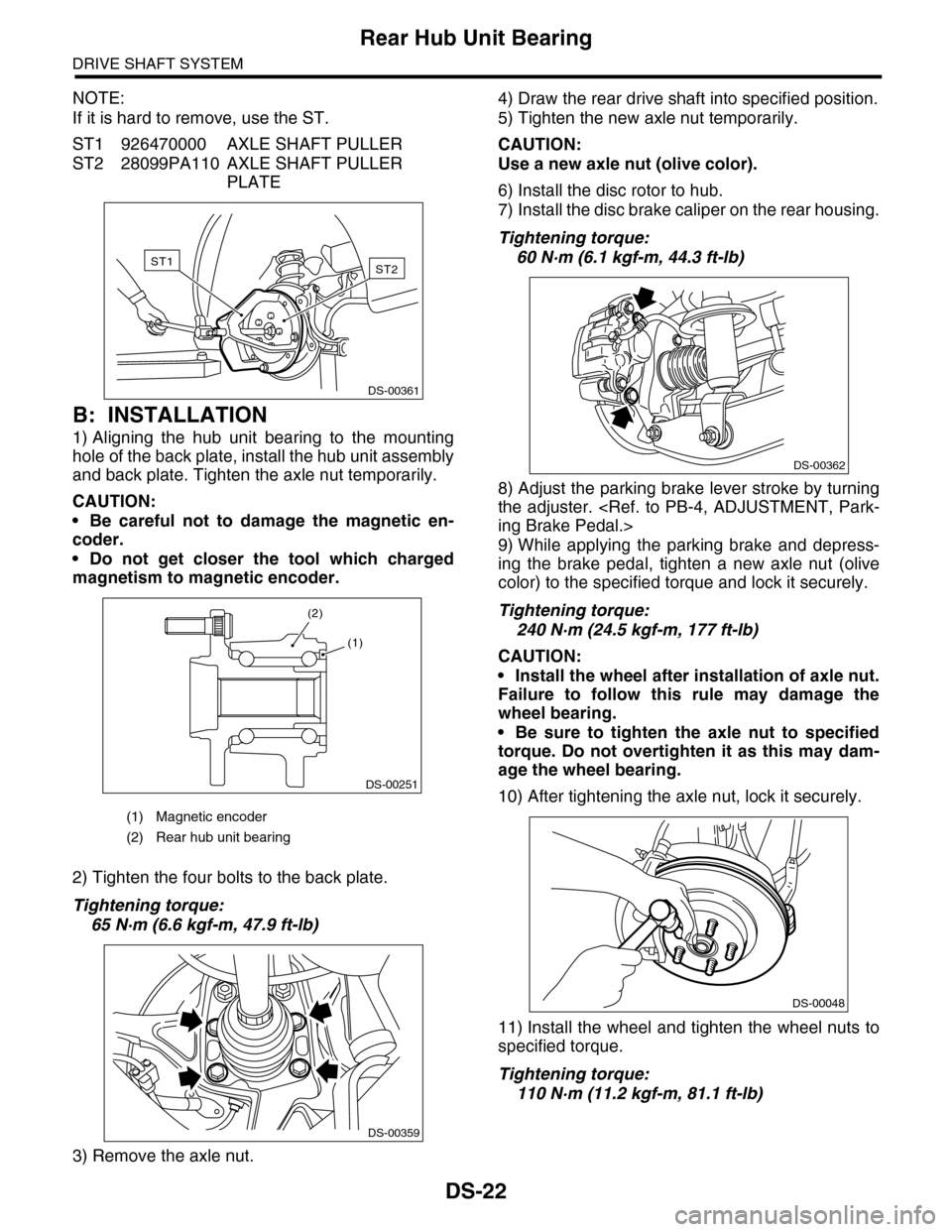
NOTE:
If it is hard to remove, use the ST.
ST1 926470000 AXLE SHAFT PULLER
ST2 28099PA110 AXLE SHAFT PULLER
PLATE
B: INSTALLATION
1) Aligning the hub unit bearing to the mounting
hole of the back plate, install the hub unit assembly
and back plate. Tighten the axle nut temporarily.
CAUTION:
•Be careful not to damage the magnetic en-
coder.
•Do not get closer the tool which charged
magnetism to magnetic encoder.
2) Tighten the four bolts to the back plate.
Tightening torque:
65 N·m (6.6 kgf-m, 47.9 ft-lb)
3) Remove the axle nut.
4) Draw the rear drive shaft into specified position.
5) Tighten the new axle nut temporarily.
CAUTION:
Use a new axle nut (olive color).
6) Install the disc rotor to hub.
7) Install the disc brake caliper on the rear housing.
Tightening torque:
60 N·m (6.1 kgf-m, 44.3 ft-lb)
8) Adjust the parking brake lever stroke by turning
the adjuster.
9) While applying the parking brake and depress-
ing the brake pedal, tighten a new axle nut (olive
color) to the specified torque and lock it securely.
Tightening torque:
240 N·m (24.5 kgf-m, 177 ft-lb)
CAUTION:
•Install the wheel after installation of axle nut.
Failure to follow this rule may damage the
wheel bearing.
•Be sure to tighten the axle nut to specified
torque. Do not overtighten it as this may dam-
age the wheel bearing.
10) After tightening the axle nut, lock it securely.
11) Install the wheel and tighten the wheel nuts to
specified torque.
Tightening torque:
110 N·m (11.2 kgf-m, 81.1 ft-lb)
(1) Magnetic encoder
(2) Rear hub unit bearing
ST2ST1
DS-00361
DS-00251
(2)
(1)
DS-00359
DS-00362
DS-00048