oil SUBARU TRIBECA 2009 1.G Service Workshop Manual
[x] Cancel search | Manufacturer: SUBARU, Model Year: 2009, Model line: TRIBECA, Model: SUBARU TRIBECA 2009 1.GPages: 2453, PDF Size: 46.32 MB
Page 4 of 2453
AB-5
General Description
AIRBAG SYSTEM
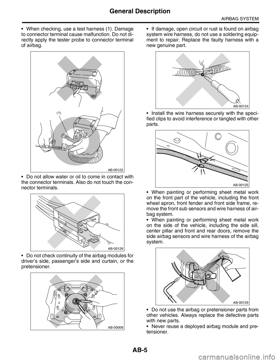
•When checking, use a test harness (1). Damage
to connector terminal cause malfunction. Do not di-
rectly apply the tester probe to connector terminal
of airbag.
•Do not allow water or oil to come in contact with
the connector terminals. Also do not touch the con-
nector terminals.
•Do not check continuity of the airbag modules for
driver’s side, passenger’s side and curtain, or the
pretensioner.
•If damage, open circuit or rust is found on airbag
system wire harness, do not use a soldering equip-
ment to repair. Replace the faulty harness with a
new genuine part.
•Install the wire harness securely with the speci-
fied clips to avoid interference or tangled with other
parts.
•When painting or performing sheet metal work
on the front part of the vehicle, including the front
wheel apron, front fender and front side frame, re-
move the front sub sensors and wire harness of air-
bag system.
•When painting or performing sheet metal work
on the side of the vehicle, including the side sill,
center pillar and front and rear doors, remove the
side airbag sensors and wire harness of the airbag
system.
•Do not use the airbag or pretensioner parts from
other vehicles. Always replace the defective parts
with new parts.
•Never reuse a deployed airbag module and pre-
tensioner.
AB-00122
(1)
AB-00126
AB-00006
AB-00124
AB-00125
AB-00129
Page 5 of 2453
AB-6
General Description
AIRBAG SYSTEM
•Do not discard the uninflated airbag or preten-
sioner.
•When airbag control module, front sub sensor,
side airbag sensor and curtain airbag sensor are
removed, do not reuse the bolts and nuts of them.
Always use new bolts and nuts for them.
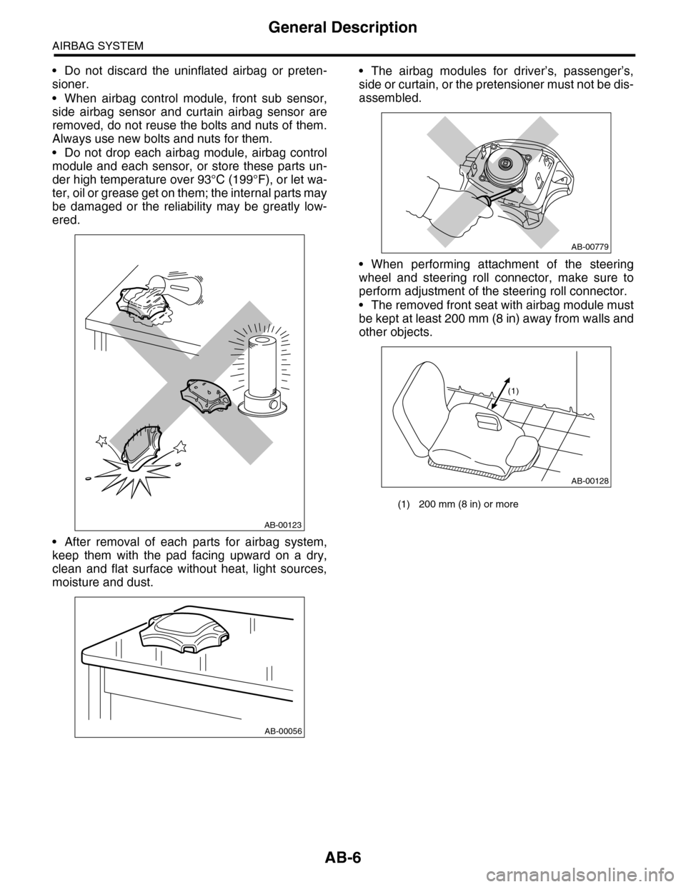
•Do not drop each airbag module, airbag control
module and each sensor, or store these parts un-
der high temperature over 93°C (199°F), or let wa-
ter, oil or grease get on them; the internal parts may
be damaged or the reliability may be greatly low-
ered.
•After removal of each parts for airbag system,
keep them with the pad facing upward on a dry,
clean and flat surface without heat, light sources,
moisture and dust.
•The airbag modules for driver’s, passenger’s,
side or curtain, or the pretensioner must not be dis-
assembled.
•When performing attachment of the steering
wheel and steering roll connector, make sure to
perform adjustment of the steering roll connector.
•The removed front seat with airbag module must
be kept at least 200 mm (8 in) away from walls and
other objects.
AB-00123
AB-00056
(1) 200 mm (8 in) or more
AB-00779
AB-00128
(1)
Page 11 of 2453
AB-12
Inspection Locations After a Collision
AIRBAG SYSTEM
3. Inspection Locations After a
Collision
A: REPLACEMENT
Replace the following parts when the airbag is de-
ployed.
1. FRONT COLLISION
1) Driver’s airbag module
2) Passenger’s airbag module
3) Driver’s seat belt (Pretensioner)
4) Passenger’s seat belt (Pretensioner)
5) Airbag control module
6) Front sub sensor (L/R)
7) Roll connector
8) Instrument panel (for integrating with passen-
ger’s airbag module)
9) Passenger side seat cushion pad and frame as-
sembly
2. SIDE COLLISION
1) Airbag control module
2) Side airbag module (operating side seat back-
rest)
3) Side airbag sensor (operating side)
4) Curtain airbag module (operating side)
5) Curtain airbag sensor (operating side)
3. INSPECTION OF OTHER PARTS
Check for the following parts, and replace the dam-
aged parts with new parts.
1) Steering wheel and steering shaft
Check the steering shaft for mounting conditions
and deflection of front and rear, upward and down-
ward directions, and deflection of front and rear di-
rection with tilt lever released. (After a collision,
there is a good chance that the shock absorbing
part of steering shaft may have operated.)
2) Check the connectors of airbag module, preten-
sioner, etc. for damage, and also check each har-
ness for pinch and connector damage. Replace the
harness as a unit if damage is found.
3) Check the seat cushion frame, backrest, seat rail
and headrest for deformation, distortion, crack, and
installing condition and play.
4) For passengers seat, replace the seat cushion
frame assembly with new one if the seat cushion
frame is deformed or cracked.
5) If there are tears or loosening in the passenger
side seat cushion cover, it may interfere with the
proper operation of the passenger detection sys-
tem. Replace with a new cushion cover.
6) Be sure to perform the system calibration for the
occupant detection system after removing or re-
placing the passenger seat cushion cover. Failure
to do so may cause improper operation of the pas-
senger detection system.
TION, Subaru Select Monitor.>
7) Use the Subaru Select Monitor to check whether
the drivers seat position sensor and the drivers and
the front left/right seat belt buckle switches are op-
erating normally.
B: INSPECTION
If the vehicle is involved in a collision, even if it is a
slight collision, be sure to check the following sys-
tems.
1. DRIVER’S AIRBAG MODULE
1) Check for the following, and replace the dam-
aged parts with new parts.
•Airbag module is cracked or deformed.
•Harness and/or connector is cracked, deformed
or open. Harness wire is exposed.
•The module surface is fouled with grease, oil,
water or cleaning solvent.
2) When installing a new driver’s airbag module,
check for the following, and replace the damaged
parts with new parts.
•The steering wheel is in the way, making it diffi-
cult to install the airbag module.
•The clearance between the driver’s airbag mod-
ule and steering wheel is not constant.
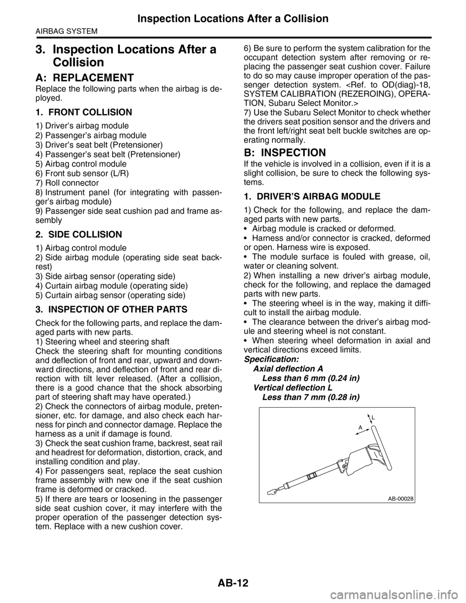
•When steering wheel deformation in axial and
vertical directions exceed limits.
Specification:
Axial deflection A
Less than 6 mm (0.24 in)
Vertical deflection L
Less than 7 mm (0.28 in)
AB-00028
L
A
Page 28 of 2453
AB(diag)-4
General Description
AIRBAG SYSTEM (DIAGNOSTICS)
3. General Description
A: CAUTION
•When servicing a vehicle, be sure to turn the ig-
nition switch to OFF, disconnect the ground cable
from battery, and wait for more than 20 seconds
before starting work.
•The airbag system is fitted with a backup power
source. After disconnecting the battery ground ca-
ble, the airbag may deploy if you do not wait for
more than 20 seconds before starting the service of
airbag system.
•If sensors, airbag module, airbag control module,
pretensioner or harness is deformed or damaged,
replace with new part.
•Do not use the airbag system and pretensioners
on other vehicles. When replacing parts, be sure to
replace them with new ones.
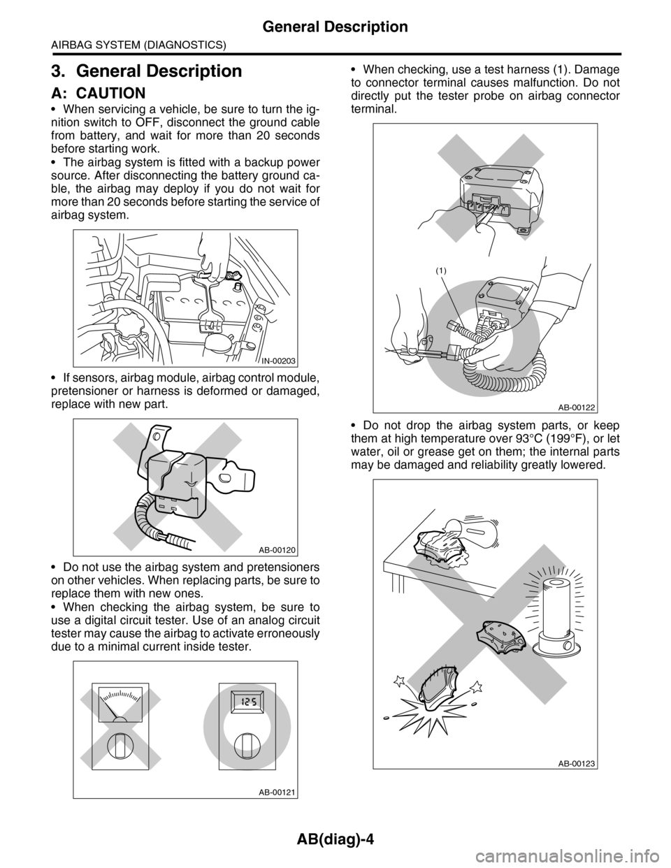
•When checking the airbag system, be sure to
use a digital circuit tester. Use of an analog circuit
tester may cause the airbag to activate erroneously
due to a minimal current inside tester.
•When checking, use a test harness (1). Damage
to connector terminal causes malfunction. Do not
directly put the tester probe on airbag connector
terminal.
•Do not drop the airbag system parts, or keep
them at high temperature over 93°C (199°F), or let
water, oil or grease get on them; the internal parts
may be damaged and reliability greatly lowered.
IN-00203
AB-00120
AB-00121
AB-00122
(1)
AB-00123
Page 29 of 2453
AB(diag)-5
General Description
AIRBAG SYSTEM (DIAGNOSTICS)
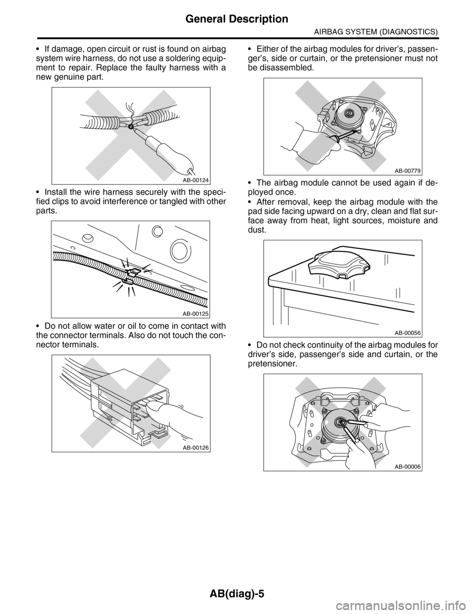
•If damage, open circuit or rust is found on airbag
system wire harness, do not use a soldering equip-
ment to repair. Replace the faulty harness with a
new genuine part.
•Install the wire harness securely with the speci-
fied clips to avoid interference or tangled with other
parts.
•Do not allow water or oil to come in contact with
the connector terminals. Also do not touch the con-
nector terminals.
•Either of the airbag modules for driver’s, passen-
ger’s, side or curtain, or the pretensioner must not
be disassembled.
•The airbag module cannot be used again if de-
ployed once.
•After removal, keep the airbag module with the
pad side facing upward on a dry, clean and flat sur-
face away from heat, light sources, moisture and
dust.
•Do not check continuity of the airbag modules for
driver’s side, passenger’s side and curtain, or the
pretensioner.
AB-00124
AB-00125
AB-00126
AB-00779
AB-00056
AB-00006
Page 189 of 2453
ET-3
Audio System
ENTERTAINMENT
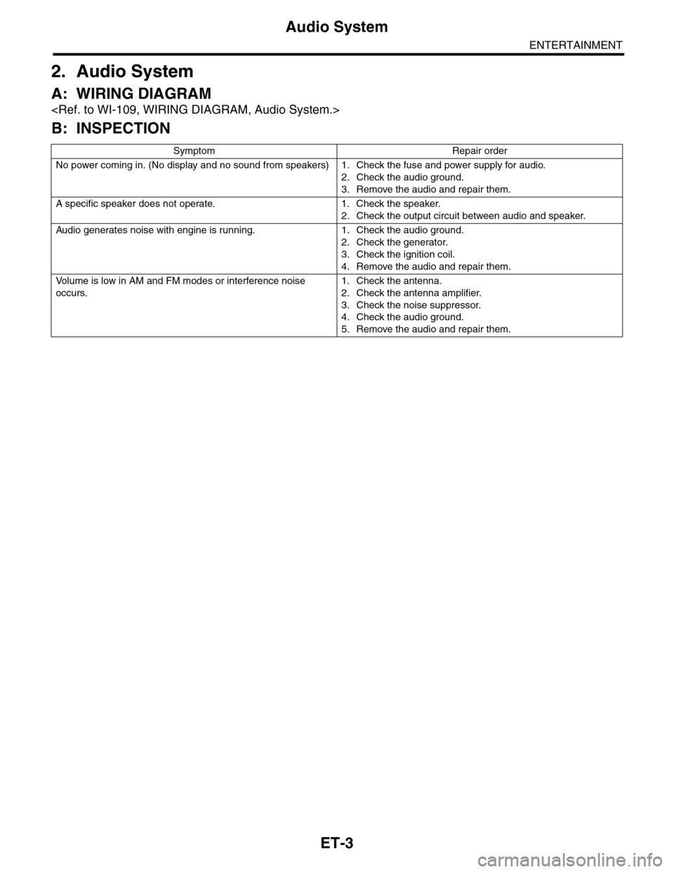
2. Audio System
A: WIRING DIAGRAM
B: INSPECTION
Symptom Repair order
No power coming in. (No display and no sound from speakers) 1. Check the fuse and power supply for audio.
2. Check the audio ground.
3. Remove the audio and repair them.
A specific speaker does not operate. 1. Check the speaker.
2. Check the output circuit between audio and speaker.
Audio generates noise with engine is r unning. 1. C heck the audio ground.
2. Check the generator.
3. Check the ignition coil.
4. Remove the audio and repair them.
Vo l u m e i s l o w i n A M a n d F M m o d e s o r i n t e r f e r e n c e n o i s e
occurs.
1. Check the antenna.
2. Check the antenna amplifier.
3. Check the noise suppressor.
4. Check the audio ground.
5. Remove the audio and repair them.
Page 204 of 2453
ET-19
Antenna
ENTERTAINMENT
14.Antenna
A: INSPECTION
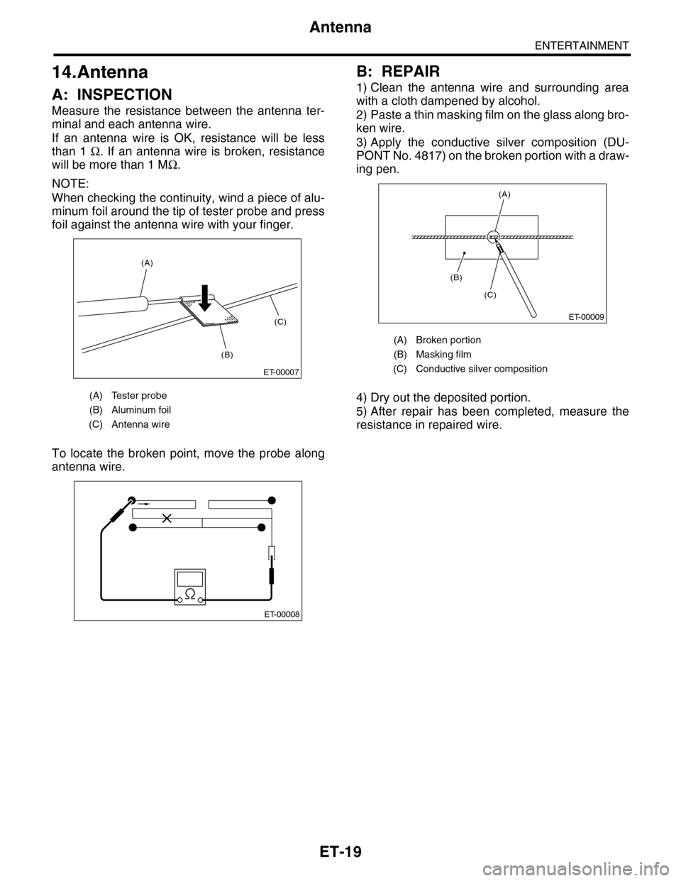
Measure the resistance between the antenna ter-
minal and each antenna wire.
If an antenna wire is OK, resistance will be less
than 1 Ω. If an antenna wire is broken, resistance
will be more than 1 MΩ.
NOTE:
When checking the continuity, wind a piece of alu-
minum foil around the tip of tester probe and press
foil against the antenna wire with your finger.
To locate the broken point, move the probe along
antenna wire.
B: REPAIR
1) Clean the antenna wire and surrounding area
with a cloth dampened by alcohol.
2) Paste a thin masking film on the glass along bro-
ken wire.
3) Apply the conductive silver composition (DU-
PONT No. 4817) on the broken portion with a draw-
ing pen.
4) Dry out the deposited portion.
5) After repair has been completed, measure the
resistance in repaired wire.
(A) Tester probe
(B) Aluminum foil
(C) Antenna wire
ET-00007
(B)
(C)
(A)
ET-00008
(A) Broken portion
(B) Masking film
(C) Conductive silver composition
ET-00009
(B)
(C)
(A)
Page 225 of 2453
EB-6
General Description
EXTERIOR BODY PANELS
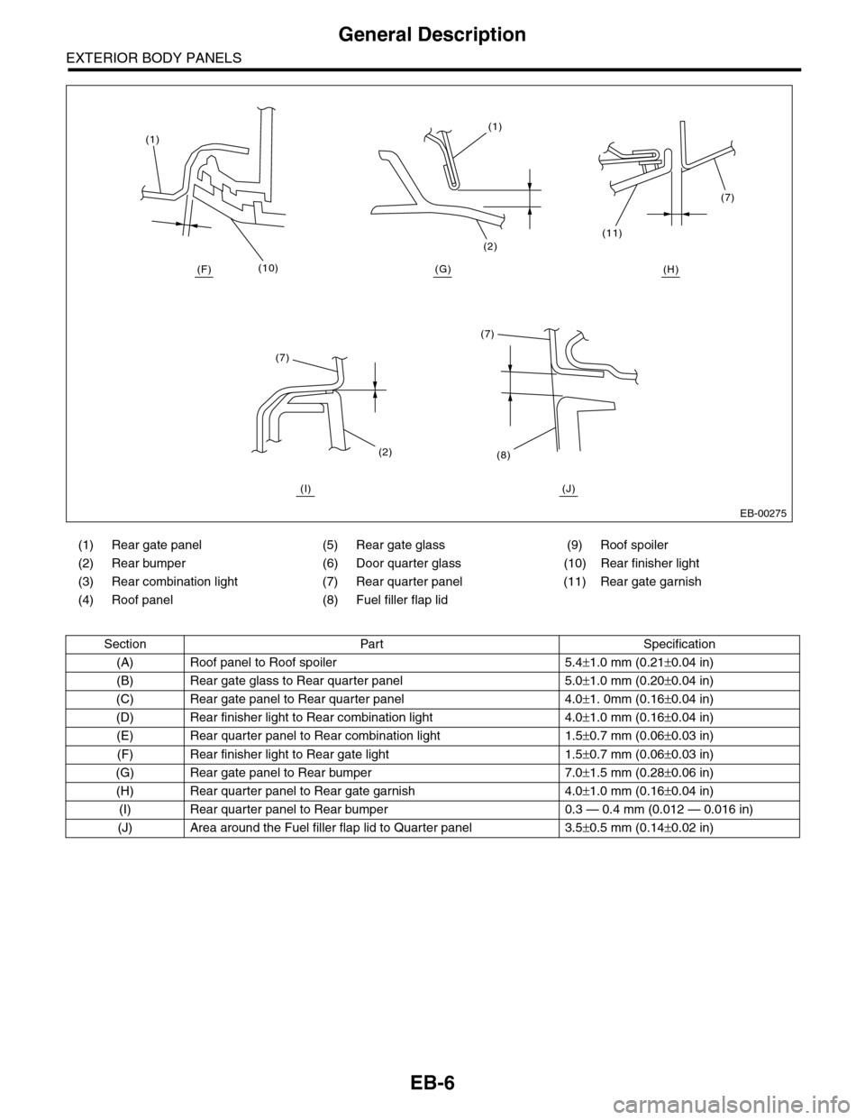
(1) Rear gate panel (5) Rear gate glass (9) Roof spoiler
(2) Rear bumper (6) Door quarter glass (10) Rear finisher light
(3) Rear combination light (7) Rear quarter panel (11) Rear gate garnish
(4) Roof panel (8) Fuel filler flap lid
Section Part Specification
(A) Roof panel to Roof spoiler 5.4±1.0 mm (0.21±0.04 in)
(B) Rear gate glass to Rear quarter panel 5.0±1.0 mm (0.20±0.04 in)
(C) Rear gate panel to Rear quarter panel 4.0±1. 0mm (0.16±0.04 in)
(D) Rear finisher light to Rear combination light 4.0±1.0 mm (0.16±0.04 in)
(E) Rear quarter panel to Rear combination light 1.5±0.7 mm (0.06±0.03 in)
(F) Rear finisher light to Rear gate light 1.5±0.7 mm (0.06±0.03 in)
(G) Rear gate panel to Rear bumper 7.0±1.5 mm (0.28±0.06 in)
(H) Rear quarter panel to Rear gate garnish 4.0±1.0 mm (0.16±0.04 in)
(I) Rear quarter panel to Rear bumper 0.3 — 0.4 mm (0.012 — 0.016 in)
(J) Area around the Fuel filler flap lid to Quarter panel 3.5±0.5 mm (0.14±0.02 in)
EB-00275
(10)
(1)(1)
(2)
(7)
(11)
(7)
(8)(2)
(7)
(H)(G)(F)
(I) (J)
Page 241 of 2453
EB-22
Rear Gate
EXTERIOR BODY PANELS
8. Rear Gate
A: REMOVAL
1. REAR GATE PANEL
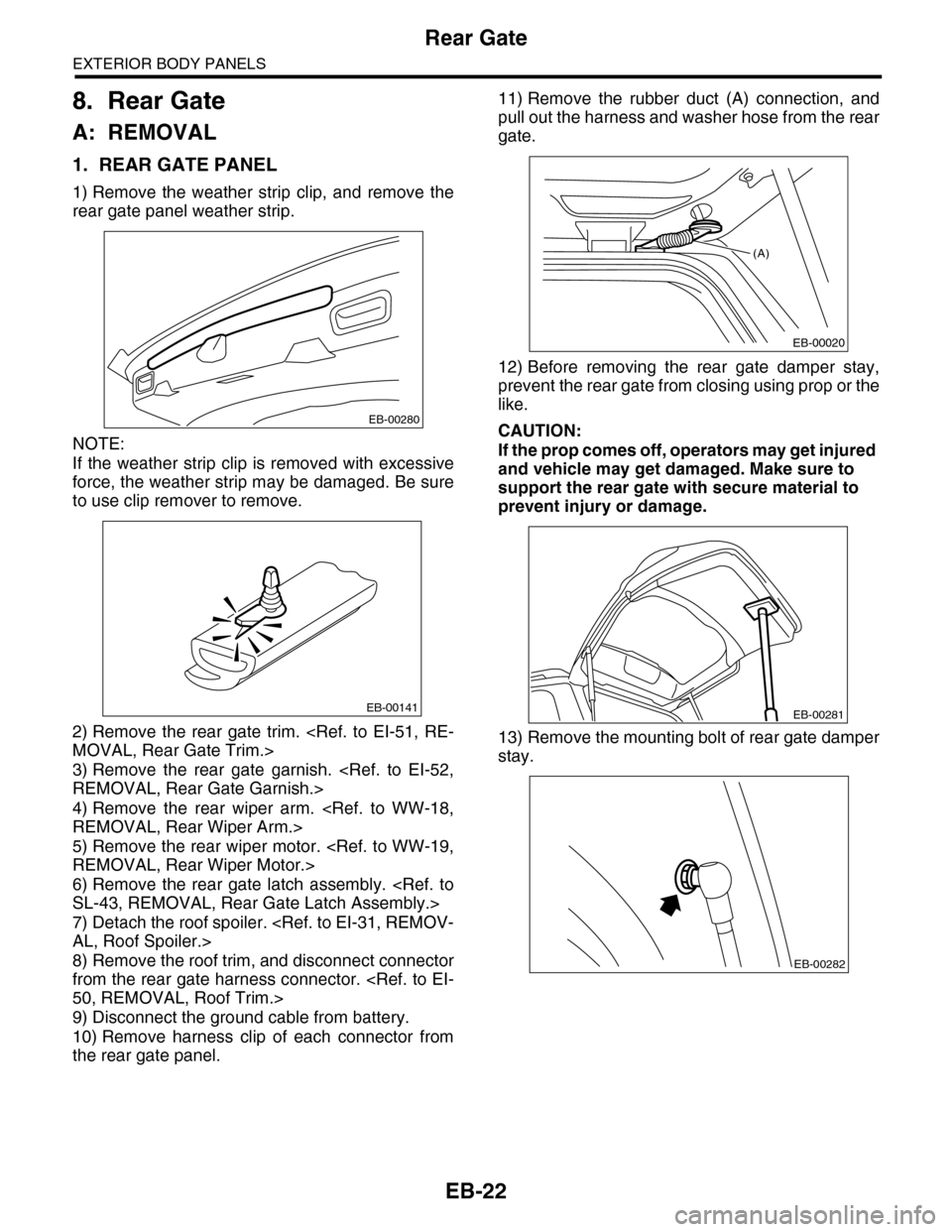
1) Remove the weather strip clip, and remove the
rear gate panel weather strip.
NOTE:
If the weather strip clip is removed with excessive
force, the weather strip may be damaged. Be sure
to use clip remover to remove.
2) Remove the rear gate trim.
3) Remove the rear gate garnish.
4) Remove the rear wiper arm.
5) Remove the rear wiper motor.
6) Remove the rear gate latch assembly.
7) Detach the roof spoiler.
8) Remove the roof trim, and disconnect connector
from the rear gate harness connector.
9) Disconnect the ground cable from battery.
10) Remove harness clip of each connector from
the rear gate panel.
11) Remove the rubber duct (A) connection, and
pull out the harness and washer hose from the rear
gate.
12) Before removing the rear gate damper stay,
prevent the rear gate from closing using prop or the
like.
CAUTION:
If the prop comes off, operators may get injured
and vehicle may get damaged. Make sure to
support the rear gate with secure material to
prevent injury or damage.
13) Remove the mounting bolt of rear gate damper
stay.
EB-00280
EB-00141
(A)
EB-00020
EB-00281
EB-00282
Page 242 of 2453
EB-23
Rear Gate
EXTERIOR BODY PANELS
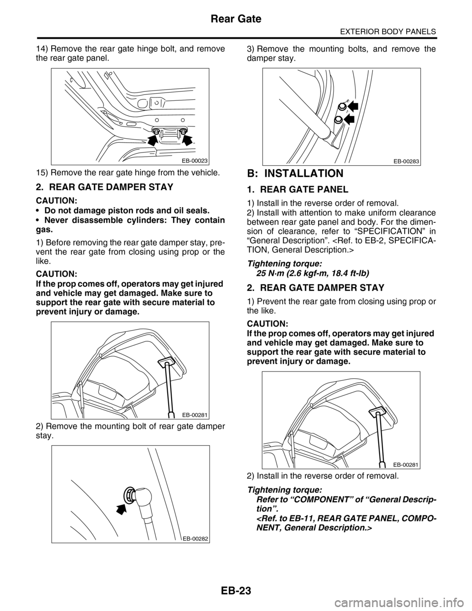
14) Remove the rear gate hinge bolt, and remove
the rear gate panel.
15) Remove the rear gate hinge from the vehicle.
2. REAR GATE DAMPER STAY
CAUTION:
•Do not damage piston rods and oil seals.
•Never disassemble cylinders: They contain
gas.
1) Before removing the rear gate damper stay, pre-
vent the rear gate from closing using prop or the
like.
CAUTION:
If the prop comes off, operators may get injured
and vehicle may get damaged. Make sure to
support the rear gate with secure material to
prevent injury or damage.
2) Remove the mounting bolt of rear gate damper
stay.
3) Remove the mounting bolts, and remove the
damper stay.
B: INSTALLATION
1. REAR GATE PANEL
1) Install in the reverse order of removal.
2) Install with attention to make uniform clearance
between rear gate panel and body. For the dimen-
sion of clearance, refer to “SPECIFICATION” in
“General Description”.
Tightening torque:
25 N·m (2.6 kgf-m, 18.4 ft-lb)
2. REAR GATE DAMPER STAY
1) Prevent the rear gate from closing using prop or
the like.
CAUTION:
If the prop comes off, operators may get injured
and vehicle may get damaged. Make sure to
support the rear gate with secure material to
prevent injury or damage.
2) Install in the reverse order of removal.
Tightening torque:
Refer to “COMPONENT” of “General Descrip-
tion”.
EB-00023
EB-00281
EB-00282
EB-00283
EB-00281