roof rack SUBARU TRIBECA 2009 1.G Service Workshop Manual
[x] Cancel search | Manufacturer: SUBARU, Model Year: 2009, Model line: TRIBECA, Model: SUBARU TRIBECA 2009 1.GPages: 2453, PDF Size: 46.32 MB
Page 19 of 2453

AB-20
Curtain Airbag Module
AIRBAG SYSTEM
C: INSPECTION
CAUTION:
Refer to “CAUTION” of “General Description”
before handling the airbag module.
Check for the following, and replace the damaged
parts with new parts.
cations After a Collision.>
1) With side collision (when curtain airbag is de-
ployed)
•Curtain airbag module assembly
•Roof Trim
•Front pillar upper trim
•Front piller pad (blue)
•Center pillar upper trim
•Center piller pad (green)
•Rear quarter upper trim
•Rear quarter piller pad (red)
•Airbag guide
2) When damage is found by visual check
•Assist grip
•Assist grip bracket
•Curtain airbag harness and connector on body
side.
3) With side collision (when curtain airbag is not de-
ployed)
Check the roof trim, pillar trim and airbag module
visually, and then replace them with new ones if
damaged or cracked.
Specially inspect the damage of airbag module
body, mounting bracket and harness connector.
4) Without side collision (dirt and damage of cover)
Replace the corresponding part with a new one.
Page 291 of 2453

EI-49
Assist Grip
EXTERIOR/INTERIOR TRIM
22.Assist Grip
A: REMOVAL
1) Remove the screw cover, and remove the screw
inside.
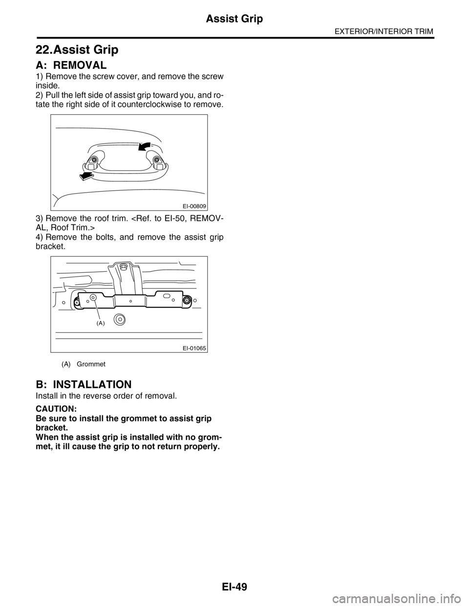
2) Pull the left side of assist grip toward you, and ro-
tate the right side of it counterclockwise to remove.
3) Remove the roof trim.
4) Remove the bolts, and remove the assist grip
bracket.
B: INSTALLATION
Install in the reverse order of removal.
CAUTION:
Be sure to install the grommet to assist grip
bracket.
When the assist grip is installed with no grom-
met, it ill cause the grip to not return properly.
(A) Grommet
EI-00809
EI-01065
(A)
Page 695 of 2453

SR-11
Sunshade
SUNROOF/T-TOP/CONVERTIBLE TOP (SUNROOF)
7. Sunshade
A: REMOVAL
1) Remove the glass lid.
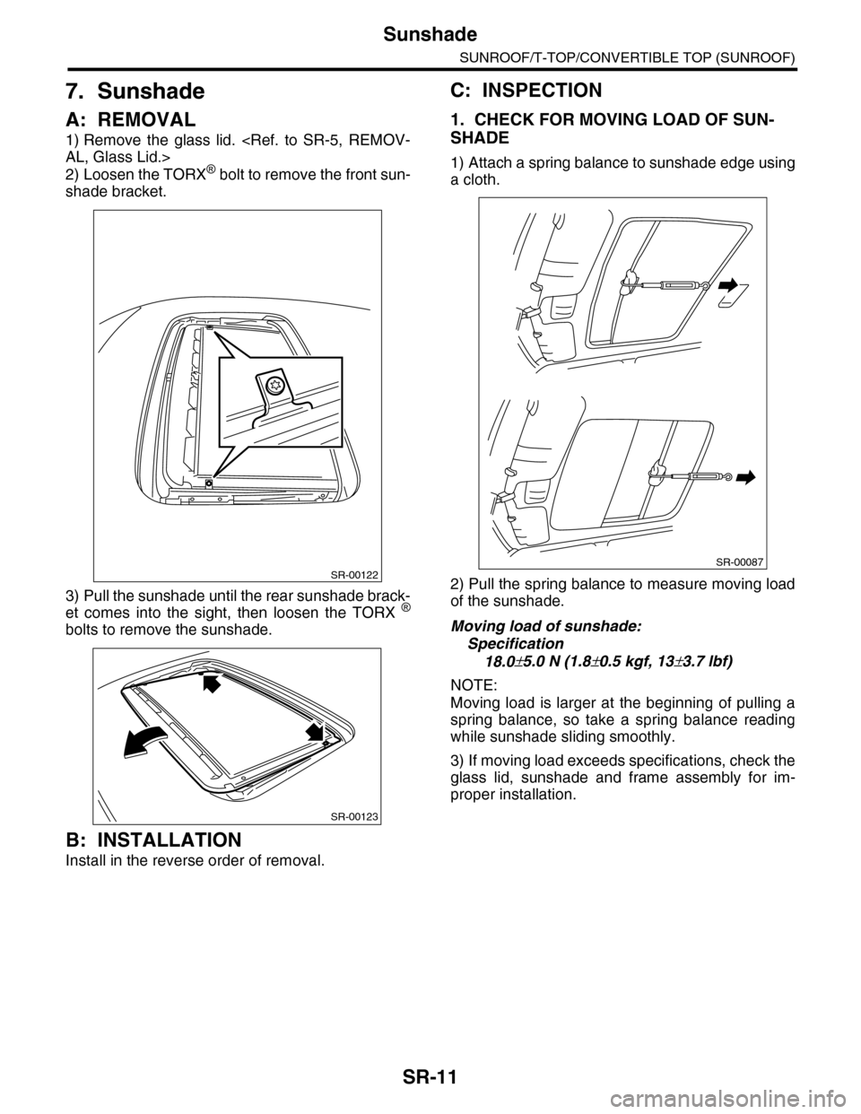
2) Loosen the TORX® bolt to remove the front sun-
shade bracket.
3) Pull the sunshade until the rear sunshade brack-
et comes into the sight, then loosen the TORX ®
bolts to remove the sunshade.
B: INSTALLATION
Install in the reverse order of removal.
C: INSPECTION
1. CHECK FOR MOVING LOAD OF SUN-
SHADE
1) Attach a spring balance to sunshade edge using
a cloth.
2) Pull the spring balance to measure moving load
of the sunshade.
Moving load of sunshade:
Specification
18.0±5.0 N (1.8±0.5 kgf, 13±3.7 lbf)
NOTE:
Moving load is larger at the beginning of pulling a
spring balance, so take a spring balance reading
while sunshade sliding smoothly.
3) If moving load exceeds specifications, check the
glass lid, sunshade and frame assembly for im-
proper installation.
SR-00122
SR-00123
SR-00087
Page 2298 of 2453

WI-14
Working Precautions
WIRING SYSTEM
2. Working Precautions
A: PRECAUTIONS WHEN WORKING
WITH THE PARTS MOUNTED ON
THE VEHICLE
1) When working under a vehicle which is jacked-
up, always be sure to use rigid rack.
2) The parking brake must always be applied dur-
ing working. Also, in automatic transmission vehi-
cles, keep the select lever set to the P (Parking)
range.
3) Be sure the workshop is properly ventilated
when running the engine. Further, be careful not to
touch the belt or fan while the engine is operating.
4) Be careful not to touch hot metal parts, especial-
ly the radiator and exhaust system immediately af-
ter the engine has been turned off.
B: PRECAUTIONS IN TROUBLE DI-
AGNOSIS AND REPAIR OF ELEC-
TRIC PARTS
1) The battery cable must be disconnected from
the battery’s (–) terminal, and the ignition switch
must be set to the OFF position, unless otherwise
required by the diagnostics.
2) Securely fasten the wiring harness with clamps
and slips so that the harness does not interfere with
the body end parts or edges and bolts or screws.
3) When installing parts, be careful not to catch
them on the wiring harness.
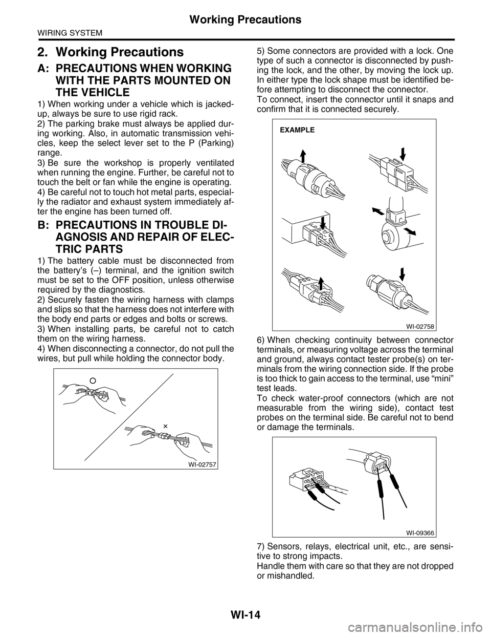
4) When disconnecting a connector, do not pull the
wires, but pull while holding the connector body.
5) Some connectors are provided with a lock. One
type of such a connector is disconnected by push-
ing the lock, and the other, by moving the lock up.
In either type the lock shape must be identified be-
fore attempting to disconnect the connector.
To connect, insert the connector until it snaps and
confirm that it is connected securely.
6) When checking continuity between connector
terminals, or measuring voltage across the terminal
and ground, always contact tester probe(s) on ter-
minals from the wiring connection side. If the probe
is too thick to gain access to the terminal, use “mini”
test leads.
To check water-proof connectors (which are not
measurable from the wiring side), contact test
probes on the terminal side. Be careful not to bend
or damage the terminals.
7) Sensors, relays, electrical unit, etc., are sensi-
tive to strong impacts.
Handle them with care so that they are not dropped
or mishandled.
WI-02757
WI-02758
EXAMPLE
WI-09366