SUBARU TRIBECA 2014 1.G Owners Manual
Manufacturer: SUBARU, Model Year: 2014, Model line: TRIBECA, Model: SUBARU TRIBECA 2014 1.GPages: 426, PDF Size: 6.37 MB
Page 291 of 426
8-12Driving tips
Loading your vehicle
WARNING
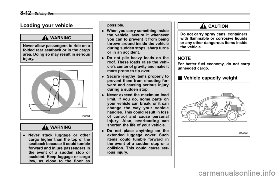
Never allow passengers to ride on afolded rear seatback or in the cargoarea. Doing so may result in seriousinjury.
WARNING
.Never stack luggage or othercargo higher than the top of theseatback because it could tumbleforward and injure passengers inthe event of a sudden stop oraccident. Keep luggage or cargolow, as close to the floor as
possible.
.When you carry something insidethe vehicle, secure it wheneveryou can to prevent it from beingthrown around inside the vehicleduring sudden stops, sharp turnsor in an accident.
.Do not pile heavy loads on theroof. These loads raise the vehi-cle’s center of gravity and make itmore prone to tip over.
.Secure lengthy items properly toprevent them from shooting for-ward and causing serious injuryduring a sudden stop.
.Never exceed the maximum loadlimit. If you do, some parts onyour vehicle can break, or it canchange the way your vehiclehandles. This could result in lossof control and cause personalinjury. Also, overloading canshorten the life of your vehicle.
.Do not place anything on theextended luggage cover. Suchitems could tumble forward inthe event of a sudden stop or acollision. This could cause ser-ious injury.
CAUTION
Do not carry spray cans, containerswith flammable or corrosive liquidsor any other dangerous items insidethe vehicle.
NOTE
For better fueleconomy, do not carryunneeded cargo.
&Vehicle capacity weight
Page 292 of 426
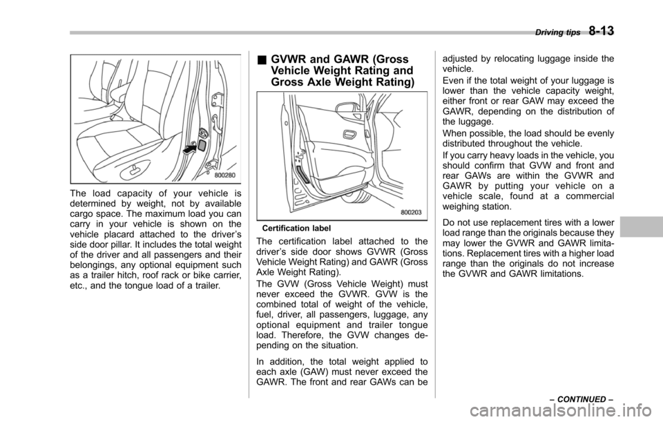
The load capacity of your vehicle isdetermined by weight, not by availablecargospace. The maximum load you cancarry in your vehicle is shown on thevehicle placard attached to the driver’sside door pillar. It includes the total weightof the driver and all passengers and theirbelongings, any optional equipment suchas a trailer hitch, roof rack or bike carrier,etc., and the tongue load of a trailer.
&GVWR and GAWR (Gross
Vehicle Weight Rating and
Gross Axle Weight Rating)
Certification label
The certification label attached to thedriver’s side door shows GVWR (GrossVehicle Weight Rating) and GAWR (GrossAxle Weight Rating).
The GVW (Gross Vehicle Weight) mustnever exceed the GVWR. GVW is thecombined total of weight of the vehicle,fuel, driver, all passengers, luggage, anyoptional equipment and trailer tongueload. Therefore, the GVW changes de-pending on the situation.
In addition, the total weight applied toeach axle (GAW) must never exceed theGAWR. The front and rear GAWs can be
adjusted by relocating luggage inside thevehicle.
Even if the total weight of your luggage islower than the vehicle capacity weight,either front or rear GAW may exceed theGAWR, depending on the distribution ofthe luggage.
When possible, the load should be evenlydistributedthroughout the vehicle.
If you carry heavy loads in the vehicle, youshould confirm that GVW and front andrearGAWs are within the GVWR andGAWR by putting your vehicle on avehicle scale, found at a commercialweighing station.
Do not use replacement tires with a lowerload range than the originals because theymay lower the GVWR and GAWR limita-tions. Replacement tires with a higher loadrange than the originals do not increasethe GVWR and GAWR limitations.
Driving tips8-13
–CONTINUED–
Page 293 of 426
8-14Driving tips
&Roof rails and crossbar (if
equipped)
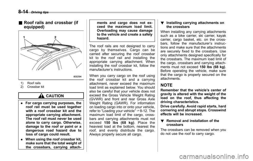
1) Roof rails2) Crossbar kit
CAUTION
.For cargo carrying purposes, theroof rail must be used togetherwith a roof crossbar kit and theappropriate carrying attachment.The roof rail must never be usedalone to carry cargo. Otherwise,damageto the roof or paint or adangerous road hazard due toloss of cargo could result.
.When using the roof crossbar kit,make sure that the total weight ofthe crossbars,carrying attach-
ments and cargo does not ex-ceed the maximum load limit.Overloading may cause damageto the vehicle and create a safetyhazard.
The roof rails are not designed to carrycargo by themselves. Cargo can becarried after securing the roof crossbarkit to the roof rail and installing theappropriate carrying attachment. Wheninstalling the roof crossbar kit, follow themanufacturer’s instructions.
When you carry cargo on the roof usingthe roof crossbar kit and a carryingattachment, never exceed the maximumload limit as explained below. You shouldalso be careful that your vehicle does notexceed the Gross Vehicle Weight Rating(GVWR) and front and rear Gross AxleWeight Rating (GAWR). For informationon loading cargo into or onto your vehicle,refer to“Loading your vehicle”F8-12. Themaximum load limit of the cargo, cross-bars and carrying attachments must notexceed150 lbs (68 kg).Placetheheaviestload at the bottom, nearest theroof, and evenly distribute the cargo.Always properly secure all cargo.
!Installing carrying attachments onthe crossbars
When installing any carrying attachmentssuch as a bike carrier, ski carrier, kayakcarrier, cargo basket, etc. on the cross-bars, follow the manufacturer’s instruc-tions and make sure that the attachmentsare securely fixed to the crossbars. Useonly attachments designed specifically forthe crossbars. The maximum load limit ofthe cargo, crossbars and carrying attach-ments must not exceed150 lbs (68 kg).Before operating the vehicle, make surethat the cargo is properly secured on theattachments.
NOTE
Remember that the vehicle’s center ofgravity is altered with the weight of theload on the roof, thus affecting thedriving characteristics.
Drive carefully. Avoid rapid starts, hardcornering and abrupt stops. Crosswindeffects will be increased.
!Removal and installation of thecrossbars
The crossbars can be removed when youdo not use the roof to carry cargo.
Page 294 of 426
!To remove the crossbar
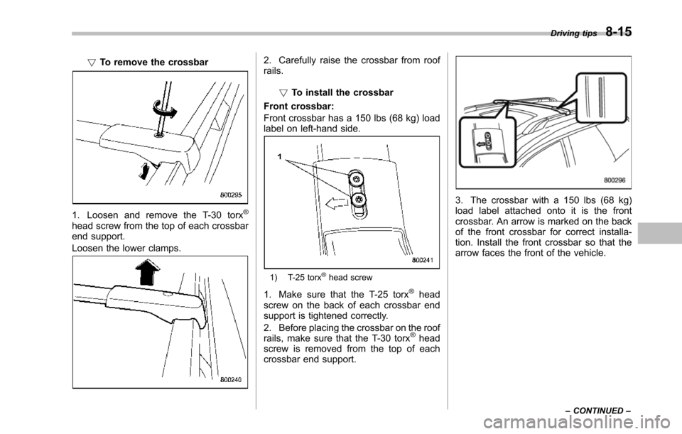
1. Loosen and remove the T-30 torx®
head screw from the top of each crossbarend support.
Loosen the lower clamps.
2. Carefully raise the crossbar from roofrails.
!To install the crossbar
Front crossbar:
Front crossbar has a 150 lbs (68 kg) loadlabel on left-hand side.
1) T-25 torx®head screw
1. Make sure that the T-25 torx®headscrew on the back of each crossbar endsupport is tightened correctly.
2. Before placing the crossbar on the roofrails, make sure that the T-30 torx®headscrew is removed from the top of eachcrossbar end support.
3. The crossbar with a 150 lbs (68 kg)load label attached onto it is the frontcrossbar. An arrow is marked on the backof the front crossbar for correct installa-tion. Install the front crossbar so that thearrow faces the front of the vehicle.
Driving tips8-15
–CONTINUED–
Page 295 of 426
8-16Driving tips
1) 6 in (150 mm)
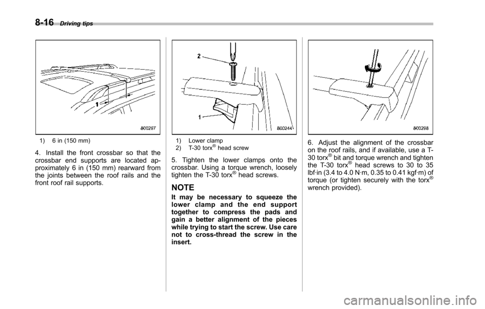
4. Install the front crossbar so that thecrossbar end supports are located ap-proximately 6 in (150 mm) rearward fromthe joints between the roof rails and thefront roof rail supports.
1) Lower clamp2) T-30 torx®head screw
5. Tighten the lower clamps onto thecrossbar. Using a torque wrench, looselytighten the T-30 torx®head screws.
NOTE
It may be necessary to squeeze thelower clamp and the end supporttogether to compress the pads andgaina better alignment of the pieceswhile trying to start the screw. Use carenot to cross-thread the screw in theinsert.
6. Adjust the alignment of the crossbaron the roof rails, and if available, use a T-30 torx®bit and torque wrench and tightenthe T-30 torx®headscrews to 30 to 35lbf·in (3.4 to 4.0 N·m, 0.35 to 0.41 kgf·m) oftorque (or tighten securely with the torx®
wrench provided).
Page 296 of 426
Rear crossbar:
1) 8 in (200 mm)
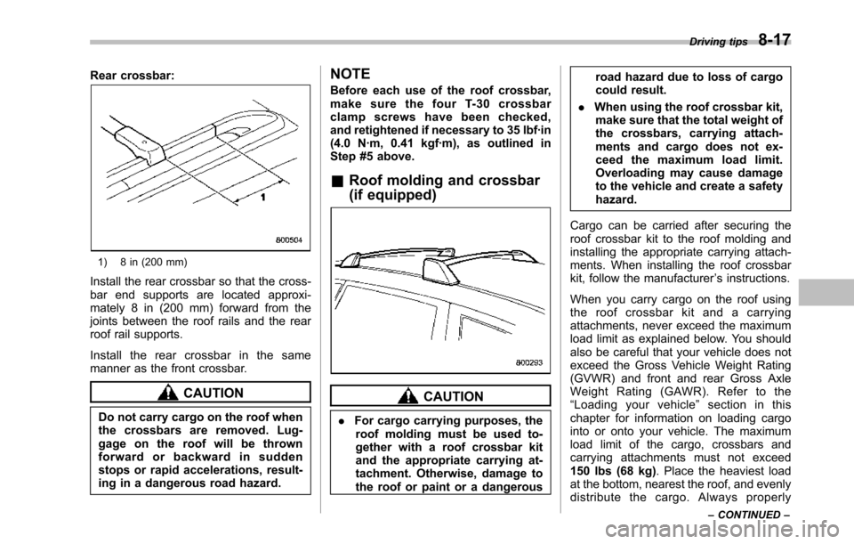
Install the rear crossbar so that the cross-bar end supports are located approxi-mately 8 in (200 mm) forward from thejoints between the roof rails and the rearroof rail supports.
Install the rear crossbar in the samemanner as the front crossbar.
CAUTION
Do not carry cargo on the roof whenthe crossbars are removed. Lug-gage on the roof will be thrownforward or backward in suddenstops or rapid accelerations, result-ing in a dangerous road hazard.
NOTE
Before each use of the roof crossbar,make sure the four T-30 crossbarclamp screws have been checked,and retightened if necessary to 35 lbf·in(4.0 N·m, 0.41 kgf·m), as outlined inStep #5 above.
&Roof molding and crossbar
(if equipped)
CAUTION
.For cargo carrying purposes, theroofmolding must be used to-gether with a roof crossbar kitand the appropriate carrying at-tachment. Otherwise, damage tothe roof or paint or a dangerous
road hazard due to loss of cargocould result.
.When using the roof crossbar kit,make sure that the total weight ofthe crossbars, carrying attach-ments and cargo does not ex-ceed the maximum load limit.Overloading may cause damageto the vehicle and create a safetyhazard.
Cargo can be carried after securing theroof crossbar kit to the roof molding andinstalling the appropriate carrying attach-ments. When installing the roof crossbarkit, follow the manufacturer’s instructions.
When you carry cargo on the roof usingthe roof crossbar kit and a carryingattachments, never exceed the maximumload limit as explained below. You shouldalso be careful that your vehicle does notexceed the Gross Vehicle Weight Rating(GVWR) and front and rear Gross AxleWeight Rating (GAWR). Refer to the“Loading your vehicle”section in thischapter for information on loading cargointo or onto your vehicle. The maximumload limit of the cargo, crossbars andcarrying attachments must not exceed150 lbs (68 kg). Place the heaviest loadat the bottom, nearest the roof, and evenlydistribute the cargo. Always properly
Driving tips8-17
–CONTINUED–
Page 297 of 426
8-18Driving tips
secure all cargo.
!Installing carrying attachments onthe crossbars
When installing any carrying attachmentssuch as a bike carrier, ski carrier, kayakcarrier, cargo basket, etc. on the cross-bars, follow the manufacturer’s instruc-tions and make sure that the attachmentsare securely fixed to the crossbars. Useonly attachments designed specifically forthe crossbars. The maximum load limit ofthe cargo,crossbars and carrying attach-ments must not exceed150 lbs (68 kg).Before operating the vehicle, make surethat the cargo is properly secured on theattachments.
NOTE
Remember that the vehicle’s center ofgravity is altered with the weight of theload on the roof, thus affecting thedriving characteristics.
Drive carefully. Avoid rapid starts, hardcornering and abrupt stops. Crosswindeffects will be increased.
!Removal and installation of thecrossbars
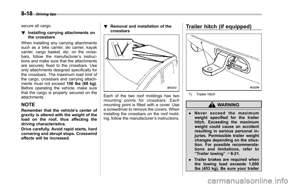
Each of the two roof moldings has twomounting points for crossbars. Eachmounting point is fitted with a cover. Usea screwdriver to remove the covers. Wheninstallingthe crossbars on the roof mold-ing, follow the manufacturer’s instructions.
Trailer hitch (if equipped)
1) Trailer hitch
WARNING
.Never exceed the maximumweight specified for the trailerhitch. Exceedingthe maximumweight could cause an accidentresulting in serious personal in-juries. Permissible trailer weightchanges depending on the situa-tion. For possible recommenda-tions and limitations, refer to“Trailer towing”F8-21.
.Trailer brakes are required whenthe towing load exceeds 1,000lbs (453 kg). Be sure your trailer
Page 298 of 426
has safety chains and that eachchain will hold the trailer’s max-imum gross weight. Towing trai-lers without safety chains couldcreate a traffic safety hazard ifthe trailer separates from thehitch due to coupling damage orhitch ball damage.
.Be sure to check the hitch pinand safety pin for positive lock-ing placement before towing atrailer. If the ball mount comes offthe hitch receiver, the trailercould get loose and create atraffic safety hazard.
.Use only the ball mount suppliedwith this hitch. Use the hitch onlyas a weight carrying hitch. Do notuse with any type of weightdistributing hitch.
The maximum gross trailer weight andmaximum gross tongue weight are indi-cated in the following table.
Maximumgross trailerweight
Maximumgross tongueweight
Vehicle with-out cooling kit2,000 lbs(906 kg)200 lbs(90 kg)
Vehicle withcooling kit3,500 lbs(1,587 kg)350 lbs(158 kg)
When you tow a trailer, follow the instruc-tions in“Trailer towing”F8-21.
&Connecting a trailer
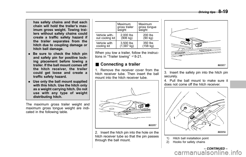
1. Remove the receiver cover from thehitch receiver tube. Then insert the ballmount into the hitch receiver tube.
2. Insert the hitch pin into the hole on thehitch receiver tube so that the pin passesthrough the ball mount.
3. Insert the safety pin into the hitch pinsecurely.
4. Pull the ball mount to make sure itdoes not come off the hitch receiver.
1) Hitch ball installation point2) Hooks for safety chains
Driving tips8-19
–CONTINUED–
Page 299 of 426
8-20Driving tips
5. Use only a hitch ball that is appropriatefor the ball mount and your trailer. Thehitch ball must be securely installed on theball mount.
6. Connect your trailer to the hitch ball.
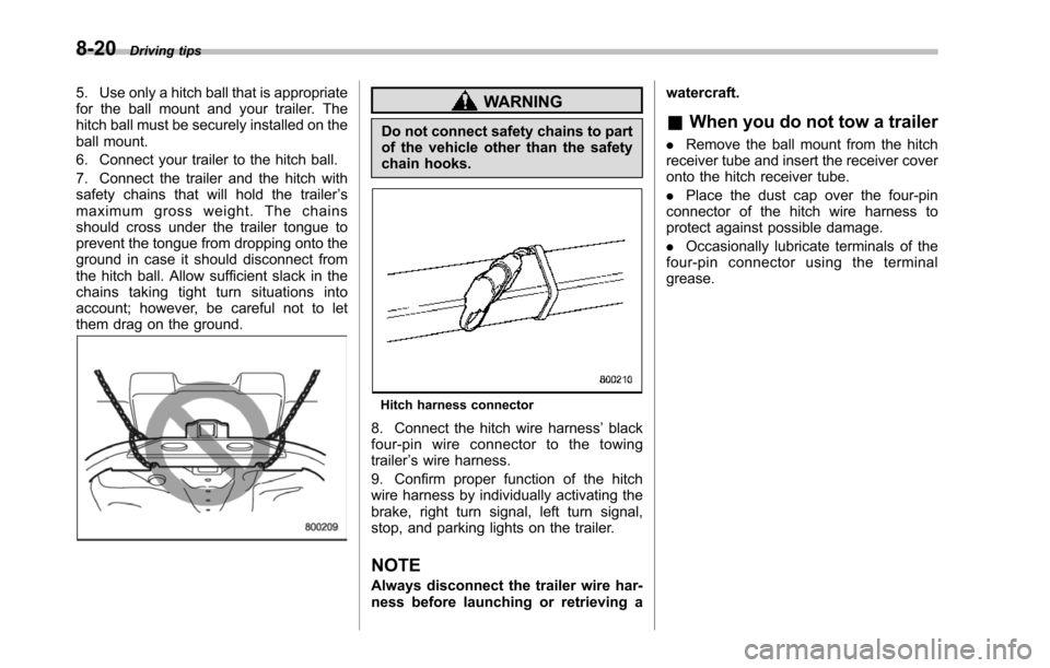
7. Connect the trailer and the hitch withsafety chains that will hold the trailer’smaximum gross weight. The chainsshould cross under the trailer tongue toprevent the tongue from dropping onto theground in case it should disconnect fromthe hitch ball. Allow sufficient slack in thechains taking tight turn situations intoaccount; however, be careful not to letthem drag on the ground.
WARNING
Do not connect safety chains to partof the vehicle other than the safetychain hooks.
Hitch harness connector
8. Connect the hitch wire harness’blackfour-pin wire connector to the towingtrailer’s wire harness.
9. Confirm proper function of the hitchwire harness by individually activating thebrake, right turn signal, left turn signal,stop,and parking lights on the trailer.
NOTE
Always disconnectthe trailer wire har-ness before launching or retrieving a
watercraft.
&When you do not tow a trailer
.Remove the ball mount from the hitchreceiver tube and insert the receiver coveronto the hitch receiver tube.
.Place the dust cap over the four-pinconnectorof the hitch wire harness toprotect against possible damage.
.Occasionally lubricate terminals of thefour-pin connector using the terminalgrease.
Page 300 of 426
Trailer towing
Your vehicle is designed and intended tobe used primarily as a passenger-carryingvehicle. Towing a trailer puts additionalloads on your vehicle’s engine, drivetrain,brakes, tires and suspension and has anadverse effect on fuel economy.
If you do decide to tow a trailer, your safetyand satisfaction depend upon proper useof correct equipment and cautious opera-tion of your vehicle. Seek the advice ofyour SUBARU dealer to assist you inpurchasing a hitch and other necessarytowing equipment appropriate for yourvehicle. In addition, be sure to follow theinstructionson correct installation and useprovided by the trailer and other towingequipment manufacturers.
SUBARUassumes no responsibility forinjuries or vehicle damage that result fromtrailer towing equipment, or from anyerrors or omissions in the instructionsaccompanying such equipment or for yourfailure to follow the proper instructions.
&Warranties and maintenance
SUBARU warranties do not apply tovehicle damage or malfunction causedby trailer towing. If you use your vehicle totow a trailer, more frequent maintenancewill be required due to the additional load.
(Refer to“Maintenance schedule undersevere driving conditions”in the“Warrantyand Maintenance Booklet”.)
Under no circumstances should a trailerbe towed with a new vehicle or a vehiclewith any new powertrain component (en-gine, transmission, differential, wheelbearings, etc.) for the first 1,000 miles(1,600 km) of driving.
&Maximum load limits
WARNING
Never exceed the maximum loadlimits explained in the following.Exceeding the maximum load limitscould cause personal injury and/orvehicle damage.
CAUTION
.Adequate size trailer brakes arerequired when the trailer and itscargo exceed1,000 lbs (453 kg)total weight.
.Before towing a trailer, check thetrailer total weight, GVW, GAWsand tongue load. Make sure theload and its distribution in yourvehicle and trailer are accepta-
ble.
!Total trailer weight
Total trailer weight
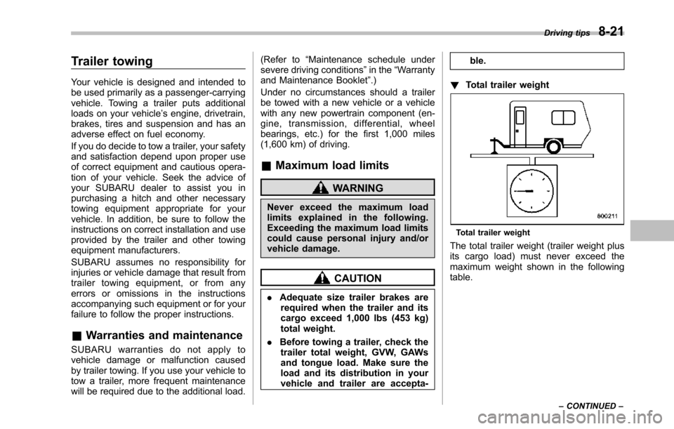
The total trailer weight (trailer weight plusits cargo load) must never exceed themaximum weight shown in the followingtable.
Driving tips8-21
–CONTINUED–