SUBARU TRIBECA 2014 1.G Owners Manual
Manufacturer: SUBARU, Model Year: 2014, Model line: TRIBECA, Model: SUBARU TRIBECA 2014 1.GPages: 426, PDF Size: 6.37 MB
Page 251 of 426
7-4Starting and operating
WARNING
Before opening the fuel filler cap,first touch the vehicle body or ametal portion of the fuel pump orsimilar object to discharge anystatic electricity that may be presenton your body. If your body is carry-ing an electrostatic charge, there isa possibility that an electric sparkcould ignite the fuel, which couldburn you. To avoid acquiring a newstatic electric charge, do not getback into the vehicle while refuelingis in progress.
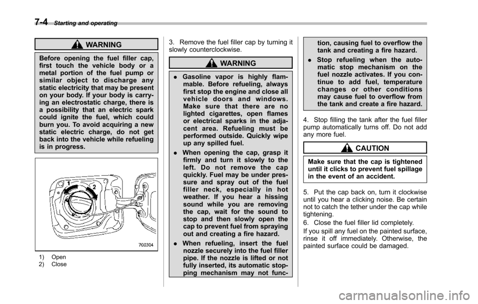
1) Open2) Close
3. Remove the fuel filler cap by turning itslowly counterclockwise.
WARNING
.Gasoline vapor is highly flam-mable. Before refueling, alwaysfirst stop the engine and close allvehicle doors and windows.Make sure that there are nolighted cigarettes, open flamesor electrical sparks in the adja-cent area. Refueling must beperformed outside. Quickly wipeup any spilled fuel.
.When opening the cap, grasp itfirmly and turn it slowly to theleft. Do not remove the capquickly. Fuel may be under pres-sure and spray out of the fuelfiller neck, especially in hotweather. If you hear a hissingsound while you are removingthe cap, wait for the sound tostop and then slowly open thecapto prevent fuel from sprayingout and creating a fire hazard.
.When refueling, insert the fuelnozzle securely into the fuel fillerpipe. If the nozzle is lifted or notfullyinserted, its automatic stop-ping mechanism may not func-
tion, causing fuel to overflow thetank and creating a fire hazard.
.Stop refueling when the auto-matic stop mechanism on thefuel nozzle activates. If you con-tinue to add fuel, temperaturechanges or other conditionsmay cause fuel to overflow fromthe tank and create a fire hazard.
4. Stop filling the tank after the fuel fillerpump automatically turns off. Do not addany more fuel.
CAUTION
Make sure that the cap is tighteneduntil it clicks to prevent fuel spillagein the event of an accident.
5. Put the cap back on, turn it clockwiseuntil you hear a clicking noise. Be certainnot to catch the tether under the cap whiletightening.
6. Close the fuel filler lid completely.
If you spill any fuel on the painted surface,rinse it off immediately. Otherwise, thepainted surface could be damaged.
Page 252 of 426
NOTE
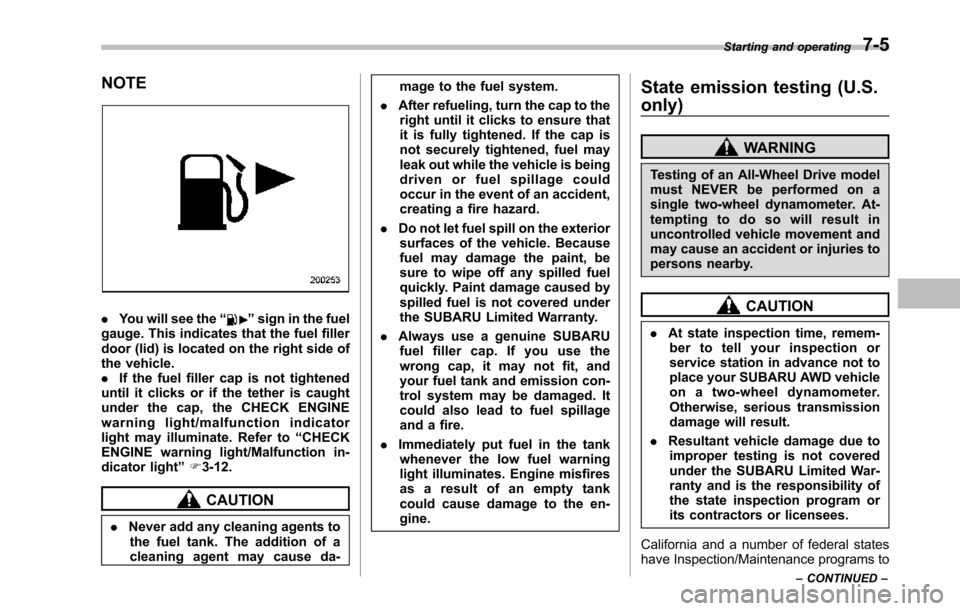
.You will see the“”sign in the fuelgauge. Thisindicates that the fuel fillerdoor (lid) is located on the right side ofthe vehicle..If the fuel filler cap is not tighteneduntil it clicks or if the tether is caughtunder the cap, the CHECK ENGINEwarning light/malfunction indicatorlight may illuminate. Refer to“CHECKENGINE warning light/Malfunction in-dicator light”F3-12.
CAUTION
.Never add any cleaning agents tothe fuel tank. The addition of acleaning agent may cause da-
mage to the fuel system.
.After refueling, turn the cap to theright until it clicks to ensure thatit is fully tightened. If the cap isnot securely tightened, fuel mayleak out while the vehicle is beingdriven or fuel spillage couldoccur in the event of an accident,creating a fire hazard.
.Do not let fuel spill on the exteriorsurfacesof the vehicle. Becausefuel may damage the paint, besure to wipe off any spilled fuelquickly. Paint damage caused byspilled fuel is not covered undertheSUBARU Limited Warranty.
.Always use a genuine SUBARUfuel filler cap. If you use thewrong cap, it may not fit, andyour fuel tank and emission con-trol systemmay be damaged. Itcould also lead to fuel spillageand a fire.
.Immediately put fuel in the tankwhenever the low fuel warninglight illuminates. Engine misfiresas a result of an empty tankcould cause damage to the en-gine.
State emission testing (U.S.
only)
WARNING
Testing of an All-Wheel Drive modelmust NEVER be performed on asingle two-wheel dynamometer. At-tempting to do so will result inuncontrolled vehicle movement andmay cause an accident or injuries topersons nearby.
CAUTION
.At state inspection time, remem-ber to tell your inspection orservice station in advance not toplace your SUBARU AWD vehicleon a two-wheel dynamometer.Otherwise, serious transmissiondamage will result.
.Resultant vehicle damage due toimproper testing is not coveredunderthe SUBARU Limited War-ranty and is the responsibility ofthe state inspection program orits contractors or licensees.
California and a number of federal stateshave Inspection/Maintenance programs to
Starting and operating7-5
–CONTINUED–
Page 253 of 426
7-6Starting and operating
inspect your vehicle’s emission controlsystem. If your vehicle does not pass thistest, some states may deny renewal ofyour vehicle’s registration.
Your vehicle is equipped with a computerthat monitors the performance of theengine’s emission control system. Certi-fied emissioninspectors will inspect theOn-Board Diagnostic (OBDII) system aspart of the state emission inspectionprocess. The OBDII system is designedto detect engine and transmission pro-blems that might cause the vehicle emis-sions to exceed allowable limits. OBDIIinspectionsapply to all 1996 model yearand newer passenger cars and trucks.Over 30 states plus the District of Colum-bia have implemented emission inspec-tion of the OBDII system.
.The inspection of the OBDII systemconsists of a visual operational check ofthe“CHECK ENGINE”warning light/mal-function indicator light (MIL) and anexamination of the OBDII system with anelectronic scan tool.
.A vehiclepasses the OBDII systeminspection if proper operation of the“CHECK ENGINE”warning light is ob-served, there are no stored diagnostictrouble codes, and the OBDII readinessmonitors are all complete.
.A vehiclefails the OBDII inspection ifthe“CHECK ENGINE”warning light is notproperly operating (light is illuminated or isnot working due to a burned out bulb) orthere is one or more diagnostic troublecodes stored in the vehicle’s computer.
.A state emission inspection may reject(not pass or fail) a vehicle if the number ofOBDII system readiness monitors“NOTREADY”is greater than one. If thevehicle’s battery has been recently re-placed or disconnected, the OBDII systeminspection may indicate that the vehicle isnot ready for the emission test. Under thiscondition, the vehicle driver should beinstructed to drive his/her vehicle for a fewdays to reset the readiness monitors andreturn for an emission re-inspection.
.Owners of rejected or failing vehiclesshould contact their SUBARU Dealer forservice.
Some states still use dynamometers intheir emission inspection program. Adynamometer is a treadmill or roller-liketesting device that allows your vehicle’swheels to turn while the vehicle remains inone place. Prior to your vehicle being puton a dynamometer, tell your emissioninspectornot to place your SUBARUAWD vehicle on a two-wheel dynam-ometer.Otherwise, serious transmis-sion damage will result.
The U.S. Environmental ProtectionAgency (EPA) and states using two-wheeldynamometers in their emission testingprogram have EXEMPTED SUBARUAWD vehicles from the portion of thetesting program that involves a two-wheeldynamometer. There are some states thatuse four-wheel dynamometers in theirtesting program. When properly used, thisequipment should not damage a SUBARUAWD vehicle.
Under no circumstances should the rearwheels be jacked off the ground, norshould the driveshaft be disconnected forstate emission testing.
Page 254 of 426
Preparing to drive
You should perform the following checksand adjustments every day before youstart driving.
1. Check that all windows, mirrors, andlights are clean and unobstructed.
2. Check the appearance and conditionof the tires. Also check tires for properinflation.
3. Look under the vehicle for any sign ofleaks.
4. Check that the hood and rear gate arefully closed.
5. Check the adjustment of the seat.
6. Check the adjustment of the insideand outside mirrors.
7. Fasten your seatbelt. Check that yourpassengers have fastened their seatbelts.
8. Check the operation of the warningand indicator lights when the ignitionswitch is turned to the“ON”position.
9. Check the gauges, indicator and warn-ing lights after starting the engine.
NOTE
Engine oil, engine coolant, brake fluid,washer fluid and other fluid levelsshould be checked daily, weekly or atfuel stops.
Starting the engine
CAUTION
.Do not operate the starter motorcontinuously for more than 10seconds. If the engine fails tostart after operating the starterfor 5 to 10 seconds, wait for 10seconds or more before tryingagain.
.If you restart the engine while thevehicle is moving, shift the selectlever into the“N”position. Donot attempt to place the selectlever of a moving vehicle into the“P”position.
1. Apply the parking brake.
2. Turn off unnecessary lights and ac-cessories.
3. Shift the select lever to the“P”or“N”position (preferably“P”position). Thestarter will only operate when the selectlever is at the“P”or“N”position.
4. Turn the ignition switch to the“ON”position and check the operation of thewarning and indicator lights. Refer to“Warning and indicator lights”F3-9.
5. Turn the ignition switch to the“START”positionwithoutdepressing the accelera-
tor pedal. Release the key immediatelyafter the engine has started.
If the engine does not start, try thefollowing.(1) Turn the ignition switch to the“LOCK”position and wait for at least10 seconds. After checking that theparking brake is firmly set, turn theignition switch to the“START”positionwhile depressing the accelerator pedalslightly (approximately a quarter of thefull stroke).Release the acceleratorpedal as soon as the engine starts.(2) If this fails to start the engine, turnthe ignition switch back to the“LOCK”position and wait for at least 10seconds.Then fully depress the accel-erator pedal and turn the ignitionswitch to the“START”position. If theengine starts, quickly release theaccelerator pedal.(3) If this fails to start the engine, turnthe ignition switch again to the“LOCK”position.After waiting for 10 secondsor longer, turn the ignition switch to the“START”position without depressingthe accelerator pedal.(4) If the engine still refuses to start,contact your nearest SUBARU dealerfor assistance.
6. Confirm that all warning and indicatorlights have turned off after the engine has
Starting and operating7-7
–CONTINUED–
Page 255 of 426
7-8Starting and operating
started. The fuel injection system auto-matically lowers the idle speed as theengine warms up.
While the engine is warming up, makesure that the select lever is at the“P”or“N”position and that the parking brake isapplied.
NOTE
.The engine may be difficult to startwhen the battery has been discon-nected and reconnected (for mainte-nance or other purposes). This diffi-culty is caused by the electronicallycontrolled throttle’sself-diagnosisfunction. To overcome it, keep theignition switch in the“ON”positionfor approximately 10 seconds beforestartingthe engine..To p r o t e c t t h e e n g i n e w h i l e t h eselect lever is in the“P”or“N”position, the engine is controlled sothat the engine speed may not becometoo high even if the accelerator pedal isdepressed hard.
Stopping the engine
WARNING
Do not stop the engine when thevehicle is moving. This will causeloss of power to the power steeringand the brakebooster, making steer-ing and braking more difficult. Itcould also result in accidental acti-vation of the“LOCK”position on theignition switch, causing the steeringwheel to lock.
The ignition switch should be turned offonly whenthe vehicle is stopped and theengine is idling.
Remote engine start system
(dealer option)
WARNING
.Do not start the engine using theremote start system in an en-closed environment (e.g. closedgarage). Prolonged operation ofa motor vehicle in an enclosedenvironment can cause a harmfulbuild-up of Carbon Monoxide.Carbon Monoxide is harmful toyour health. Exposure to highlevels of Carbon Monoxide cancause headaches, dizziness or inextreme cases unconsciousnessand/or death.
.Before performing any servicingof the vehicle, temporarily placethe remote engine start system inservice mode to prevent thesystem from unexpectedly start-ing the engine.
Page 256 of 426
&Starting your vehicle
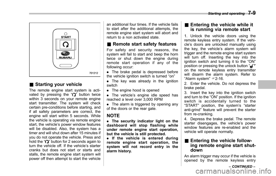
The remote engine start system is acti-vated by pressing the“”button twicewithin 3 seconds on your remote enginestart transmitter. The system will checkcertain pre-conditions before starting, andif all safety parameters are correct, theengine will start within 5 seconds. Whilethe vehicle is operating via remote enginestart, the vehicle’s power window featureswill be disabled. Also, the system has atimer and will shut down after 15 minutes ifyou do not operate the vehicle. Press andhold the“”button for 2 seconds again toturn the vehicle off. If the vehicle’s startercranks but does not start or starts andstalls, the remote engine start system willpower off then attempt to start the vehicle
an additional four times. If the vehicle failsto start after the additional attempts, theremote engine start system will abort andreturn to a non activated state.
&Remote start safety features
For safety and security reasons, thesystem will fail to start and beep the horntwice or shut down the engine duringremote start operation if any of thefollowing occur:
.The brake pedal is depressed beforethe vehicle ignition switch is turned“on”
.The key was already in the ignitionswitch
.The engine hood is opened
.The vehicle’s engine idle speed hasreached a level over 3,000 RPM
.The alarm is triggered by opening anyof the doors or the rear gate.
NOTE
.The security indicator light on thedashboard will stop flashing whileunder remote engine start operation,but the vehicle is still protected..If the vehicle is entered duringremote engine start operation, thesystem will not record entry in thealarm history.
&Entering the vehicle while it
is running via remote start
1. Unlock the vehicle doors using theremote keyless entry system. If the vehi-cle’s doors are unlocked manually usingthe key, the vehicle’s alarm system willtrigger and the remote engine start systemwill turn off. Inserting the key into theignition switch and turning it to the“ON”position or pressing the unlock button“”on the remote keyless entry transmitterwill disarm the alarm system. Refer to“Alarmsystem”F2-16.
2. Enter the vehicle. Do not depress thebrake pedal.
3. Insert the key into the ignition switchand turn to the“ON”position. If the ignitionswitch is accidentally turned to the“START”position, the system’s“starteranti-grind”feature will prevent the starterfrom re-cranking.
4. Depress the brake pedal. The remotestarter disengages, the vehicle’s powerwindow features are re-enabled and thevehicle will operate normally.
&Entering the vehicle follow-
ing remote engine start shut-
down
An alarm trigger may occur if the vehicle isopened by the remote keyless entry
Starting and operating7-9
–CONTINUED–
Page 257 of 426
7-10Starting and operating
transmitter within a few seconds immedi-ately following remote engine start shut-down.
&Pre-heating or pre-cooling
the interior of the vehicle
Before exiting the vehicle, set the tem-perature controls to the desired settingand operation. After the system starts thevehicle, the heater or air-conditioning willactivate and heat or cool the interior toyour setting.
&Service mode
In service mode, the remote start functionis temporarily disabled to prevent thesystem from unexpectedly starting theengine while being serviced.
!To engage the service mode
Turn the ignition switch to the“ON”position, depress and hold the brake pedalthen, press and release the“”button onthe remote engine start transmitter threetimes. The system will pause for 1 secondand then flash the parking lights and honkthe hornthree times indicating that thesystem is in service mode. When attempt-ing to activate the remote start systemwhile in service mode, the parking lightswill flash and the horn will honk two timesand will not start.
!To disengage the service mode
Turn the ignition switch to the“ON”position, depress and hold the brakepedal, then press and release the“”button on the remote engine start trans-mitter three times. The system will pausefor 1 second and flash the parking lightsone time indicating that the system hasexited service mode.
NOTE
When taking your vehicle in for service,it is recommended that you inform theservice personnel that your vehicle isequippedwith a remote engine startsystem.
&Remote engine start trans-
mitter programming and pro-
grammable feature option
New transmitters can be programmed tothe remote engine start system in theevent that remote engine start transmittersare lost, stolen or damaged. The remoteengine start system also has one pro-grammable feature that can be adjustedfor user preference.
The remote engine start system can beprogrammed to either make an audiblehorn chirp upon remote start activation ornot. Remote engine start transmitter pro-gramming and feature programming can
be adjusted using the following procedure.
1. Open the driver’s door (the driver’sdoor must remain opened throughout theentire process).
2. Insert the key into the vehicle’s ignitionswitch and turn to the“ON”position.
3. Locate the small black programmingbutton behind the fuse box cover, on thedriver’s side left under the dashboardpanel.
4. Press and hold the black programmingbutton for 10 to 15 seconds. The horn willhonk and the parking lights will flash threetimes to indicate that the system hasentered programming mode. At this pointyou can perform either action (step 5 orstep 6).
5. To program a remote transmitter:press and release the“”button on eachtransmitter. The horn will honk and theparking lights will flash one time to indicatea successful transmitter learn each timethe“”button is pressed. You canprogram up to eight transmitters.
6. To toggle the Horn Confirmation chirpsON/OFF: press and release the brake totoggle the feature. The horn will chirp andthe parking lights will flash one time toindicate Confirmation Horn Chirps are“OFF”. The horn will honk and the parkinglights will flash 2 times to indicate Con-firmation Horn Chirps are“ON”. Depres-
Page 258 of 426
sing the brake pedal repeatedly will togglethe feature ON or OFF each time.
7. To exit the remote transmitter andfeature programming mode, turn the igni-tion switch to the“LOCK”position, removethe key from the ignition switch and testoperation of the remote transmitter(s) andhorn confirmation feature.
&System maintenance
!Changing the batteries
CAUTION
.Do not let dust, oil or water get onor in the remote engine starttransmitter when replacing thebattery.
.Be careful not to damage theprinted circuit board in the re-mote engine start transmitterwhen replacing the battery.
.Be careful not to allow children totouch the battery and any re-moved parts; children couldswallowthem.
.There is a danger of explosion ifan incorrect replacement batteryis used. Replace only with thesame or equivalent type of bat-tery.
.Batteries should not be exposedto excessive heat such as sun-shine, fire or the like.
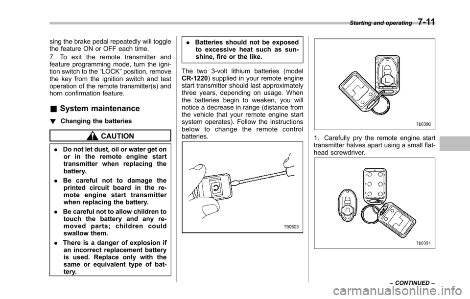
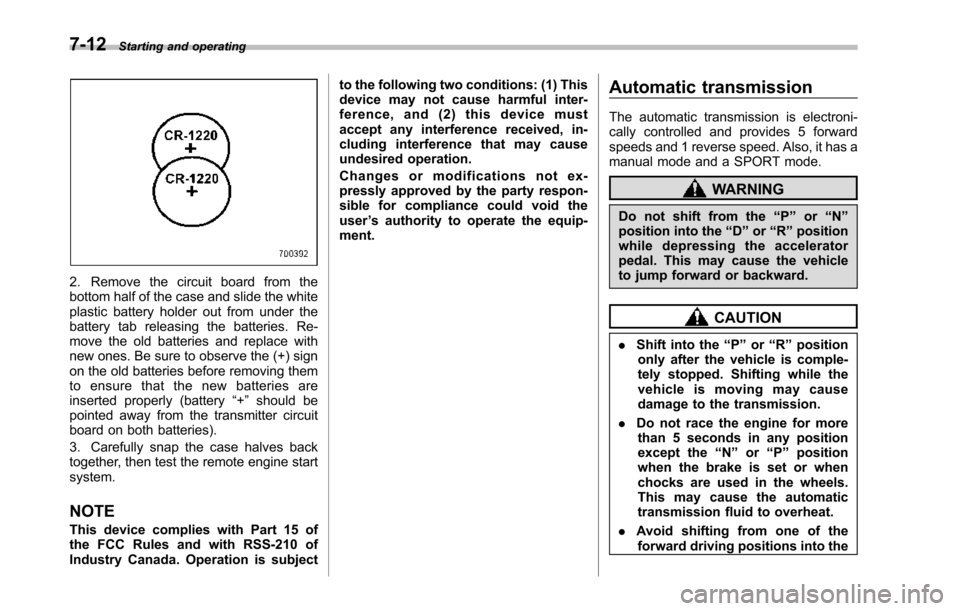
The two 3-volt lithium batteries (modelCR-1220) supplied in your remote enginestart transmitter should last approximatelythree years, depending on usage. Whenthebatteries begin to weaken, you willnotice a decrease in range (distance fromthe vehicle that your remote engine startsystem operates). Follow the instructionsbelow to change the remote controlbatteries.1. Carefully pry the remote engine starttransmitter halves apart using a small flat-head screwdriver.
Starting and operating7-11
–CONTINUED–
Page 259 of 426
7-12Starting and operating
2. Remove the circuit board from thebottom half of the case and slide the whiteplastic battery holder out from under thebattery tab releasing the batteries. Re-move the old batteries and replace withnew ones. Be sure to observe the (+) signon the old batteries before removing themto ensure that the new batteries areinserted properly (battery“+”should bepointed away from the transmitter circuitboard on both batteries).
3. Carefully snap the case halves backtogether, then test the remote engine startsystem.
NOTE
This device complies with Part 15 ofthe FCC Rules and with RSS-210 ofIndustry Canada. Operation is subject
to the following two conditions: (1) Thisdevice may not cause harmful inter-ference, and (2) this device mustaccept any interference received, in-cluding interference that may causeundesired operation.
Changes or modifications not ex-pressly approved by the party respon-sible for compliance could void theuser’s authority to operate the equip-ment.
Automatic transmission
The automatic transmission is electroni-cally controlled and provides 5 forwardspeeds and 1 reverse speed. Also, it has amanual mode and a SPORT mode.
WARNING
Do not shift from the“P”or“N”position into the“D”or“R”positionwhile depressing the acceleratorpedal.This may cause the vehicleto jump forward or backward.
CAUTION
.Shift into the“P”or“R”positiononly after the vehicle is comple-tely stopped. Shifting while thevehicle is moving may causedamage to the transmission.
.Do not race the engine for morethan 5 seconds in any positionexcept the“N”or“P”positionwhen the brake is set or whenchocks are used in the wheels.This may cause the automatictransmission fluid to overheat.
.Avoid shifting from one of theforward driving positions into the
Page 260 of 426
“R”position or vice versa untilthe vehicle has completelystopped. Such shifting maycause damage to the transmis-sion.
.When parking the vehicle, firstsecurely apply the parking brakeand then place the select lever inthe“P”position. Avoid parkingfor a long time with the selectlever in any other position asdoing so could result in a deadbattery.
NOTE
.When the engine coolant tempera-ture is still low, the automatic transmis-sion will upshift to higher enginespeeds than when the coolant tempera-ture is sufficiently high in order toshorten the warm-up time and improvedriveability. The gearshift timing willautomatically shift to the normal timingafter the engine has warmed up..Immediately after ATF (automatictransmission fluid) is replaced, youmay feel that the automatic transmis-sion operation is somewhat unusual.This results from invalidation of datawhich the on-board computer hascollected and stored in memory to
allow the transmission to shift at themost appropriate times for the currentcondition of your vehicle. Optimizedshifting will be restored as the vehiclecontinues to be driven for a while.
&Select lever
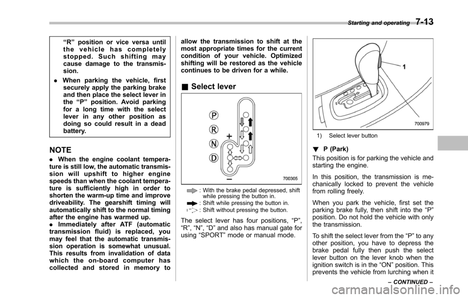
: With the brake pedal depressed, shiftwhile pressingthe button in.: Shift while pressing the button in.: Shift without pressing the button.
The select lever has four positions,“P”,“R”,“N”,“D”and also has manual gate forusing“SPORT”mode or manual mode.
1) Select lever button
!P (Park)
This position is for parking the vehicle andstarting the engine.
In this position, the transmission is me-chanically locked to prevent the vehiclefrom rolling freely.
When you park the vehicle, first set theparking brake fully, then shift into the“P”position. Do not hold the vehicle with onlythe transmission.
To shift the select lever from the“P”to anyother position, you have to depress thebrake pedal fully then push the selectlever button on the lever knob when theignition switch is in the“ON”position. Thisprevents the vehicle from lurching when it
Starting and operating7-13
–CONTINUED–