fuel pump SUBARU WRX 2016 Owners Manual
[x] Cancel search | Manufacturer: SUBARU, Model Year: 2016, Model line: WRX, Model: SUBARU WRX 2016Pages: 594, PDF Size: 19.43 MB
Page 393 of 594
Starting and operating/Fuel
! MMT
Some gasoline contains an octane-en-
hancing additive called MMT (Methylcy-
clopentadienyl Manganese Tricarbonyl). If
you use such fuels, your emission control
system performance may deteriorate and
the CHECK ENGINE warning light/Mal-
function indicator light may turn on. If this
happens, return to your authorized
SUBARU Dealer for service. If it is
determined that the condition is caused
by the type of fuel used, repairs may not
be covered by your warranty.
! Gasoline for cleaner air
Your use of gasoline with detergent
additives will help prevent deposits from
forming in your engine and fuel system.
This helps keep your engine in tune and
your emission control system working
properly, and is a way of doing your part
for cleaner air. If you continuously use a
high quality fuel with the proper detergent
and other additives, you should never
need to add any fuel system cleaning
agents to your fuel tank.
Many gasolines are now blended with
materials called oxygenates. Use of these
fuels can also help keep the air cleaner.
Oxygenated blend fuels, such as MTBE
(Methyl Tertiary Butyl ether) or ethanol
(ethyl or grain alcohol) may be used in your vehicle, but should contain no more
than 15% MTBE or 10% ethanol for the
proper operation of your SUBARU.
Do not use any gasoline that contains
more than 10% ethanol, including from
any pump labeled E15, E30, E50 or E85
(which are only some examples of fuel
containing more than 10% ethanol).
In addition, some gasoline suppliers are
now producing reformulated gasolines,
which are designed to reduce vehicle
emissions. SUBARU approves the use of
reformulated gasoline.
If you are not sure what the fuel contains,
you should ask your service station
operators if their gasolines contain deter-
gents and oxygenates and if they have
been reformulated to reduce vehicle emis-
sions.
As additional guidance, only use fuels
suited for your vehicle as explained in the
following description.
. Fuel should be unleaded and have an
octane rating no lower than that specified
in this manual.
. Methanol (methyl or wood alcohol) is
sometimes mixed with unleaded gasoline.
Methanol can be used in your vehicle
ONLY if it does not exceed 5% of the fuel
mixture AND if it is accompanied by sufficient quantities of the proper cosol-
vents and corrosion inhibitors required to
prevent damage to the fuel system. Do not
use fuel containing methanol EXCEPT
under these conditions.
. If undesirable driveability problems are
experienced and you suspect they may be
fuel related, try a different brand of gaso-
line before seeking service at your
SUBARU dealer.
. Fuel system damage or driveability
problems which result from the use of
improper fuel are not covered under the
SUBARU Limited Warranty.
CAUTIONDo not let fuel spill on the exterior
surfaces of the vehicle. Fuels con-
taining alcohol may cause paint
damage, which is not covered under
the SUBARU Limited Warranty.7-4
Page 394 of 594
& Fuel filler lid and cap ! Refueling
Only one person should be involved in
refueling. Do not allow others to approach
the area of the vehicle near the fuel filler
pipe while refueling is in progress.
Be sure to observe any other precautions
that are posted at the service station.
1. To open the fuel filler lid, pull the lid
release lever up. The lever is on the floor
at the left of the driver ’ s seat.
WARNINGBefore opening the fuel filler cap,
first touch the vehicle body or a
metal portion of the fuel pump or
similar object to discharge any
static electricity that may be present
on your body. If your body is carry-
ing an electrostatic charge, there is
a possibility that an electric spark
could ignite the fuel, which could
burn you. To avoid acquiring a new
static electric charge, do not get
back into the vehicle while refueling
is in progress. 1) Open
2) Close
2. Remove the fuel filler cap by turning it
slowly counterclockwise.
WARNING
. Gasoline vapor is highly flam-
mable. Before refueling, always
first stop the engine and close all
vehicle doors and windows.
Make sure that there are no
lighted cigarettes, open flames
or electrical sparks in the adja-
cent area. Only handle fuel out-
doors. Quickly wipe up any
spilled fuel.
. When opening the cap, grasp it
firmly and turn it slowly to the Starting and operating/Fuel
– CONTINUED –7-5
Page 395 of 594
Starting and operating/Fuel
left. Do not remove the cap
quickly. Fuel may be under pres-
sure and spray out of the fuel
filler neck, especially in hot
weather. If you hear a hissing
sound while you are removing
the cap, wait for the sound to
stop and then slowly open the
cap to prevent fuel from spraying
out and creating a fire hazard.
3. Set the fuel filler cap on the cap holder
inside the fuel filler lid.
WARNING
. When refueling, insert the fuel
nozzle securely into the fuel filler
pipe. If the nozzle is lifted or not
fully inserted, its automatic stop- ping mechanism may not func-
tion, causing fuel to overflow the
tank and creating a fire hazard.
. Stop refueling when the auto-
matic stop mechanism on the
fuel nozzle activates. If you con-
tinue to add fuel, temperature
changes or other conditions
may cause fuel to overflow from
the tank and create a fire hazard.
4. Stop filling the tank after the fuel filler
pump automatically stops. Do not add any
more fuel.
5. Put the cap back on, turn it clockwise
until you hear a clicking noise. Be certain
not to catch the tether under the cap while
tightening.
CAUTION
Make sure that the cap is tightened
until it clicks to prevent fuel spillage
in the event of an accident.
6. Close the fuel filler lid completely.
CAUTION
If you spill any fuel on the painted
surface, rinse it off immediately.
Otherwise, the painted surface could be damaged.
NOTE . You will see the “ ” sign in the fuel
gauge. This indicates that the fuel filler
door (lid) is located on the right side of
the vehicle.
. If the fuel filler cap is not tightened
until it clicks or if the tether is caught
under the cap, the CHECK ENGINE
warning light/malfunction indicator
light may illuminate. Refer to “ CHECK
ENGINE warning light/Malfunction in-
dicator light ” F 3-16.
CAUTION. Never add any cleaning agents to
the fuel tank. The addition of a
cleaning agent may cause da-
mage to the fuel system.
. After refueling, turn the cap
clockwise until it clicks to ensure
that it is fully tightened. If the cap
is not securely tightened, fuel
may leak out while the vehicle is
being driven or fuel spillage
could occur in the event of an
accident, creating a fire hazard.
. Do not let fuel spill on the exterior7-6
Page 455 of 594
Driving tips/New vehicle break – in driving – the first 1,000 miles (1,600 km)
New vehicle break-in driving
– the first 1,000 miles (1,600
km) The performance and long life of your
vehicle are dependent on how you handle
and care for your vehicle while it is new.
Follow these instructions during the first
1,000 miles (1,600 km):
. Do not race the engine. And do not
allow engine speed to exceed 4,000 rpm
except in an emergency.
. Do not drive at one constant engine or
vehicle speed for a long time, either fast or
slow.
. Avoid starting suddenly and rapid
acceleration, except in an emergency.
. Avoid hard braking, except in an
emergency.
The same break-in procedures should be
applied to an overhauled engine, newly
mounted engine or when brake pads or
brake linings are replaced with new ones. Fuel economy hints The following suggestions will help to save
fuel.
. Select the proper gear position for the
speed and road conditions.
. Avoid sudden acceleration or decelera-
tion. Always accelerate gently until you
reach the desired speed. Then try to
maintain that speed for as long as
possible.
. Do not pump the accelerator and avoid
racing the engine.
. Avoid unnecessary engine idling.
. Keep the engine properly tuned.
. Keep the tires inflated to the correct
pressure shown on the tire placard, which
is located under the door latch on the
driver ’ s side. Low pressure will increase
tire wear and fuel consumption.
. Use the air conditioner only when
necessary.
. Keep the front and rear wheels in
proper alignment.
. Avoid carrying unnecessary luggage or
cargo.
. The indication of the ECO gauge
shows a reference for saving fuel. For
details, refer to “ ECO gauge ” F 3-12.Engine exhaust gas (carbon
monoxide) WARNING. Never inhale engine exhaust gas.
Engine exhaust gas contains
carbon monoxide, a colorless
and odorless gas which is dan-
gerous, or even lethal, if inhaled.
. Always properly maintain the en-
gine exhaust system to prevent
engine exhaust gas from enter-
ing the vehicle.
. Never run the engine in a closed
space, such as a garage, except
for the brief time needed to drive
the vehicle in or out of it.
. Avoid remaining in a parked
vehicle for a lengthy time while
the engine is running. If that is
unavoidable, then use the venti-
lation fan to force fresh air into
the vehicle.
. Always keep the front ventilator
inlet grille free from snow, leaves
or other obstructions to ensure
that the ventilation system al-
ways works properly.
. If at any time you suspect that8-2
Page 479 of 594
In case of emergency/Towing
After towing, remove the towing hook from
the vehicle and stow it in the tool bucket.
Fit the towing hook cover on the bumper.
WARNINGDo not use the towing hook except
when towing your vehicle.
Be sure to remove the towing hook
after towing. Leaving the towing
hook mounted on the vehicle could
interfere with proper operation of
the fuel pump shut off function
when the vehicle is struck from
behind.
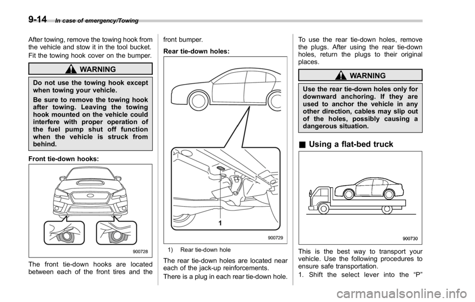
Front tie-down hooks:
The front tie-down hooks are located
between each of the front tires and the front bumper.
Rear tie-down holes:
1) Rear tie-down hole
The rear tie-down holes are located near
each of the jack-up reinforcements.
There is a plug in each rear tie-down hole. To use the rear tie-down holes, remove
the plugs. After using the rear tie-down
holes, return the plugs to their original
places.
WARNINGUse the rear tie-down holes only for
downward anchoring. If they are
used to anchor the vehicle in any
other direction, cables may slip out
of the holes, possibly causing a
dangerous situation.
& Using a flat-bed truck
This is the best way to transport your
vehicle. Use the following procedures to
ensure safe transportation.
1. Shift the select lever into the “ P ”9-14
Page 483 of 594
In case of emergency/Moonroof – if the moonroof does not close
Moonroof (if equipped) – if
the moonroof does not close If the moonroof does not close, we
recommend that you have the system
checked by a SUBARU dealer.
If your vehicle is involved in
an accident CAUTIONIf your vehicle is involved in an
accident, be sure to inspect the
ground under the vehicle before
restarting the engine. If you find that
fuel has leaked on the ground, do
not try to restart the engine. The fuel
system has been damaged and is in
need of repair. Immediately contact
the nearest automotive service facil-
ity. We recommend that you consult
your SUBARU dealer.
Your vehicle has a fuel pump shut off
system. To minimize the risk of fire due to
fuel leakage when the engine stalls or an
airbag inflates upon collision, the system
stops supplying fuel to the engine.
Perform the following procedures to re-
start the engine after the system is
activated.
Models without “ keyless access with
push-button start system ” :
1. Turn the ignition switch to the “ LOCK ”
or “ ACC ” position.
2. Restart the engine. Models with “ keyless access with
push-button start system ” :
1. Turn the push-button ignition switch to
the “ ACC ” or “ OFF ” position.
2. Restart the engine.
9-18
Page 553 of 594
Specifications/Fuses and circuits
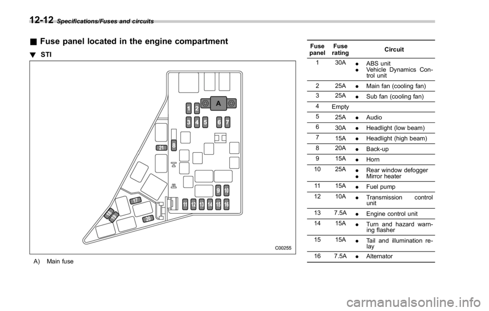
& Fuse panel located in the engine compartment! STI
A) Main fuse Fuse
panel Fuse
rating Circuit
1 30A
. ABS unit
. Vehicle Dynamics Con-
trol unit
2 25A
. Main fan (cooling fan)
3 25A
. Sub fan (cooling fan)
4
Empty
5
25A
. Audio
6
30A
. Headlight (low beam)
7
15A
. Headlight (high beam)
8 20A
. Back-up
9 15A
. Horn
10 25A
. Rear window defogger
. Mirror heater
11 15A
. Fuel pump
12 10A
. Transmission control
unit
13 7.5A
. Engine control unit
14 15A
. Turn and hazard warn-
ing flasher
15 15A
. Tail and illumination re-
lay
16 7.5A
. Alternator12-12
Page 555 of 594
Specifications/Fuses and circuits
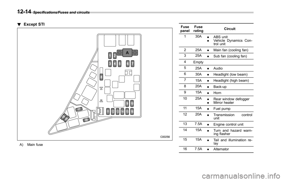
! Except STI
A) Main fuse Fuse
panel Fuse
rating Circuit
1 30A
. ABS unit
. Vehicle Dynamics Con-
trol unit
2 25A
. Main fan (cooling fan)
3 25A
. Sub fan (cooling fan)
4
Empty
5
25A
. Audio
6
30A
. Headlight (low beam)
7
15A
. Headlight (high beam)
8 20A
. Back-up
9 15A
. Horn
10 25A
. Rear window defogger
. Mirror heater
11 15A
. Fuel pump
12 20A
. Transmission control
unit
13 7.5A
. Engine control unit
14 15A
. Turn and hazard warn-
ing flasher
15 15A
. Tail and illumination re-
lay
16 7.5A
. Alternator12-14