light SUZUKI BALENO 1999 1.G Owners Manual
[x] Cancel search | Manufacturer: SUZUKI, Model Year: 1999, Model line: BALENO, Model: SUZUKI BALENO 1999 1.GPages: 65, PDF Size: 3.28 MB
Page 2 of 65
60G-74E
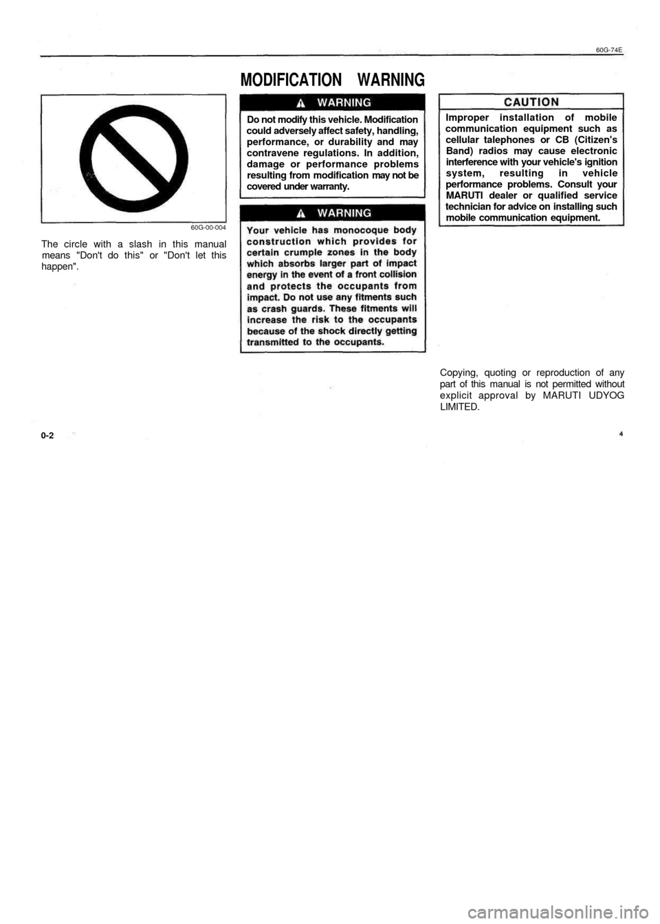
MODIFICATION WARNING
60G-00-004
The circle with a slash in this manual
means "Don't do this" or "Don't let this
happen".
Do not modify this vehicle. Modification
could adversely affect safety, handling,
performance, or durability and may
contravene regulations. In addition,
damage or performance problems
resulting from modification may not be
covered under warranty.
Improper installation of mobile
communication equipment such as
cellular talephones or CB (Citizen's
Band) radios may cause electronic
interference with your vehicle's ignition
system, resulting in vehicle
performance problems. Consult your
MARUTI dealer or qualified service
technician for advice on installing such
mobile communication equipment.
0-2
Copying, quoting or reproduction of any
part of this manual is not permitted without
explicit approval by MARUTI UDYOG
LIMITED.
60G-74E
WARRANTY POLICY
WARRANTY POLICY
Maruti Udyog Limited (hereinafter called "Maruti"), warrants that each
new Maruti vehicle distributed in India by Maruti and sold by an
authorised Maruti dealer will be free, under normal use and service,
from any defects in material and workmanship at the time of
manufacture SUBJECT TO THE FOLLOWING TERMS AND
CONDITIONS:
(1) Qualification:
To qualify for this warranty:
(a) The Maruti vehicle must be delivered by Maruti authorised
dealer and set-up, serviced by Maruti authorised dealer/
service station.
(b) The warranty registration card in respect of each vehicle
must be completed by the dealer at the time of delivery
of the vehicle and dealer should retain the same.
(2) Term:
The term of the warranty shall be twenty four (24) months
or 40,000 kilometers (whichever occurs first) from the date
of delivery to the first owner.
(3) Maruti's Warranty Obligation:
If any defect(s) should be found in a Maruti vehicle within the
term stipulated above, Maruti's only obligation is to repair or
replace at its sole discretion any part shown to be defective,
with a new part or the equivalent at no cost to the owner for
parts or labour, when Maruti acknowledges that such a defect
is attributable to faulty material or workmanship at the time of
manufacture. The owner is responsible of any repair or
replacements which are not covered by this warranty.
(4) Limitation:
This warranty shall not apply to:
(a) normal maintenance service required other than the three
free services, including without limitation, oil and fluid
changes, headlight aiming, fastener retightening, wheel
balancing, wheelalignment and tyre rotation, cleaning of
injectors, adjustments of carburettor, ignition timing, clutch
and valve clearance.
(b) the replacement of normal wear parts including without
limitation, bulbs, battery, tyres and tubes, spark plugs, belts,
hoses, filters, wiper blades, brushes, contact points, fuses,
clutch disc, brake shoes, brake pads, cable and all rubber
parts (except oil seal and glass run).
(c) any vehicle which has been used for competition or racing.
(d) any repairs or replacement required as a result of accidents
or collision.
(e) any defects caused by misuse, negligence, abnormal use or
insufficient care.
(f) any vehicle which has been modified or altered, including
without limitation, the installation of performance accessories.
(g) any vehicle on which parts or accessories not approved by
Maruti have been used.
(h) any vehicle which has not been operated in accordance with
the operating instructions in the Maruti Owner's Manual,
(i) any vehicle which has not received, during the warranty
term, the service inspections prescribed in the Maruti
Owner's Manual.
G) any vehicle which has been assembled, disassembled,
adjusted or repaired by other than an Maruti authorised
2-1
Page 3 of 65
60G-74E
MODIFICATION WARNING
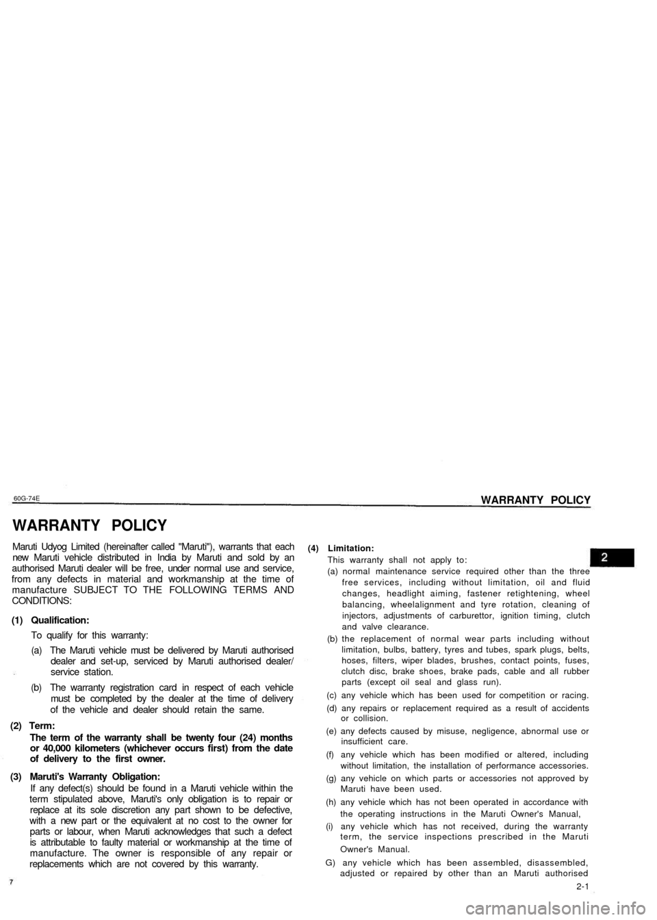
60G-00-004
The circle with a slash in this manual
means "Don't do this" or "Don't let this
happen".
Do not modify this vehicle. Modification
could adversely affect safety, handling,
performance, or durability and may
contravene regulations. In addition,
damage or performance problems
resulting from modification may not be
covered under warranty.
Improper installation of mobile
communication equipment such as
cellular talephones or CB (Citizen's
Band) radios may cause electronic
interference with your vehicle's ignition
system, resulting in vehicle
performance problems. Consult your
MARUTI dealer or qualified service
technician for advice on installing such
mobile communication equipment.
0-2
Copying, quoting or reproduction of any
part of this manual is not permitted without
explicit approval by MARUTI UDYOG
LIMITED.
60G-74E
WARRANTY POLICY
WARRANTY POLICY
Maruti Udyog Limited (hereinafter called "Maruti"), warrants that each
new Maruti vehicle distributed in India by Maruti and sold by an
authorised Maruti dealer will be free, under normal use and service,
from any defects in material and workmanship at the time of
manufacture SUBJECT TO THE FOLLOWING TERMS AND
CONDITIONS:
(1) Qualification:
To qualify for this warranty:
(a) The Maruti vehicle must be delivered by Maruti authorised
dealer and set-up, serviced by Maruti authorised dealer/
service station.
(b) The warranty registration card in respect of each vehicle
must be completed by the dealer at the time of delivery
of the vehicle and dealer should retain the same.
(2) Term:
The term of the warranty shall be twenty four (24) months
or 40,000 kilometers (whichever occurs first) from the date
of delivery to the first owner.
(3) Maruti's Warranty Obligation:
If any defect(s) should be found in a Maruti vehicle within the
term stipulated above, Maruti's only obligation is to repair or
replace at its sole discretion any part shown to be defective,
with a new part or the equivalent at no cost to the owner for
parts or labour, when Maruti acknowledges that such a defect
is attributable to faulty material or workmanship at the time of
manufacture. The owner is responsible of any repair or
replacements which are not covered by this warranty.
(4) Limitation:
This warranty shall not apply to:
(a) normal maintenance service required other than the three
free services, including without limitation, oil and fluid
changes, headlight aiming, fastener retightening, wheel
balancing, wheelalignment and tyre rotation, cleaning of
injectors, adjustments of carburettor, ignition timing, clutch
and valve clearance.
(b) the replacement of normal wear parts including without
limitation, bulbs, battery, tyres and tubes, spark plugs, belts,
hoses, filters, wiper blades, brushes, contact points, fuses,
clutch disc, brake shoes, brake pads, cable and all rubber
parts (except oil seal and glass run).
(c) any vehicle which has been used for competition or racing.
(d) any repairs or replacement required as a result of accidents
or collision.
(e) any defects caused by misuse, negligence, abnormal use or
insufficient care.
(f) any vehicle which has been modified or altered, including
without limitation, the installation of performance accessories.
(g) any vehicle on which parts or accessories not approved by
Maruti have been used.
(h) any vehicle which has not been operated in accordance with
the operating instructions in the Maruti Owner's Manual,
(i) any vehicle which has not received, during the warranty
term, the service inspections prescribed in the Maruti
Owner's Manual.
G) any vehicle which has been assembled, disassembled,
adjusted or repaired by other than an Maruti authorised
2-1
Page 10 of 65
60G-74E
BEFORE DRIVING
MIRRORS
60G-03-013
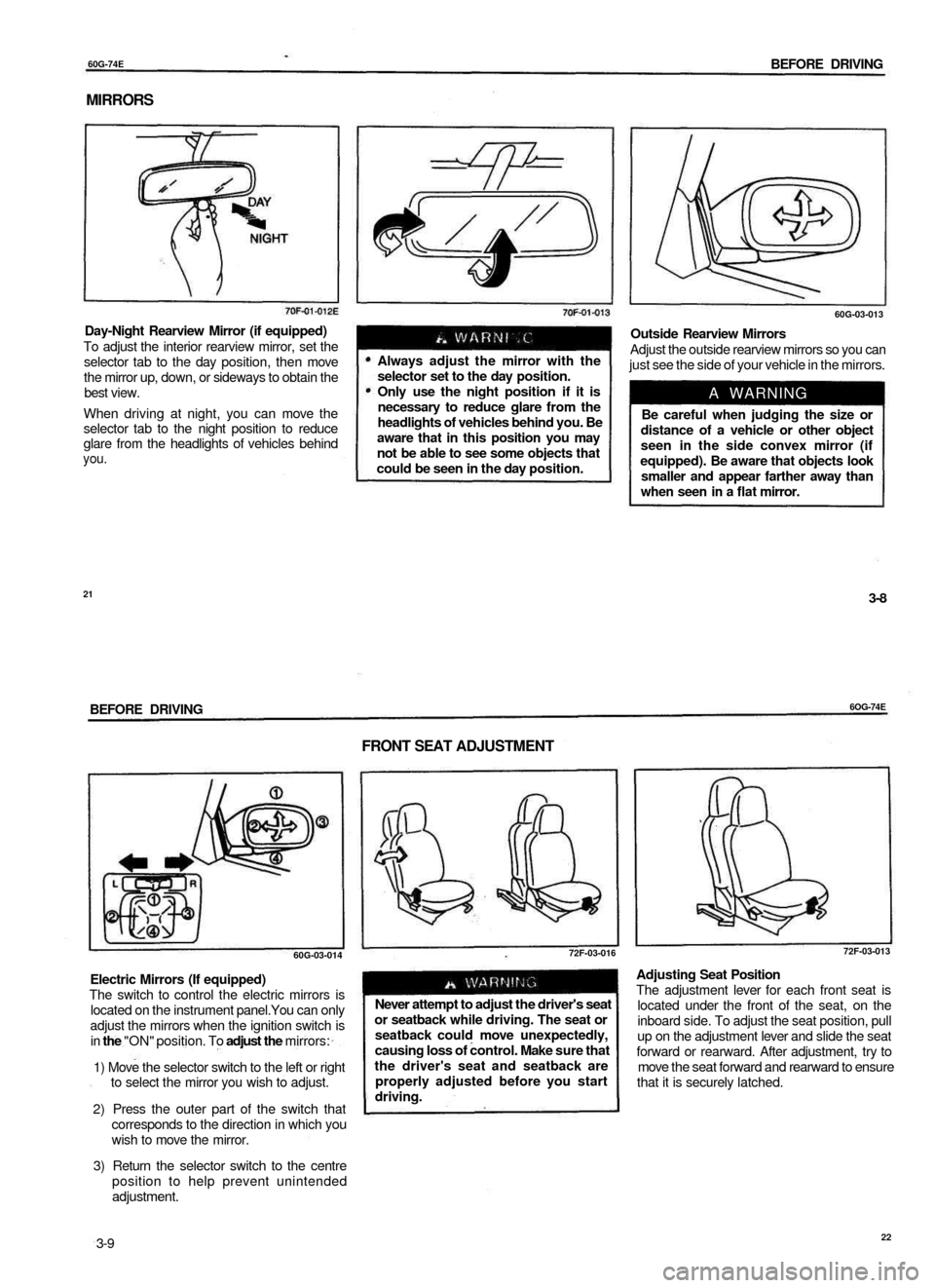
Day-Night Rearview Mirror (if equipped)
To adjust the interior rearview mirror, set the
selector tab to the day position, then move
the mirror up, down, or sideways to obtain the
best view.
When driving at night, you can move the
selector tab to the night position to reduce
glare from the headlights of vehicles behind
you.
Always adjust the mirror with the
selector set to the day position.
Only use the night position if it is
necessary to reduce glare from the
headlights of vehicles behind you. Be
aware that in this position you may
not be able to see some objects that
could be seen in the day position.
Outside Rearview Mirrors
Adjust the outside rearview mirrors so you can
just see the side of your vehicle in the mirrors.
A WARNING
Be careful when judging the size or
distance of a vehicle or other object
seen in the side convex mirror (if
equipped). Be aware that objects look
smaller and appear farther away than
when seen in a flat mirror.
21
3-8
BEFORE DRIVING
6OG-74E
FRONT SEAT ADJUSTMENT
60G-03-014
Electric Mirrors (If equipped)
The switch to control the electric mirrors is
located on the instrument panel.You can only
adjust the mirrors when the ignition switch is
in the "ON" position. To adjust the mirrors:
1) Move the selector switch to the left or right
to select the mirror you wish to adjust.
2) Press the outer part of the switch that
corresponds to the direction in which you
wish to move the mirror.
3) Return the selector switch to the centre
position to help prevent unintended
adjustment.
72F-03-016
Never attempt to adjust the driver's seat
or seatback while driving. The seat or
seatback could move unexpectedly,
causing loss of control. Make sure that
the driver's seat and seatback are
properly adjusted before you start
driving.
72F-03-013
Adjusting Seat Position
The adjustment lever for each front seat is
located under the front of the seat, on the
inboard side. To adjust the seat position, pull
up on the adjustment lever and slide the seat
forward or rearward. After adjustment, try to
move the seat forward and rearward to ensure
that it is securely latched.
3-9
22
Page 15 of 65
60G-74E
STEERING COLUMN CONTROLS
STEERING COLUMN CONTROLS
ignition Switch 4.1
Lighting/Tum Signal Control Lever 4-2
Windscreen Wiper and Washer Lever 4-4
Horn 4.5
Rear Wiper and Washer(lf equipped) 4-5
31
STEERING COLUMN CONTROLS
60G-74E
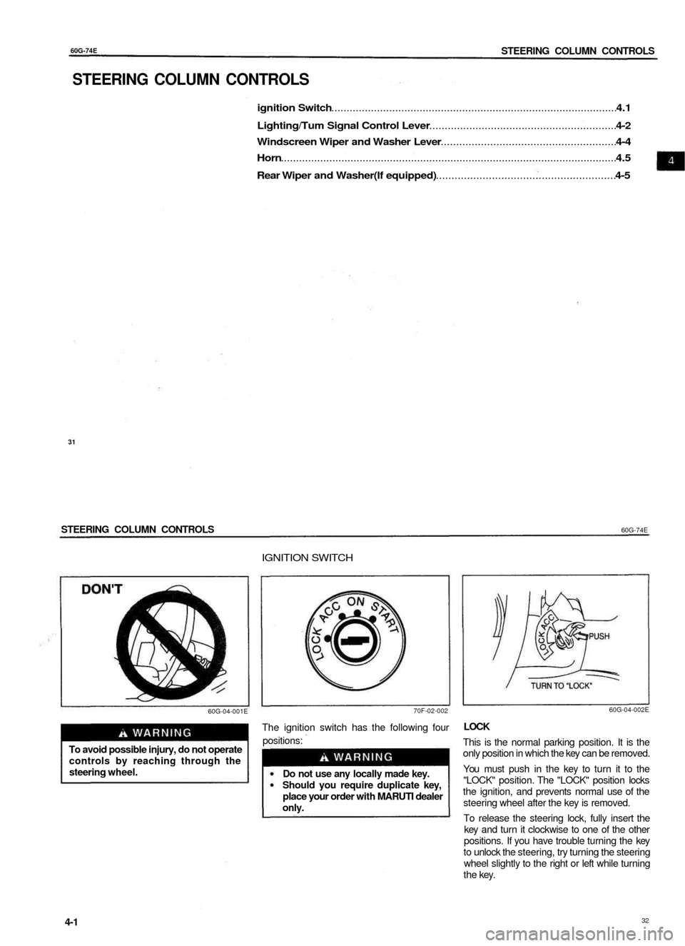
IGNITION SWITCH
60G-04-001E
70F-02-002
To avoid possible injury, do not operate
controls by reaching through the
steering wheel.
The ignition switch has the following four
positions:
Do not use any locally made key.
Should you require duplicate key,
place your order with MARUTI dealer
only.
60G-04-002E
LOCK
This is the normal parking position. It is the
only position in which the key can be removed.
You must push in the key to turn it to the
"LOCK" position. The "LOCK" position locks
the ignition, and prevents normal use of the
steering wheel after the key is removed.
To release the steering lock, fully insert the
key and turn it clockwise to one of the other
positions. If you have trouble turning the key
to unlock the steering, try turning the steering
wheel slightly to the right or left while turning
the key.
4-1
32
Page 16 of 65
6OG-74E
STEERING COLUMN CONTROLS
ACC
Accessories such as the radio can operate,
but the engine is off.
ON
This is the normal operating position. All
electrical systems are on.
START
This is the position for starting the engine using
the starter motor. The key should be released
from this position as soon as the engine starts.
Never remove the ignition key while
the vehicle is moving. The steering
wheel will lock and you will not be
able to steer the vehicle.
Do not leave children alone In a
parked vehicle. Unattended children
could cause accidental movement of
the vehicle, which could result in
severe personal Injury.
Always remove the key when parked
to prevent unintentional operation of
the vehicle and to improve security.
LIGHTING/TURN SIGNAL
CONTROL LEVER
CAUTION
Do not use the starter motor for
more than 15 seconds at a time. If
the engine does not start; wait 15
seconds before trying again. If the
engine does not start after several
attempts, check the fuel and ignition
systems or consult your MARUTI
dealer.
Do not leave the ignition switch in
the "ON" position if the engine is not
running as the battery will
discharge.
60G-04-003
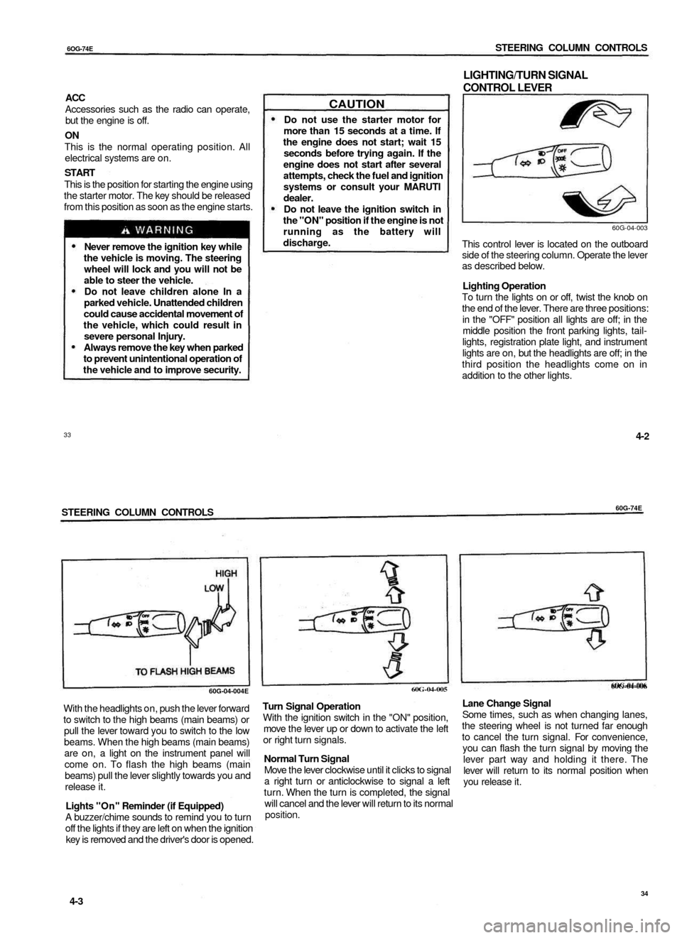
This control lever is located on the outboard
side of the steering column. Operate the lever
as described below.
Lighting Operation
To turn the lights on or off, twist the knob on
the end of the lever. There are three positions:
in the "OFF" position all lights are off; in the
middle position the front parking lights, tail-
lights, registration plate light, and instrument
lights are on, but the headlights are off; in the
third position the headlights come on in
addition to the other lights.
33
4-2
STEERING COLUMN CONTROLS
60G-74E
With the headlights on, push the lever forward
to switch to the high beams (main beams) or
pull the lever toward you to switch to the low
beams. When the high beams (main beams)
are on, a light on the instrument panel will
come on. To flash the high beams (main
beams) pull the lever slightly towards you and
release it.
Lights "On" Reminder (if Equipped)
A buzzer/chime sounds to remind you to turn
off the lights if they are left on when the ignition
key is removed and the driver's door is opened.
Turn Signal Operation
With the ignition switch in the "ON" position,
move the lever up or down to activate the left
or right turn signals.
Normal Turn Signal
Move the lever clockwise until it clicks to signal
a right turn or anticlockwise to signal a left
turn. When the turn is completed, the signal
will cancel and the lever will return to its normal
position.
6OG-04-006
Lane Change Signal
Some times, such as when changing lanes,
the steering wheel is not turned far enough
to cancel the turn signal. For convenience,
you can flash the turn signal by moving the
lever part way and holding it there. The
lever will return to its normal position when
you release it.
4-3
34
60G-04-006
60G-04-005
60G-04-004E
Page 17 of 65
60G-74E
STEERING COLUMN CONTROLS
WINDSCREEN WIPER AND
WASHER LEVER
60G-04-007E
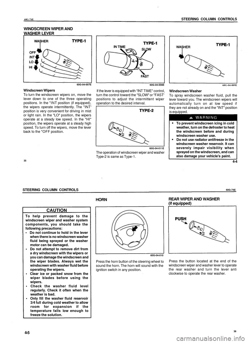
Windscreen Wipers
To turn the windscreen wipers on, move the
lever down to one of the three operating
positions. In the "INT position (if equipped),
the wipers operate intermittently. The "INT'
position is very convenient for driving in mist
or light rain. In the "LO" position, the wipers
operate at a steady low speed. In the "HI"
position, the wipers operate at a steady high
speed. To turn off the wipers, move the lever
back to the "OFF position.
60G-04-008E
If the lever is equipped with "INT TIME" control,
turn the control toward the "SLOW" or "FAST'
positions to adjust the intermittent wiper
operation to the desired interval.
60G-04-011E
The operation of windscreen wiper and washer
Type-2 is same as Type-1.
60G-04-009E
Windscreen Washer
To spray windscreen washer fluid, pull the
lever toward you. The windscreen wipers will
automatically turn on at low speed if
they are not already on and the "INT" position
is equipped.
To prevent windscreen icing in cold
weather, turn on the defroster to heat
the windscreen before and during
windscreen washer use.
Do not use radiator antifreeze in the
windscreen washer reservoir. It can
severely impair visibility when
sprayed on the windscreen, and can
also damage your vehicle's paint.
35
4-4
STEERING COLUMN CONTROLS
60G-74E
CAUTION
To help prevent damage to the
windscreen wiper and washer system
components, you should take the
following precautions:
• Do not continue to hold in the lever
when there is no windscreen washer
fluid being sprayed or the washer
motor can be damaged.
• Do not attempt to remove dirt from
a dry windscreen with the wipers or
you can damage the windscreen and
the wiper blades. Always wet the
windscreen with washer fluid before
operating the wipers.
• Clear ice or packed snow from the
wiper blades before using the
wipers.
• Check the washer fluid level
regularly. Check it often when the
weather is bad.
• Only fill the washer fluid reservoir
3/4 full during cold weather to allow
room for expansion if the
temperature falls low enough to
freeze the solution.
HORN
REAR WIPER AND WASHER
(if equipped)
60G-04-010
Press the horn button of the steering wheel to
sound the horn. The horn will sound with the
ignition switch in any position.
Press the button located at the end of the
windscreen wiper and washer lever to operate
the rear washer and turn the lever anti
clockwise to operate the rear washer.
4-5
36
Page 18 of 65
60G-74E
INSTRUMENT PANEL
INSTRUMENT PANEL
Instrument Panel 5-1
Instrument Cluster 5-2
Warning and Indicator Lights 5-3
Speedometer/Odometer/Tripmeter (if equipped) 5-5
Tachometer (if equipped) 5-6
Fuel Gauge 5-6
Temperature Gauge 5-6
Hazard Warning Switch 5-7
Rear Window Defroster Switch (if equipped) 5-7
Cigarette Lighter (if equipped) 5-7
Ashtray 5-8
Glove Box 5-8
Heating System (if equipped) 5-9
System Operating Instructions 5-10
Air Conditioning System (if equipped) 5-13
System Operating Instructions 5-13
37
INSTRUMENT PANEL
60G-74E
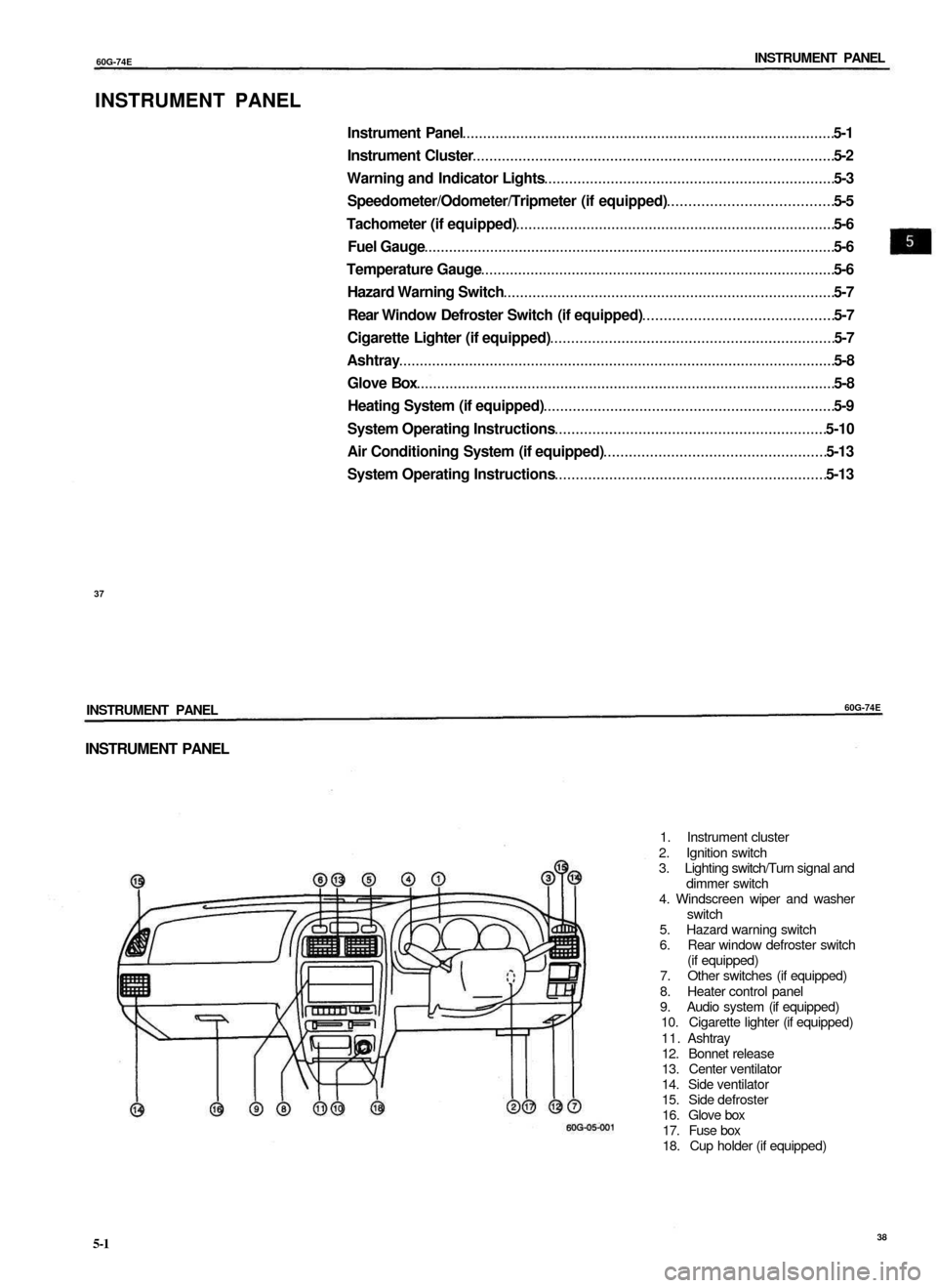
INSTRUMENT PANEL
1. Instrument cluster
2. Ignition switch
3. Lighting switch/Turn signal and
dimmer switch
4. Windscreen wiper and washer
switch
5. Hazard warning switch
6. Rear window defroster switch
(if equipped)
7. Other switches (if equipped)
8. Heater control panel
9. Audio system (if equipped)
10. Cigarette lighter (if equipped)
11. Ashtray
12. Bonnet release
13. Center ventilator
14. Side ventilator
15. Side defroster
16. Glove box
17. Fuse box
18. Cup holder (if equipped)
5-1
38
Page 19 of 65

60G-74E
INSTRUMENT PANEL
INSTRUMENT CLUSTER
© Speedometer
® Odometer
© Trip meter (if equipped)
© Trip meter reset knob
© Tachometer (if equipped)
© Fuel gauge
® Temperature gauge
© Warning and indicator lights
60G-05-002
39
5-2
INSTRUMENT PANEL
60G-74E
WARNING AND INDICATOR LIGHTS
70F-07-070
Brake fluid level warning/Parking Brake
Indicator light
This light operates under three conditions:
1) when the ignition switch is turned to the
"START' position, 2) when the fluid in the brake
fluid reservoir falls below the specified level
or 3) when the parking brake is not fully
released and the ignition switch is in the "ON"
position. The light should go out after starting
the engine and fully releasing the parking
brake, if the fluid in the brake fluid reservoir is
adequate. If the light does not go off or comes
on whilst you are driving, it may mean that
there is something wrong with the vehicle's
braking system. If this happens, you should:
1) Pull off the road and stop carefully.
Remember that stopping distance may
be longer, you may have to push
harder on the pedal, and the pedal
may go down farther than normal.
2) Test the brakes by carefully starting and
stopping at the side of the road.
3) If you determine that it is safe, drive
carefully at low speed to the nearest dealer
for repairs.
Have the vehicle towed to the nearest
dealer for repairs.
or
4)
If any of the following conditions occur,
you should Immediately ask your
MARUTI dealer to inspect the brake
system.
• If the brake fluid level warning light
does not go out after the engine has
been started and the parking brake
has been fully released.
• If the brake fluid level warning light
does not come on when the ignition
switch is turned to the "START"
position.
• If the brake fluid level warning light
comes on at any time during vehicle
operation.
NOTE:
Because the disc brake system is self
adjusting, the fluid level will drop as the brake
pads become worn.
Replenishing the brake fluid reservoir is
considered normal periodic maintenance.
70F-03-039
Oil Pressure Light
This light comes on when the ignition switch
is turned on, and goes out when the engine
is started. The light will come on and remain
on if there is insufficient oil pressure. If the
light comes on when driving, pull off the
road as soon as you can and stop the
engine. Check the oil level and add oil if
necessary (see pages 9-8 and 9-9). If there
is enough oil, the lubrication system should
be inspected by your MARUTI dealer before
you drive the vehicle again.
5-3
40
Page 20 of 65
60G-74E
INSTRUMENT PANEL
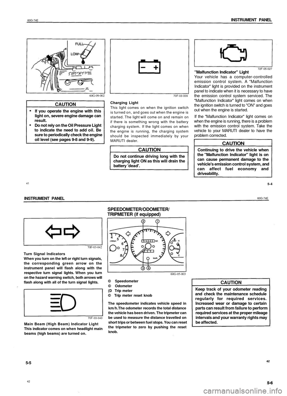
60G-09-002
CAUTION
If you operate the engine with this
light on, severe engine damage can
result.
Do not rely on the Oil Pressure Light
to indicate the need to add oil. Be
sure to periodically check the engine
oil level (see pages 9-8 and 9-9).
70F-03-009
Charging Light
This light comes on when the ignition switch
is turned on, and goes out when the engine is
started. The light will come on and remain on
if there is something wrong with the battery
charging system. If the light comes on when
the engine is running, the charging system
should be inspected immediately by your
MARUTI dealer.
CAUTION
Do not continue driving long with the
charging light ON as this will drain the
battery 'dead'.
72F-05-027
"Malfunction Indicator" Light
Your vehicle has a computer-controlled
emission control system. A "Malfunction
Indicator" light is provided on the instrument
panel to indicate when it is necessary to have
the emission control system serviced. The
"Malfunction Indicator" light comes on when
the ignition switch is turned to "ON" and goes
out when the engine is started.
If the "Malfunction Indicator" light comes on
when the engine is running, there is a problem
with the emission control system. Take the
vehicle to your MARUTI dealer to have the
problem corrected.
CAUTION
Continuing to drive the vehicle when
the "Malfunction Indicator" light is on
can cause permanent damage to the
vehicle's emission control system, and
can affect fuel economy and
driveability.
5-4
INSTRUMENT PANEL
60G-74E
70F-03-042
Turn Signal Indicators
When you turn on the left or right turn signals,
the corresponding green arrow on the
instrument panel will flash along with the
respective turn signal lights. When you turn
on the hazard warning switch, both arrows will
flash along with all of the turn signal lights.
70F-03-043
Main Beam (High Beam) Indicator Light
This indicator comes on when headlight main
beams (high beams) are turned on.
SPEEDOMETER/ODOMETER/
TRIPMETER (if equipped)
60G-05-003
© Speedometer
© Odometer
(D Trip meter
© Trip meter reset knob
The speedometer indicates vehicle speed in
km/h.The odometer records the total distance
the vehicle has been driven. The tripmeter can
be used to measure the distance travelled on
short trips or between fuel stops. You can reset
the tripmeter to zero by pushing the reset
knob.
CAUTION
Keep track of your odometer reading
and check the maintenance schedule
regularly for required services.
Increased wear or damage to certain
parts can result from failure to perform
required services at the proper mileage
intervals and your warranty rights may
be affected.
5-5
42
41
Page 21 of 65
60G-74E
INSTRUMENT PANEL
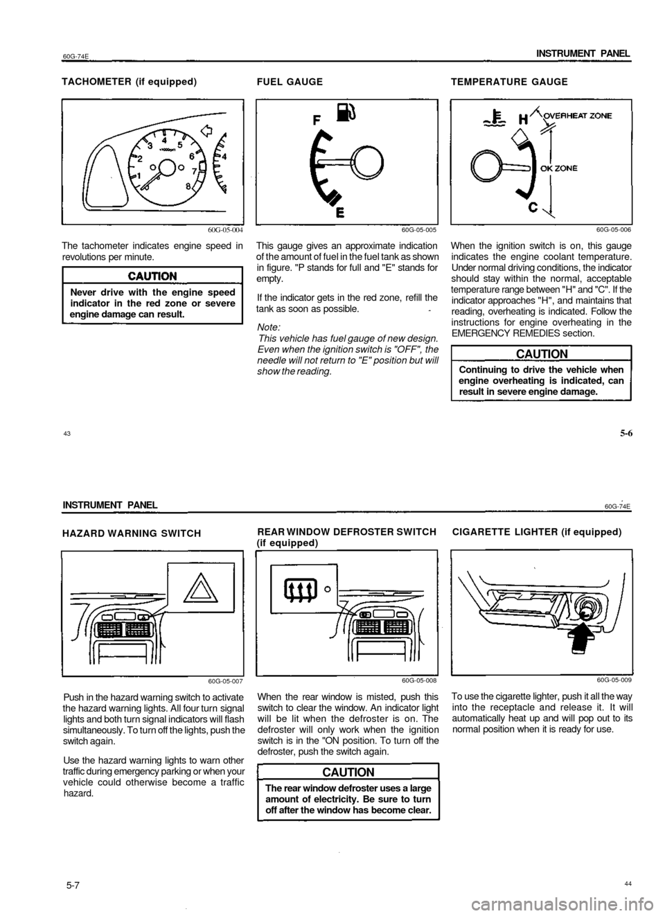
TACHOMETER (if equipped)
FUEL GAUGE
TEMPERATURE GAUGE
60G-05-004
The tachometer indicates engine speed in
revolutions per minute.
Never drive with the engine speed
indicator in the red zone or severe
engine damage can result.
60G-05-005
This gauge gives an approximate indication
of the amount of fuel in the fuel tank as shown
in figure. "P stands for full and "E" stands for
empty.
If the indicator gets in the red zone, refill the
tank as soon as possible.
Note:
This vehicle has fuel gauge of new design.
Even when the ignition switch is "OFF", the
needle will not return to "E" position but will
show the reading.
60G-05-006
When the ignition switch is on, this gauge
indicates the engine coolant temperature.
Under normal driving conditions, the indicator
should stay within the normal, acceptable
temperature range between "H" and "C". If the
indicator approaches "H", and maintains that
reading, overheating is indicated. Follow the
instructions for engine overheating in the
EMERGENCY REMEDIES section.
CAUTION
Continuing to drive the vehicle when
engine overheating is indicated, can
result in severe engine damage.
43
5-6
INSTRUMENT PANEL
60G-74E
HAZARD WARNING SWITCH
REAR WINDOW DEFROSTER SWITCH CIGARETTE LIGHTER (if equipped)
(if equipped)
60G-05-007
Push in the hazard warning switch to activate
the hazard warning lights. All four turn signal
lights and both turn signal indicators will flash
simultaneously. To turn off the lights, push the
switch again.
Use the hazard warning lights to warn other
traffic during emergency parking or when your
vehicle could otherwise become a traffic
hazard.
60G-05-008
When the rear window is misted, push this
switch to clear the window. An indicator light
will be lit when the defroster is on. The
defroster will only work when the ignition
switch is in the "ON position. To turn off the
defroster, push the switch again.
CAUTION
The rear window defroster uses a large
amount of electricity. Be sure to turn
off after the window has become clear.
60G-05-009
To use the cigarette lighter, push it all the way
into the receptacle and release it. It will
automatically heat up and will pop out to its
normal position when it is ready for use.
5-7
44