engine SUZUKI CELERIO 2022 Workshop Manual
[x] Cancel search | Manufacturer: SUZUKI, Model Year: 2022, Model line: CELERIO, Model: SUZUKI CELERIO 2022Pages: 201, PDF Size: 5.82 MB
Page 158 of 201
7-9
INSPECTION AND MAINTENANCE
76MH1-74E
76MH1-74E
4) Reinstall the drain plug and gasket. Tighten the plug with a wrench to thespecified torque.
Replace the Oil Filter
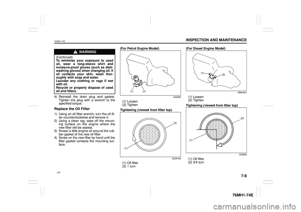
1) Using an oil filter wrench, turn the oil fil-ter counterclockwise and remove it. 2) Using a clean rag, wipe off the mount- ing surface on the engine where thenew filter will be seated. 3) Smear a little engine oil around the rub- ber gasket of the new oil filter.4) Screw on the new filter by hand until the filter gasket contacts the mounting sur- face.
(For Petrol Engine Model)
54G092
(1) Loosen (2) Tighten
Tightening (viewed from filter top)
82JN146
(1) Oil filter (2) 1 turn
(For Diesel Engine Model)
76MH031
(1) Loosen (2) Tighten
Tightening (viewed from filter top)
54G093
(1) Oil filter (2) 3/4 turn
WA R N I N G
(Continued) To minimize your exposure to usedoil, wear a long-sleeve shirt and moisture-proof gloves (such as dish- washing gloves) when changing oil. Ifoil contacts your skin, wash thor- oughly with soap and water. Launder any clothing or rags if wetwith oil. Recycle or properly dispose of used oil and filters.
(1)
(2)
(1) (2)
147
Page 159 of 201
7-10
INSPECTION AND MAINTENANCE
76MH1-74E
76MH1-74E
5) Tighten the filter specified turn from the point of contact with the mounting sur- face (or to the spec ified torque) using an oil filter wrench.
Tightening torque for oil filter Petrol engine: 1 turn or 14 Nm (1.4 kg-m, 10.3 lb-ft)Diesel engine: 3/4 turn or 14 Nm (1.4 kg-m, 10.3 lb-ft)
Refill with Oil and Check for Leaks1) Pour oil through the filler hole andinstall the filler cap. For the approximate capacity of the oil, refer to the “CAPACITIES” item in the “SPECIFICATIONS” section.2) Start the engine and look carefully for leaks at the oil filter and drain plug. Run the engine at various speeds for at least5 minutes.
3) Stop the engine and wait about 5 min- utes. Check the oil level again and add oil if necessary. Check for leaks again.
Engine Coolant
Selection of CoolantTo maintain optimum performance anddurability of your engine, use MARUTIGenuine Coolant or equivalent. This type of coolant is best for your cooling system as it: Helps maintain proper engine tempera- ture. Gives proper protection against freezingand boiling. Gives proper protection against corro- sion and rust.Failure to use the proper coolant can dam- age your cooling system. Your authorized
MARUTI SUZUKI dealer can help you select the proper coolant.
Coolant Level CheckCheck the coolant level at the reservoirtank, not at the radiator. With the engine cool, the coolant level should be betweenthe “FULL” and “LOW” marks.
NOTICE
To tighten the oil filter properly, it isImportant to accurately identify theposition at which the filter gasket first contacts the mounting surface.
NOTICE
To prevent oil leakage, make sure that the oil filter is tight, but do notover-tighten it.
NOTICE
• When replacing the oil filter, it is rec-ommended that you use a Marutigenuine replacement filter. If you use an after market filter, make sure it is of equivalent quality and followthe manufacturer’s instructions. • Oil leaks from around the oil filter or drain plug indicate incorrectinstallation or gasket damage. If you find any leaks or are not sure that the filter has been properlytightened, have the vehicle inspected by your MARUTI SUZUKI dealer.
NOTICE
To avoid damaging your cooling sys- tem: • Always use a high quality ethyleneglycol base non-silicate type cool- ant diluted with distilled water at the correct mixture concentration.• Make sure that the proper mix is 50/ 50 coolant to distilled water (Die- sel) and 30/70 (Petrol). Concentra-tions greater than this may cause overheating conditions. • Neither use 100% coolant nor 100%Plain water. • Do not add extra inhibitors or addi- tives. They may not be compatiblewith your cooling system. • Do not mix different types of base coolants. Doing so may result inaccelerated seal wear and/or the possibility of severe overheating and extensive engine damage.
148
Page 160 of 201
7-11
INSPECTION AND MAINTENANCE
76MH1-74E
76MH1-74E
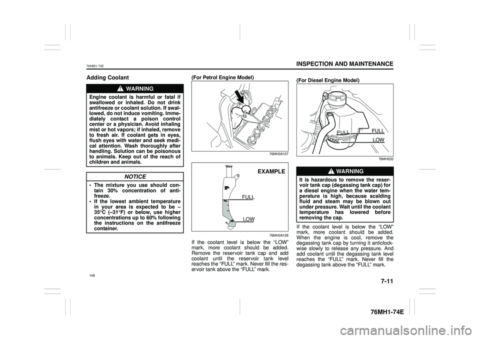
Adding Coolant(For Petrol Engine Model)
76MH0A107
76MH0A108
If the coolant level is below the “LOW” mark, more coolant should be added. Remove the reservoir tank cap and add coolant until the reservoir tank level reaches the “FULL” mark. Never fill the res- ervoir tank above the “FULL” mark.
(For Diesel Engine Model)
76MH032
If the coolant level is below the “LOW” mark, more coolant should be added. When the engine is cool, remove the degassing tank cap by turning it anticlock-wise slowly to release any pressure. And add coolant until the degassing tank level reaches the “FULL” mark. Never fill thedegassing tank above the “FULL” mark.
WA R N I N G
Engine coolant is harmful or fatal if swallowed or inhaled. Do not drink antifreeze or coolant solution. If swal-lowed, do not induce vomiting. Imme- diately contact a poison control center or a physician. Avoid inhalingmist or hot vapors; if inhaled, remove to fresh air. If coolant gets in eyes, flush eyes with water and seek medi-cal attention. Wash thoroughly after handling. Solution can be poisonous to animals. Keep out of the reach ofchildren and animals.
NOTICE
• The mixture you use should con- tain 30% concentration of anti- freeze.• If the lowest am bient temperature in your area is expected to be – 35°C (–31°F) or below, use higherconcentrations up to 60% following the instructions on the antifreeze container.
EXAMPLE
FULL
LOW
WA R N I N G
It is hazardous to remove the reser- voir tank cap (degassing tank cap) for a diesel engine when the water tem- perature is high, because scaldingfluid and steam may be blown out under pressure. Wait until the coolant temperature has lowered beforeremoving the cap.
FULL
LOW
149
Page 161 of 201
7-12
INSPECTION AND MAINTENANCE
76MH1-74E
76MH1-74E
Coolant ReplacementSince special procedures are required, we recommend you take your vehicle to your MARUTI SUZUKI dealer for coolant replacement.
Air Cleaner
If the air cleaner is clogged with dust, therewill be greater intake resistance, resulting in decreased power output and increased fuel consumption.
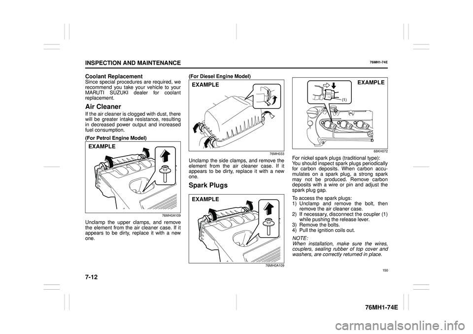
(For Petrol Engine Model)
76MH0A109
Unclamp the upper clamps, and remove the element from the air cleaner case. If itappears to be dirty, replace it with a new one.
(For Diesel Engine Model)
76MH033
Unclamp the side clamps, and remove the element from the air cleaner case. If it appears to be dirty, replace it with a newone.
Spark Plugs
76MH0A109
68KH072
For nickel spark plugs (traditional type): You should inspect spark plugs periodically for carbon deposits. When carbon accu-mulates on a spark plug, a strong spark may not be produced. Remove carbon deposits with a wire or pin and adjust thespark plug gap.
To access the spark plugs: 1) Unclamp and remove the bolt, then remove the air cleaner case. 2) If necessary, disconnect the coupler (1)while pushing the release lever. 3) Remove the bolts. 4) Pull the ignition coils out.
NOTE: When installation, make sure the wires,couplers, sealing rubber of top cover and washers, are correctly returned in place.
EXAMPLE
EXAMPLE
EXAMPLE
(1)
EXAMPLE
150
Page 162 of 201

7-13
INSPECTION AND MAINTENANCE
76MH1-74E
76MH1-74E
78K179 60G160S 60B307
Spark plug gap “a” NGK KR6A-10: 0.95 – 1.05 mm (0.037 – 0.041 in.)NOTICE
• When pulling the ignition coils out,do not pull on the cable. Pulling onthe cable can damage it. • When servicing the iridium/plati- num spark plugs (slender centerelectrode type plugs), do not touch the center electrode, as it is easy to damage.
Correct Wrong
EXAMPLE
NOTICE
• When installing the spark plugs,screw them in with your fingers to avoid stripping the threads. Tighten with a torque wrench to 17.5 Nm (1.8 kg-m, 12.9 lb-ft). Donot allow contaminants to enter the engine through the spark plug holes when the plugs are removed.• Never use spark plugs with the wrong thread size.
Loosen
Tighten
NOTICE
When replacing spark plugs, you should use the brand and type speci-fied for your vehicle. For the speci- fied plugs, refer to the “SPECIFICATIONS” section at theend of this book. If you wish to use a brand of spark plug other than the specified plugs, consult your MAR-UTI SUZUKI dealer.
151
Page 163 of 201
7-14
INSPECTION AND MAINTENANCE
76MH1-74E
76MH1-74E
Gear Oil
Manual Transaxle Oil/
Auto Gear Shift OilWhen adding gear oil, use gear oil with the appropriate viscosity and grade as shown in the chart below.
We highly recommend you use: “MARUTI SUZUKI GEAR OIL 75W-80” formanual transaxle gear oil or Auto Gear Shift oil.
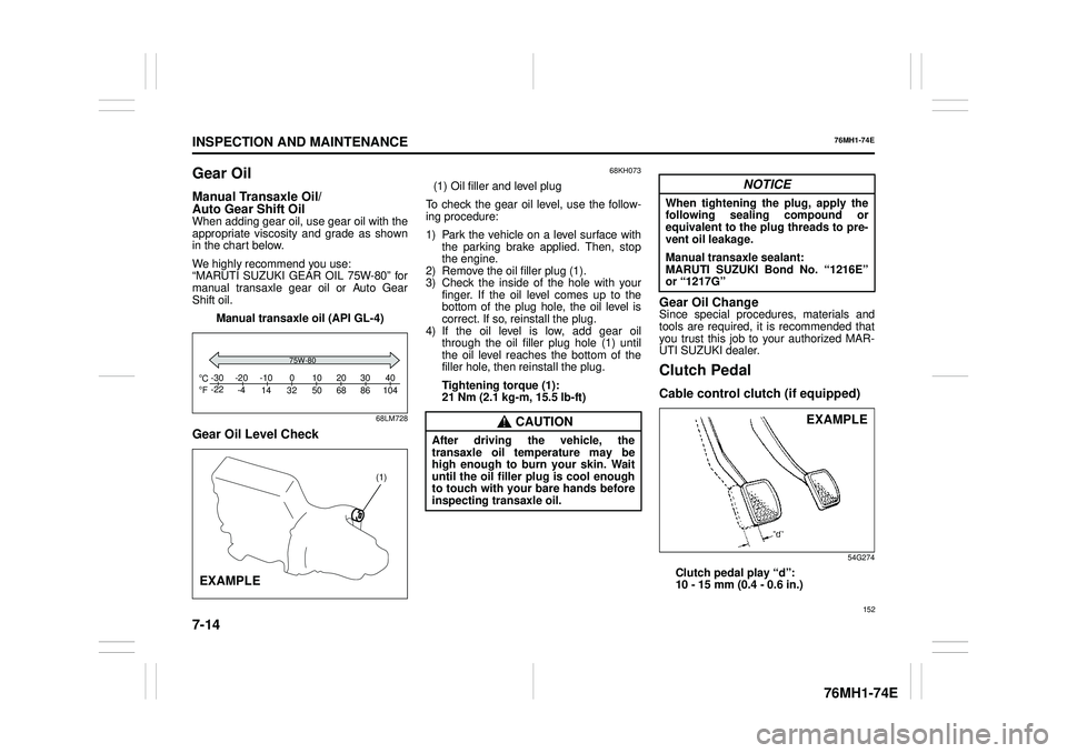
Manual transaxle oil (API GL-4)
68LM728
Gear Oil Level Check
68KH073
(1) Oil filler and level plug
To check the gear oil level, use the follow- ing procedure:
1) Park the vehicle on a level surface with the parking brake applied. Then, stop the engine.2) Remove the oil filler plug (1). 3) Check the inside of the hole with your finger. If the oil level comes up to thebottom of the plug hole, the oil level is correct. If so, reinstall the plug. 4) If the oil level is low, add gear oilthrough the oil filler plug hole (1) until the oil level reaches the bottom of the filler hole, then reinstall the plug.
Tightening torque (1): 21 Nm (2.1 kg -m, 15.5 lb-ft)
Gear Oil ChangeSince special procedures, materials and tools are required, it is recommended that you trust this job to your authorized MAR-UTI SUZUKI dealer.
Clutch Pedal
Cable control clutch (if equipped)
54G274
Clutch pedal play “d”: 10 - 15 mm (0.4 - 0.6 in.)
C Fo o-30 -22 -20 -4 -10 14 32 50 68 86 104 010203040
75W-80
(1)
EXAMPLE
CAUTION
After driving the vehicle, the transaxle oil temperature may behigh enough to burn your skin. Wait until the oil filler plug is cool enough to touch with your bare hands beforeinspecting transaxle oil.
NOTICE
When tightening the plug, apply thefollowing sealing compound orequivalent to the plug threads to pre- vent oil leakage.
Manual transaxle sealant: MARUTI SUZUKI Bond No. “1216E” or “1217G”
EXAMPLE
152
Page 164 of 201
7-15
INSPECTION AND MAINTENANCE
76MH1-74E
76MH1-74E
Measure the clutch pedal play by moving the clutch pedal with your hand and mea- suring the distance it moves until you feelslight resistance. The play in the clutch pedal should be between the specified val- ues. If the play is more or less than theabove, or clutch dragging is felt with the pedal fully depressed, have the clutch inspected by your MARUTI SUZUKIdealer.
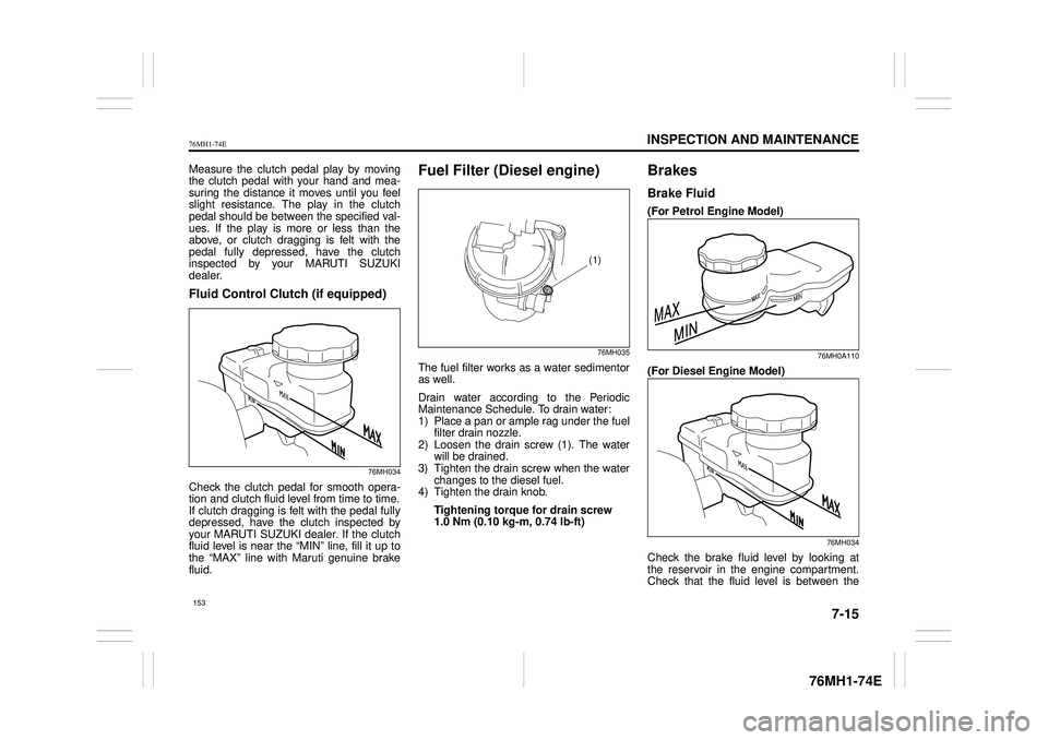
Fluid Control Clutch (if equipped)
76MH034
Check the clutch pedal for smooth opera-tion and clutch fluid level from time to time.If clutch dragging is felt with the pedal fully depressed, have the clutch inspected by your MARUTI SUZUKI dealer. If the clutchfluid level is near the “MIN” line, fill it up to the “MAX” line with Maruti genuine brake fluid.
Fuel Filter (Diesel engine)
76MH035
The fuel filter works as a water sedimentoras well.
Drain water according to the Periodic Maintenance Schedule. To drain water:1) Place a pan or ample rag under the fuel filter drain nozzle. 2) Loosen the drain screw (1). The waterwill be drained. 3) Tighten the drain screw when the water changes to the diesel fuel.4) Tighten the drain knob.
Tightening torque for drain screw 1.0 Nm (0.10 kg-m, 0.74 lb-ft)
Brakes
Brake Fluid
(For Petrol Engine Model)
76MH0A110
(For Diesel Engine Model)
76MH034
Check the brake fluid level by looking atthe reservoir in the engine compartment.Check that the fluid level is between the
(1)
153
Page 165 of 201
7-16
INSPECTION AND MAINTENANCE
76MH1-74E
76MH1-74E
“MAX” and “MIN” lines. If the brake fluid level is near the “MIN” line, fill it up to the “MAX” line with Maruti genuine brake fluid.
NOTE: With disc brakes, the fluid level can beexpected to gradually fall as the brake pads wear.
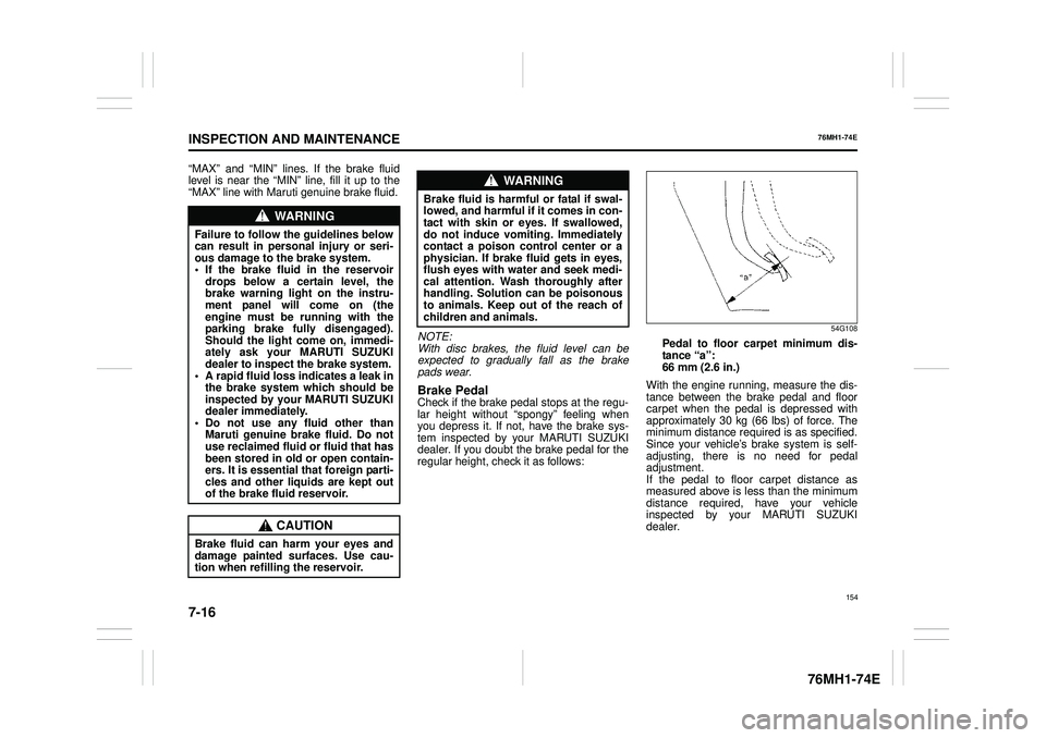
Brake PedalCheck if the brake peda l stops at the regu- lar height without “spongy” feeling when you depress it. If not, have the brake sys- tem inspected by your MARUTI SUZUKIdealer. If you doubt the brake pedal for the regular height, check it as follows:
54G108
Pedal to floor car pet minimum dis- tance “a”: 66 mm (2.6 in.)
With the engine running, measure the dis- tance between the brake pedal and floorcarpet when the pedal is depressed with approximately 30 kg (66 lbs) of force. The minimum distance required is as specified.Since your vehicle’s brake system is self- adjusting, there is no need for pedal adjustment. If the pedal to floor carpet distance as measured above is less than the minimum distance required, have your vehicleinspected by your MARUTI SUZUKI dealer.
WA R N I N G
Failure to follow the guidelines below can result in personal injury or seri-ous damage to the brake system. • If the brake fluid in the reservoir drops below a certain level, thebrake warning light on the instru- ment panel will come on (the engine must be running with theparking brake fully disengaged). Should the light come on, immedi- ately ask your MARUTI SUZUKIdealer to inspect the brake system. • A rapid fluid loss indicates a leak in the brake system which should beinspected by your MARUTI SUZUKI dealer immediately. • Do not use any fluid other thanMaruti genuine brake fluid. Do not use reclaimed fluid or fluid that has been stored in old or open contain-ers. It is essential that foreign parti- cles and other liquids are kept out of the brake fluid reservoir.
CAUTION
Brake fluid can harm your eyes anddamage painted surfaces. Use cau- tion when refilling the reservoir.
WA R N I N G
Brake fluid is harmful or fatal if swal- lowed, and harmful if it comes in con-tact with skin or e yes. If swallowed, do not induce vomiting. Immediately contact a poison control center or aphysician. If brake fluid gets in eyes, flush eyes with water and seek medi- cal attention. Wash thoroughly afterhandling. Solution can be poisonous to animals. Keep out of the reach of children and animals.
154
Page 169 of 201
7-20
INSPECTION AND MAINTENANCE
76MH1-74E
76MH1-74E
76MH0A136
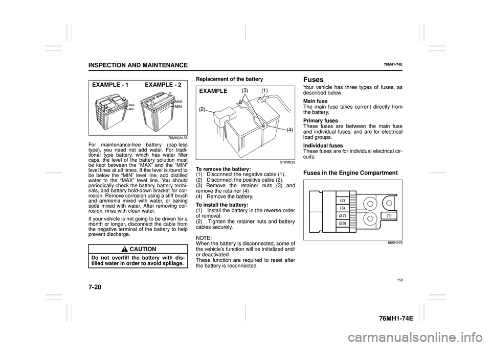
For maintenance-free battery (cap-less type), you need not add water. For tradi-tional type battery, which has water filler caps, the level of the battery solution must be kept between the “MAX” and the “MIN”level lines at all times. If the level is found tobe below the “MIN” level line, add distilledwater to the “MAX” level line. You shouldperiodically check the battery, battery termi- nals, and battery hold-down bracket for cor- rosion. Remove corrosion using a stiff brushand ammonia mixed with water, or bakingsoda mixed with water. After removing cor-rosion, rinse with clean water.
If your vehicle is not going to be driven for amonth or longer, disconnect the cable fromthe negative terminal of the battery to help prevent discharge.
Replacement of the battery
51KM039
To remove the battery: (1) Disconnect the negative cable (1). (2) Disconnect the positive cable (2). (3) Remove the retainer nuts (3) andremove the retainer (4) (4) Remove the battery.
To install the battery: (1) Install the battery in the reverse order of removal. (2) Tighten the retainer nuts and battery cables securely.
NOTE: When the battery is disconnected, some of the vehicle’s function will be initialized and/or deactivated. These function are required to reset after the battery is reconnected.
Fuses
Your vehicle has three types of fuses, asdescribed below:
Main fuse The main fuse takes current directly fromthe battery.
Primary fuses These fuses are between the main fuse and individual fuses, and are for electrical load groups.
Individual fuses These fuses are for individual electrical cir-cuits.
Fuses in the Engine Compartment
68KH076
CAUTION
Do not overfill th e battery with dis- tilled water in order to avoid spillage.
EXAMPLE - 1 EXAMPLE - 2(1)
(2)
(3)
(4)
EXAMPLE
(1)
(2)
(3)
(27)
(28)
158
Page 170 of 201
7-21
INSPECTION AND MAINTENANCE
76MH1-74E
76MH1-74E
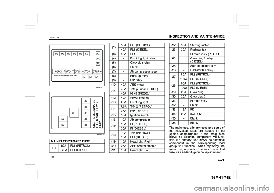
68KH077
76MH036
The main fuse, primary fuses and some of the individual fuses are located in the engine compartment. If the main fuse blows, no electrical component will func-tion. If a primary fuse blows, no electrical component in the corresponding load group will function. When replacing themain fuse, a primary fuse or an individual fuse, use a Maruti genuine replacement.
MAIN FUSE/PRIMARY FUSE
(1) 80A FL1 (PETROL)
120A FL1 (DIESEL)
(4)
(24) (25) (26)
(13) (14) (15) (16) (17) (18) (19) (20) (21) (22) (23)
(10)
(11)
(12)
(5) (6) (7) (8) (9)
(29)
(30)
(31)
(32)
(33)
(34)
(35)
(36)
(2) 50A FL5 (PETROL)
40A FL5 (DIESEL)
(3) 50A FL4
(4) – Front fog light relay
(5)