service SUZUKI ERTIGA 2013 1.G User Guide
[x] Cancel search | Manufacturer: SUZUKI, Model Year: 2013, Model line: ERTIGA, Model: SUZUKI ERTIGA 2013 1.GPages: 207, PDF Size: 5.14 MB
Page 142 of 207
Downloaded from www.Manualslib.com manuals search engine 5-47OTHER CONTROLS AND EQUIPMENT
60MK0-14E
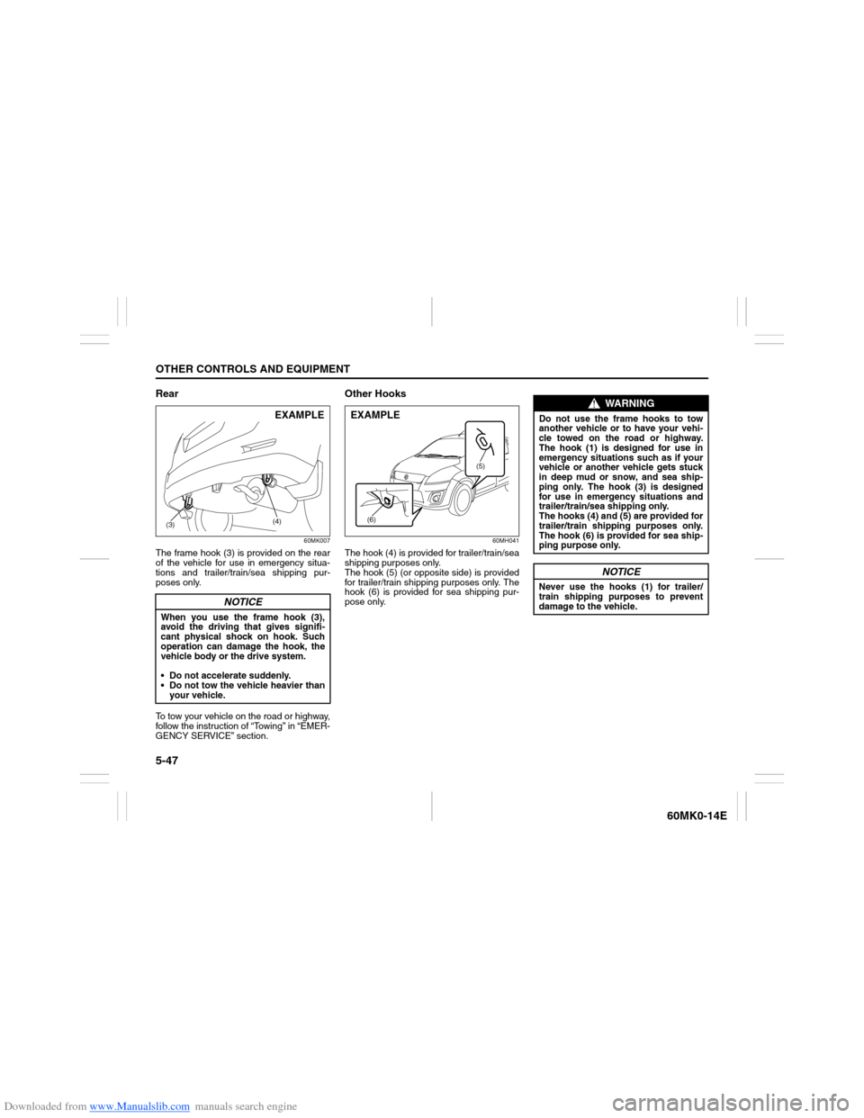
Rear
60MK007
The frame hook (3) is provided on the rear
of the vehicle for use in emergency situa-
tions and trailer/train/sea shipping pur-
poses only.
To tow your vehicle on the road or highway,
follow the instruction of “Towing” in “EMER-
GENCY SERVICE” section.
Other Hooks
60MH041
The hook (4) is provided for trailer/train/sea
shipping purposes only.
The hook (5) (or opposite side) is provided
for trailer/train shipping purposes only. The
hook (6) is provided for sea shipping pur-
pose only.
NOTICE
When you use the frame hook (3),
avoid the driving that gives signifi-
cant physical shock on hook. Such
operation can damage the hook, the
vehicle body or the drive system.
Do not accelerate suddenly.
Do not tow the vehicle heavier than
your vehicle.
(4)
(3)EXAMPLE
(5)
(6)
EXAMPLE
WARNING
Do not use the frame hooks to tow
another vehicle or to have your vehi-
cle towed on the road or highway.
The hook (1) is designed for use in
emergency situations such as if your
vehicle or another vehicle gets stuck
in deep mud or snow, and sea ship-
ping only. The hook (3) is designed
for use in emergency situations and
trailer/train/sea shipping only.
The hooks (4) and (5) are provided for
trailer/train shipping purposes only.
The hook (6) is provided for sea ship-
ping purpose only.
NOTICE
Never use the hooks (1) for trailer/
train shipping purposes to prevent
damage to the vehicle.
Page 146 of 207
Downloaded from www.Manualslib.com manuals search engine 7-1INSPECTION AND MAINTENANCE
60MK0-14E
60B128S
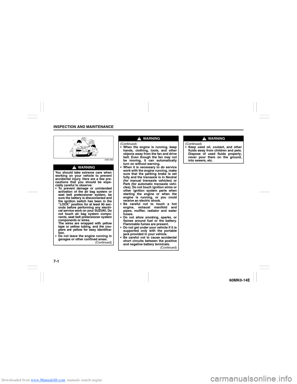
WARNING
You should take extreme care when
working on your vehicle to prevent
accidental injury. Here are a few pre-
cautions that you should be espe-
cially careful to observe:
To prevent damage or unintended
activation of the air bag system or
seat belt pretensioner system, be
sure the battery is disconnected and
the ignition switch has been in the
“LOCK” position for at least 90 sec-
onds before performing any electri-
cal service work on your SUZUKI. Do
not touch air bag system compo-
nents, seat belt pretensioner system
components or wires.
The wires are wrapped with yellow
tape or yellow tubing, and the cou-
plers are yellow for easy identifica-
tion.
Do not leave the engine running in
garages or other confined areas.
(Continued)
WARNING
(Continued)
When the engine is running, keep
hands, clothing, tools, and other
objects away from the fan and drive
belt. Even though the fan may not
be moving, it can automatically
turn on without warning.
When it is necessary to do service
work with the engine running, make
sure that the parking brake is set
fully and the transaxle is in Neutral
(for manual transaxle vehicles) or
Park (for automatic transaxle vehi-
cles). Do not touch ignition wires or
other ignition system parts when
starting the engine or when the
engine is running, or you could
receive an electric shock.
Be careful not to touch a hot
engine, exhaust manifold and
pipes, muffler, radiator and water
hoses.
Do not allow smoking, sparks, or
flames around fuel or the battery.
Flammable fumes are present.
Do not get under your vehicle if it is
supported only with the portable
jack provided in your vehicle.
Be careful not to cause accidental
short circuits between the positive
and negative battery terminals.
(Continued)
WARNING
(Continued)
Keep used oil, coolant, and other
fluids away from children and pets.
Dispose of used fluids properly;
never pour them on the ground,
into sewers, etc.
Page 147 of 207
Downloaded from www.Manualslib.com manuals search engine 7-2
INSPECTION AND MAINTENANCE
60MK0-14E
Maintenance ScheduleThe following table shows the times when
you should perform regular maintenance
on your vehicle. This table shows in miles,
kilometers and months when you should
perform inspections, adjustments, lubrica-
tion and other services. These intervals
should be shortened if driving is usually
done under severe conditions (refer to
“Maintenance Recommended under
Severe Driving Conditions”).
Periodic Maintenance
Schedule“R” : Replace or Change
“I” : Inspect, clean, adjust, lubricate
or replace as necessary
“L” : Lubricate
NOTE:
This table includes services as scheduled
up to 90000 km (54000 miles) mileage.
Beyond 90000 km (54000 miles), carry out
the same services at the same intervals
respectively.
WARNING
SUZUKI recommends that mainte-
nance on items marked with an aster-
isk (*) be performed by your
authorized SUZUKI dealer or a quali-
fied service technician. If you are
qualified, you may perform mainte-
nance on the unmarked items by
referring to the instructions in this
section. If you are not sure whether
you can successfully complete any of
the unmarked maintenance jobs, ask
your authorized SUZUKI dealer to do
the maintenance for you.
NOTICE
Whenever it becomes necessary to
replace parts on your vehicle, it is
recommended that you use genuine
SUZUKI replacement parts or their
equivalent.
Page 167 of 207
Downloaded from www.Manualslib.com manuals search engine 7-22
INSPECTION AND MAINTENANCE
60MK0-14E
To avoid uneven wear of your tires and to
prolong their life, rotate the tires as illus-
trated. Tires should be rotated every 10000
km (6000 miles). After rotation, adjust front
and rear tire pressures to the specification
listed on your vehicle’s Tire Information
Label.
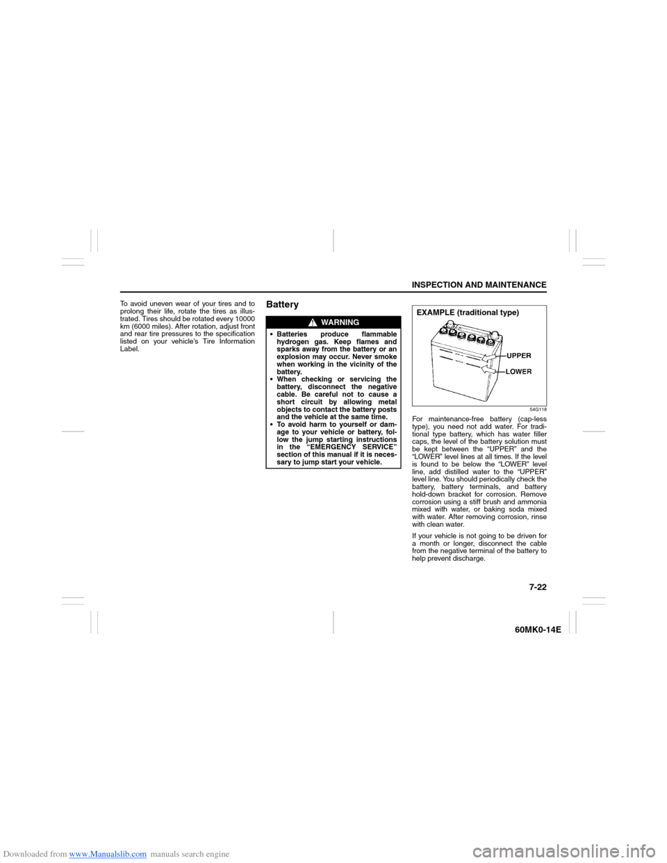
Battery
54G118
For maintenance-free battery (cap-less
type), you need not add water. For tradi-
tional type battery, which has water filler
caps, the level of the battery solution must
be kept between the “UPPER” and the
“LOWER” level lines at all times. If the level
is found to be below the “LOWER” level
line, add distilled water to the “UPPER”
level line. You should periodically check the
battery, battery terminals, and battery
hold-down bracket for corrosion. Remove
corrosion using a stiff brush and ammonia
mixed with water, or baking soda mixed
with water. After removing corrosion, rinse
with clean water.
If your vehicle is not going to be driven for
a month or longer, disconnect the cable
from the negative terminal of the battery to
help prevent discharge.
WARNING
Batteries produce flammable
hydrogen gas. Keep flames and
sparks away from the battery or an
explosion may occur. Never smoke
when working in the vicinity of the
battery.
When checking or servicing the
battery, disconnect the negative
cable. Be careful not to cause a
short circuit by allowing metal
objects to contact the battery posts
and the vehicle at the same time.
To avoid harm to yourself or dam-
age to your vehicle or battery, fol-
low the jump starting instructions
in the “EMERGENCY SERVICE”
section of this manual if it is neces-
sary to jump start your vehicle.
EXAMPLE (traditional type)
Page 181 of 207
Downloaded from www.Manualslib.com manuals search engine EMERGENCY SERVICE
8
60MK0-14E
60G411
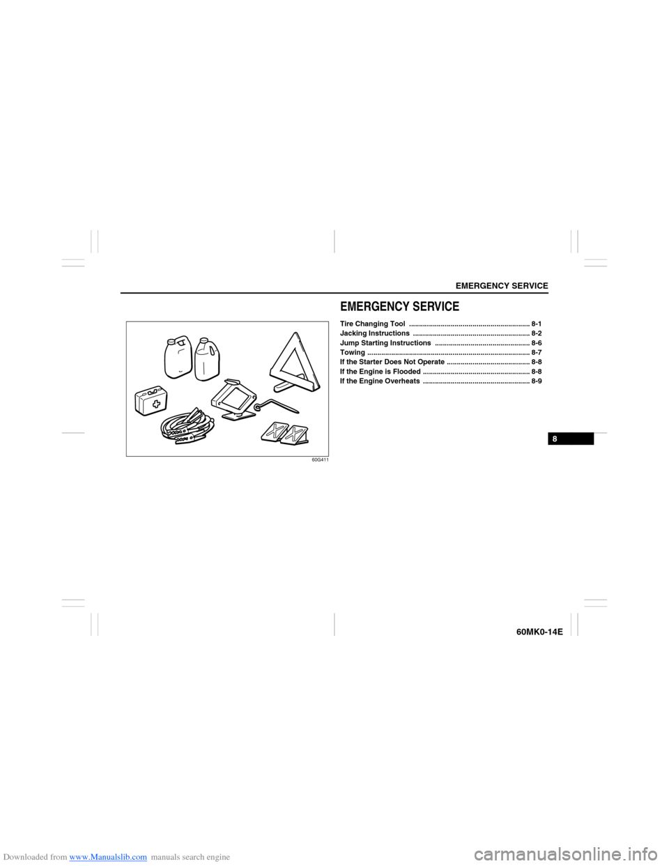
EMERGENCY SERVICETire Changing Tool ............................................................. 8-1
Jacking Instructions ........................................................... 8-2
Jump Starting Instructions ................................................ 8-6
Towing .................................................................................. 8-7
If the Starter Does Not Operate .......................................... 8-8
If the Engine is Flooded ...................................................... 8-8
If the Engine Overheats ...................................................... 8-9
Page 182 of 207
Downloaded from www.Manualslib.com manuals search engine 8-1EMERGENCY SERVICE
60MK0-14E
Tire Changing Tool
60MK031
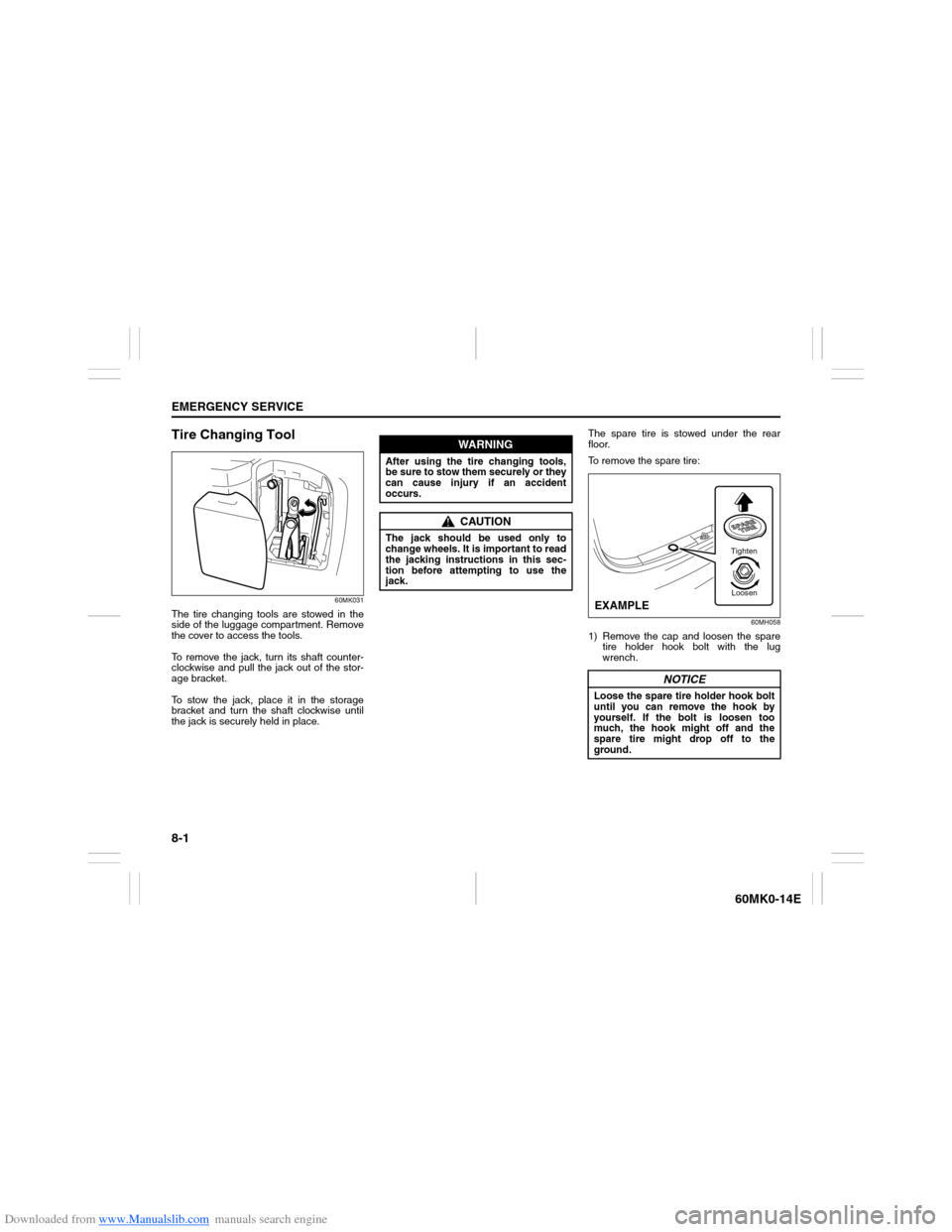
The tire changing tools are stowed in the
side of the luggage compartment. Remove
the cover to access the tools.
To remove the jack, turn its shaft counter-
clockwise and pull the jack out of the stor-
age bracket.
To stow the jack, place it in the storage
bracket and turn the shaft clockwise until
the jack is securely held in place.The spare tire is stowed under the rear
floor.
To remove the spare tire:
60MH058
1) Remove the cap and loosen the spare
tire holder hook bolt with the lug
wrench.
WARNING
After using the tire changing tools,
be sure to stow them securely or they
can cause injury if an accident
occurs.
CAUTION
The jack should be used only to
change wheels. It is important to read
the jacking instructions in this sec-
tion before attempting to use the
jack.
NOTICE
Loose the spare tire holder hook bolt
until you can remove the hook by
yourself. If the bolt is loosen too
much, the hook might off and the
spare tire might drop off to the
ground.
Tighten
Loosen
EXAMPLE
Page 183 of 207
Downloaded from www.Manualslib.com manuals search engine 8-2
EMERGENCY SERVICE
60MK0-14E
60MK010
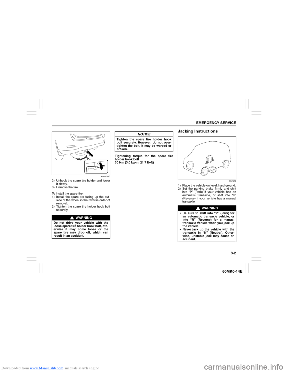
2) Unhook the spare tire holder and lower
it slowly.
3) Remove the tire.
To install the spare tire:
1) Install the spare tire facing up the out-
side of the wheel in the reverse order of
removal.
2) Tighten the spare tire holder hook bolt
securely.Tightening torque for the spare tire
holder hook bolt
30 Nm (3.0 kg-m, 21.7 lb-ft)
Jacking Instructions
75F062
1) Place the vehicle on level, hard ground.
2) Set the parking brake firmly and shift
into “P” (Park) if your vehicle has an
automatic transaxle, or shift into “R”
(Reverse) if your vehicle has a manual
transaxle.
WARNING
Do not drive your vehicle with the
loose spare tire holder hook bolt, oth-
erwise it may come loose or the
spare tire may drop off, which can
result in an accident.
NOTICE
Tighten the spare tire holder hook
bolt securely. However, do not over-
tighten the bolt, it may be warped or
broken.
WARNING
Be sure to shift into “P” (Park) for
an automatic transaxle vehicle, or
into “R” (Reverse) for a manual
transaxle vehicle when you jack up
the vehicle.
Never jack up the vehicle with the
transaxle in “N” (Neutral). Other-
wise, unstable jack may cause an
accident.
Page 184 of 207
Downloaded from www.Manualslib.com manuals search engine 8-3EMERGENCY SERVICE
60MK0-14E
3) Turn on the hazard warning flasher if
your vehicle is near traffic.
4) Block the front and rear of the wheel
diagonally opposite of the wheel being
lifted.
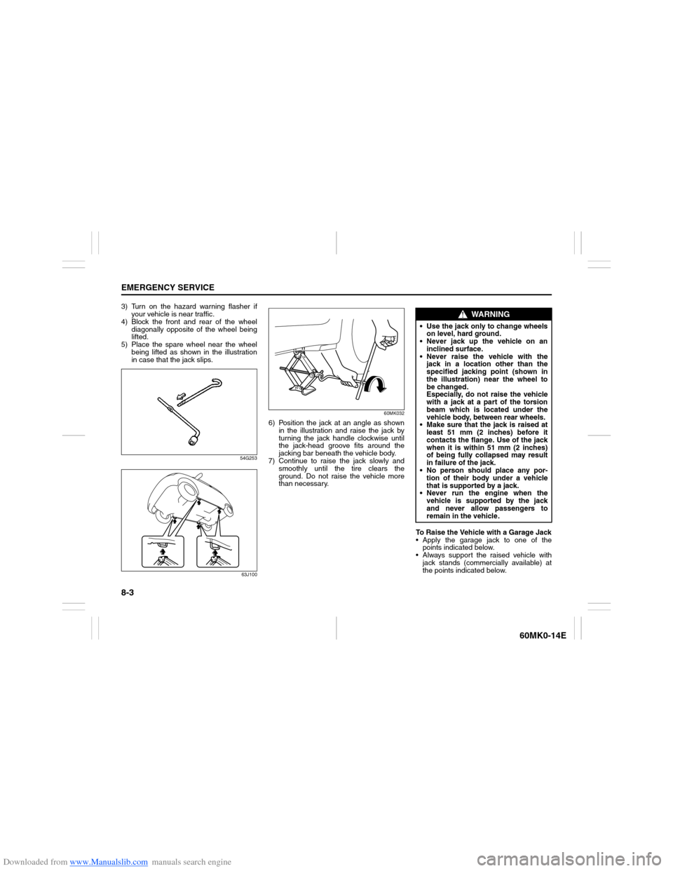
5) Place the spare wheel near the wheel
being lifted as shown in the illustration
in case that the jack slips.
54G253
63J10060MK032
6) Position the jack at an angle as shown
in the illustration and raise the jack by
turning the jack handle clockwise until
the jack-head groove fits around the
jacking bar beneath the vehicle body.
7) Continue to raise the jack slowly and
smoothly until the tire clears the
ground. Do not raise the vehicle more
than necessary.
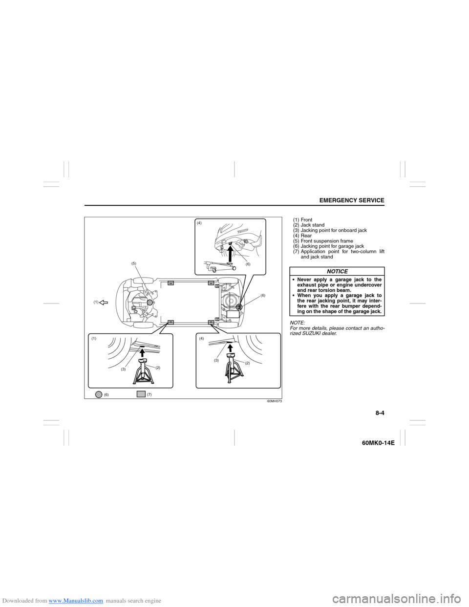
To Raise the Vehicle with a Garage Jack
Apply the garage jack to one of the
points indicated below.
Always support the raised vehicle with
jack stands (commercially available) at
the points indicated below.
WARNING
Use the jack only to change wheels
on level, hard ground.
Never jack up the vehicle on an
inclined surface.
Never raise the vehicle with the
jack in a location other than the
specified jacking point (shown in
the illustration) near the wheel to
be changed.
Especially, do not raise the vehicle
with a jack at a part of the torsion
beam which is located under the
vehicle body, between rear wheels.
Make sure that the jack is raised at
least 51 mm (2 inches) before it
contacts the flange. Use of the jack
when it is within 51 mm (2 inches)
of being fully collapsed may result
in failure of the jack.
No person should place any por-
tion of their body under a vehicle
that is supported by a jack.
Never run the engine when the
vehicle is supported by the jack
and never allow passengers to
remain in the vehicle.
Page 185 of 207
Downloaded from www.Manualslib.com manuals search engine 8-4
EMERGENCY SERVICE
60MK0-14E
60MH073
(1)
(1)
(2)(2)
(3)(4)
(5)
(6)(7)
(6)
(6)
(4)
(3)
(1) Front
(2) Jack stand
(3) Jacking point for onboard jack
(4) Rear
(5) Front suspension frame
(6) Jacking point for garage jack
(7) Application point for two-column lift
and jack stand
NOTE:
For more details, please contact an autho-
rized SUZUKI dealer.
NOTICE
Never apply a garage jack to the
exhaust pipe or engine undercover
and rear torsion beam.
When you apply a garage jack to
the rear jacking point, it may inter-
fere with the rear bumper depend-
ing on the shape of the garage jack.
Page 186 of 207
Downloaded from www.Manualslib.com manuals search engine 8-5EMERGENCY SERVICE
60MK0-14E
Changing WheelsTo change a wheel, use the following pro-
cedure:
1) Remove the jack, tools and spare wheel
from the vehicle.
2) Loosen, but do not remove the wheel
nuts.
3) Jack up the vehicle (follow the jacking
instructions in this section).
4) Remove the wheel nuts and wheel.
5) Before installing the new wheel, clean
any mud or dirt off from the surface of
the wheel and hub with a clean cloth.
Clean the hub carefully; it may be hot
from driving.
6) Install the new wheel and replace the
wheel nuts with their cone shaped end
facing the wheel. Tighten each nuts
snugly by hand until the wheel is
securely seated on the hub.
81A057
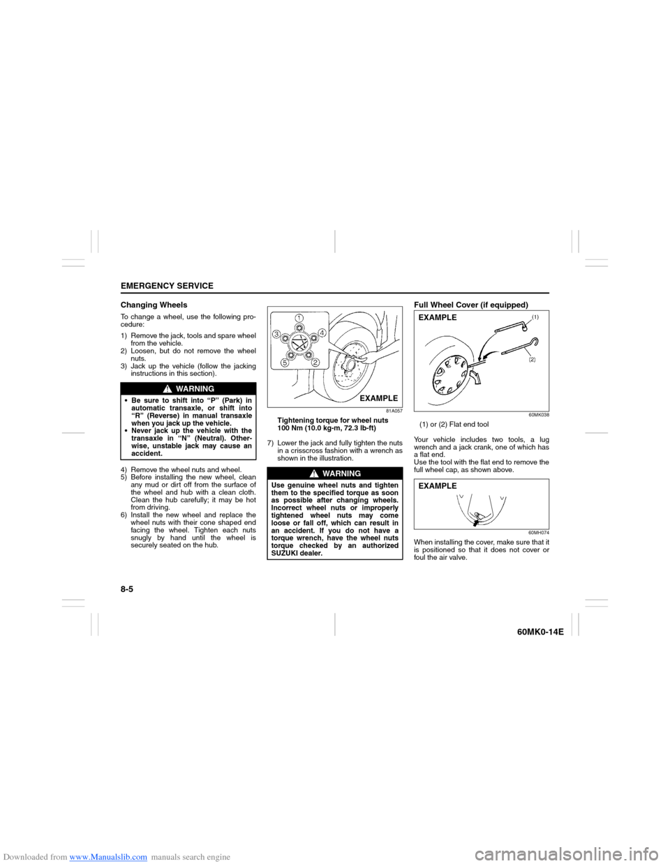
Tightening torque for wheel nuts
100 Nm (10.0 kg-m, 72.3 lb-ft)
7) Lower the jack and fully tighten the nuts
in a crisscross fashion with a wrench as
shown in the illustration.
Full Wheel Cover (if equipped)
60MK038
(1) or (2) Flat end tool
Your vehicle includes two tools, a lug
wrench and a jack crank, one of which has
a flat end.
Use the tool with the flat end to remove the
full wheel cap, as shown above.
60MH074
When installing the cover, make sure that it
is positioned so that it does not cover or
foul the air valve.
WARNING
Be sure to shift into “P” (Park) in
automatic transaxle, or shift into
“R” (Reverse) in manual transaxle
when you jack up the vehicle.
Never jack up the vehicle with the
transaxle in “N” (Neutral). Other-
wise, unstable jack may cause an
accident.
WARNING
Use genuine wheel nuts and tighten
them to the specified torque as soon
as possible after changing wheels.
Incorrect wheel nuts or improperly
tightened wheel nuts may come
loose or fall off, which can result in
an accident. If you do not have a
torque wrench, have the wheel nuts
torque checked by an authorized
SUZUKI dealer.
EXAMPLE
EXAMPLEEXAMPLE