drain bolt SUZUKI GRAND VITARA 1987 Service User Guide
[x] Cancel search | Manufacturer: SUZUKI, Model Year: 1987, Model line: GRAND VITARA, Model: SUZUKI GRAND VITARA 1987Pages: 962, PDF Size: 27.87 MB
Page 265 of 962
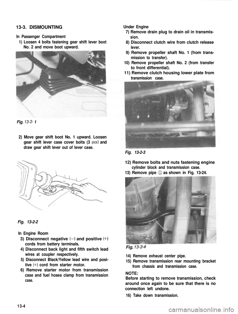
13-3. DISMOUNTINGIn Passenger Compartment
1) Loosen 4 bolts fastening gear shift lever boot
No. 2 and move boot upward.
Fig.
13-2- 1 Under Engine
7) Remove drain plug to drain oil in transmis-
sion.
8) Disconnect clutch wire from clutch release
lever.
9) Remove propeller shaft No. 1 (from trans-
mission to transfer).
10) Remove propeller shaft No. 2 (from transfer
to front differential).
11) Remove clutch housing lower plate from
transmission case.
2) Move gear shift boot No. 1 upward. Loosen
gear shift lever case cover bolts (3
PCS) and
draw gear shift lever out of lever case.
Fig. 13-2-3
Fig. 13-2-2 In Engine Room
3) Disconnect negative (-) and positive (+)
cords from battery terminals.
4) Disconnect back light and fifth switch lead
wires at coupler respectively.
5) Disconnect Black/Yellow lead wire and posi- tive
(+) cord from starter motor.
6) Remove starter motor from transmission
case and fuel hoses clamp from transmission
case.
12) Remove bolts and nuts fastening engine
cylinder block and transmission case.
13) Remove pipe (iJ as shown in Fig. 13-24.
Fig. 13-2-4
14) Remove exhaust center pipe.
15) Remove transmission rear mounting bracket
from chassis and transmission case.
NOTE:
Before starting to remove transmission, check
around once again to be sure that there is no
connection left undone.
16) Take down transmission.
13-4
Page 293 of 962
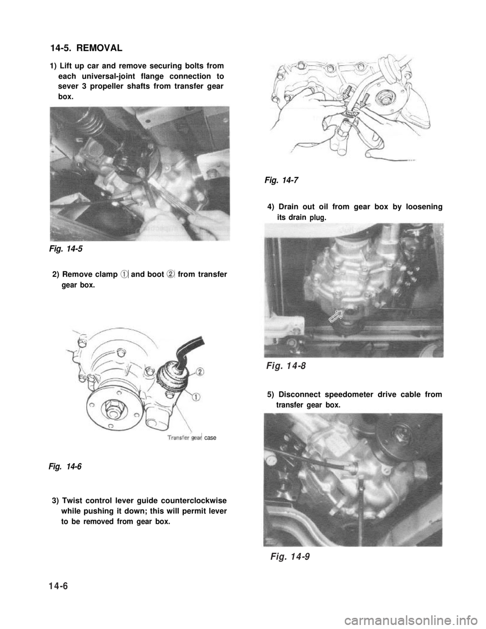
14-5. REMOVAL
1) Lift up car and remove securing bolts from
each universal-joint flange connection to
sever 3 propeller shafts from transfer gear
box.
Fig. 14-5
2) Remove clamp @ and boot @ from transfer
gear box.
Fig. 14-7
4) Drain out oil from gear box by loosening
its drainplug.
Fig. 14-8
5) Disconnect speedometer drive cable from
transfer gear box.
Transfer‘gear case
Fig. 14-6
3) Twist control lever guide counterclockwise
while pushing it down; this will permit lever
to be removed from gear box.
14-6
Fig. 14-8
Fig. 14-9
Page 310 of 962
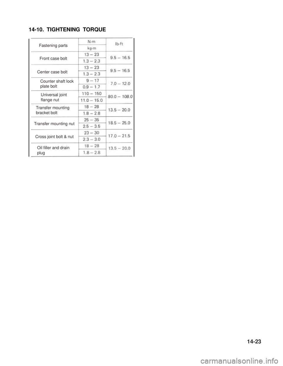
14-10. TIGHTENING TORQUE
Counter shaft lock
Universaljoint flange
Oil filler and drain
plug
Cross joint bolt & nut
Transfer mounting nut
Transfer mounting
bracket bolt
Universal joint
flange nut
Counter shaft lock
plate bolt
Center case bolt
Front case bolt
Fastening parts
14-23
Page 313 of 962
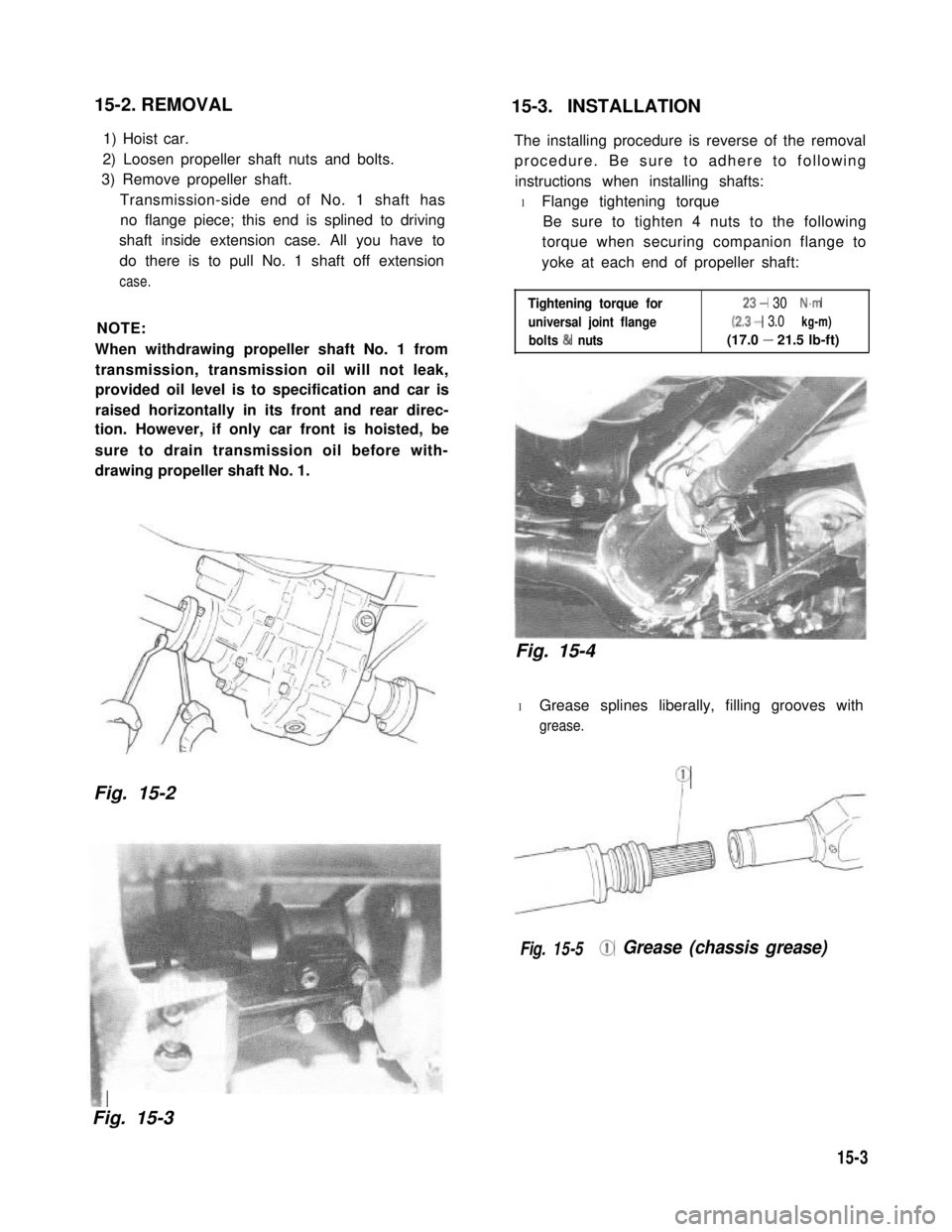
15-2. REMOVAL15-3. INSTALLATION
1) Hoist car.
2) Loosen propeller shaft nuts and bolts.
3) Remove propeller shaft.
Transmission-side end of No. 1 shaft has
no flange piece; this end is splined to driving
shaft inside extension case. All you have to
do there is to pull No. 1 shaft off extension
case.
NOTE:
When withdrawing propeller shaft No. 1 from
transmission, transmission oil will not leak,
provided oil level is to specification and car is
raised horizontally in its front and rear direc-
tion. However, if only car front is hoisted, be
sure to drain transmission oil before with-
drawing propeller shaft No. 1.
Fig. 15-2
The installing procedure is reverse of the removal
procedure. Be sure to adhere to following
instructions when installing shafts:
l Flange tightening torque
Be sure to tighten 4 nuts to the following
torque when securing companion flange to
yoke at each end of propeller shaft:
Tightening torque for
universal joint flange
bolts & nuts
23- 30 N.m
(2.3- 3.0 kg-m)
(17.0 - 21.5 lb-ft)
Fig. 15-4
l Grease splines liberally, filling grooves with
grease.
Q
Fig. 15-5@ Grease (chassis grease)
f&,a.
Fig. 15-3
15-3
Page 320 of 962
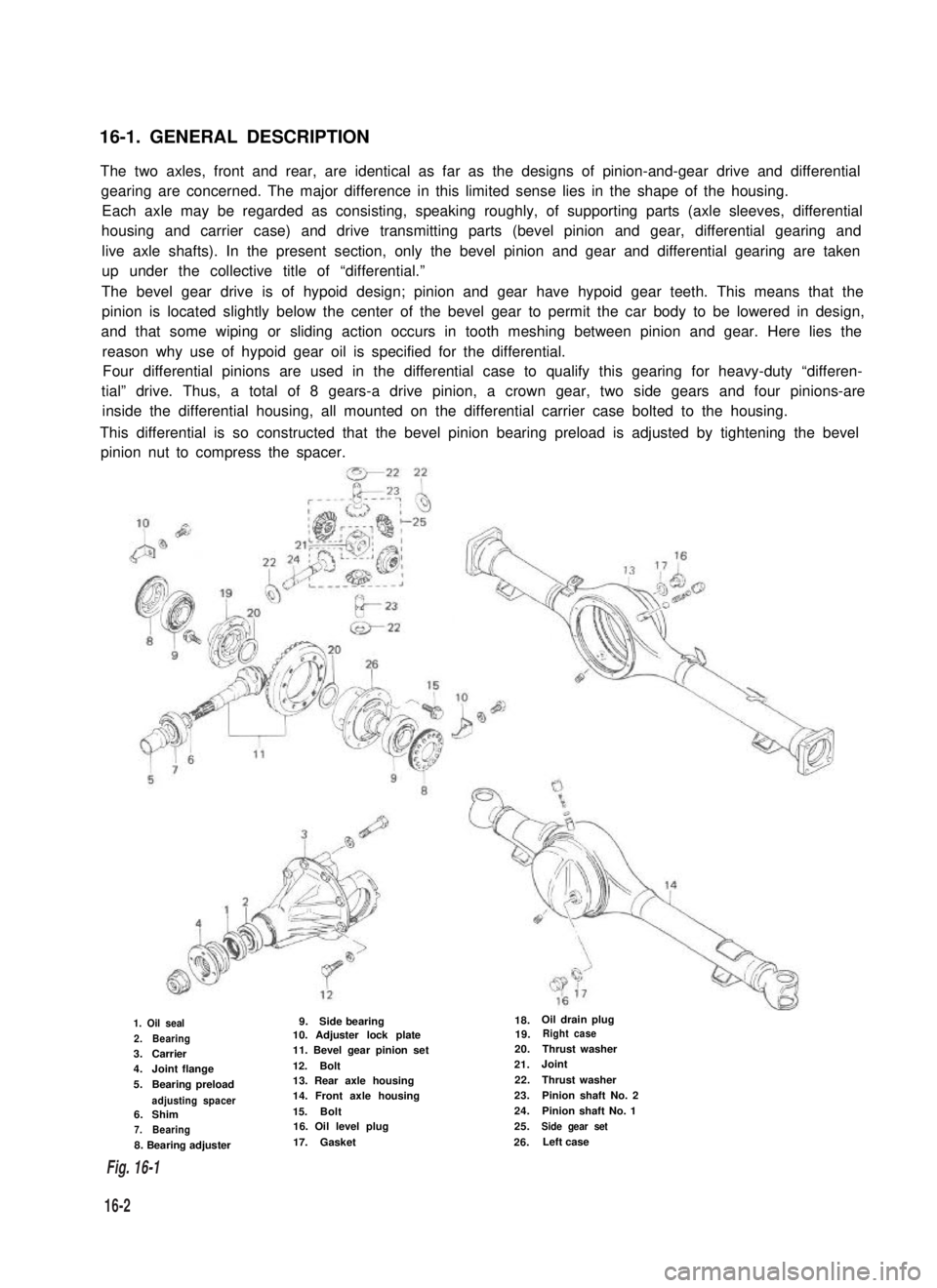
16-1. GENERAL DESCRIPTION
The two axles, front and rear, are identical as far as the designs of pinion-and-gear drive and differential
gearing are concerned. The major difference in this limited sense lies in the shape of the housing.
Each axle may be regarded as consisting, speaking roughly, of supporting parts (axle sleeves, differential
housing and carrier case) and drive transmitting parts (bevel pinion and gear, differential gearing and
live axle shafts). In the present section, only the bevel pinion and gear and differential gearing are taken
up under the collective title of “differential.”
The bevel gear drive is of hypoid design; pinion and gear have hypoid gear teeth. This means that the
pinion is located slightly below the center of the bevel gear to permit the car body to be lowered in design,
and that some wiping or sliding action occurs in tooth meshing between pinion and gear. Here lies the
reason why use of hypoid gear oil is specified for the differential.
Four differential pinions are used in the differential case to qualify this gearing for heavy-duty “differen-
tial” drive. Thus, a total of 8 gears-a drive pinion, a crown gear, two side gears and four pinions-are
inside the differential housing, all mounted on the differential carrier case bolted to the housing.
This differential is so constructed that the bevel pinion bearing preload is adjusted by tightening the bevel
pinion nut to compress the spacer.
1. Oil seal
2.Bearing3.Carrier4.Joint flange
5.Bearing preload
adjusting spacer6.Shim7.Bearing
8. Bearing adjuster
9.Side bearing10. Adjuster lock plate11. Bevel gear pinion set
12.Bolt13. Rear axle housing14. Front axle housing
15.Bolt16. Oil level plug
17.Gasket
18.Oil drain plug19.Right case
20.Thrust washer
21.Joint
22.Thrust washer
23.Pinion shaft No. 2
24.Pinion shaft No. 1
25.Side gear set
26.Left case
16-2
Fig. 16-1
Page 321 of 962
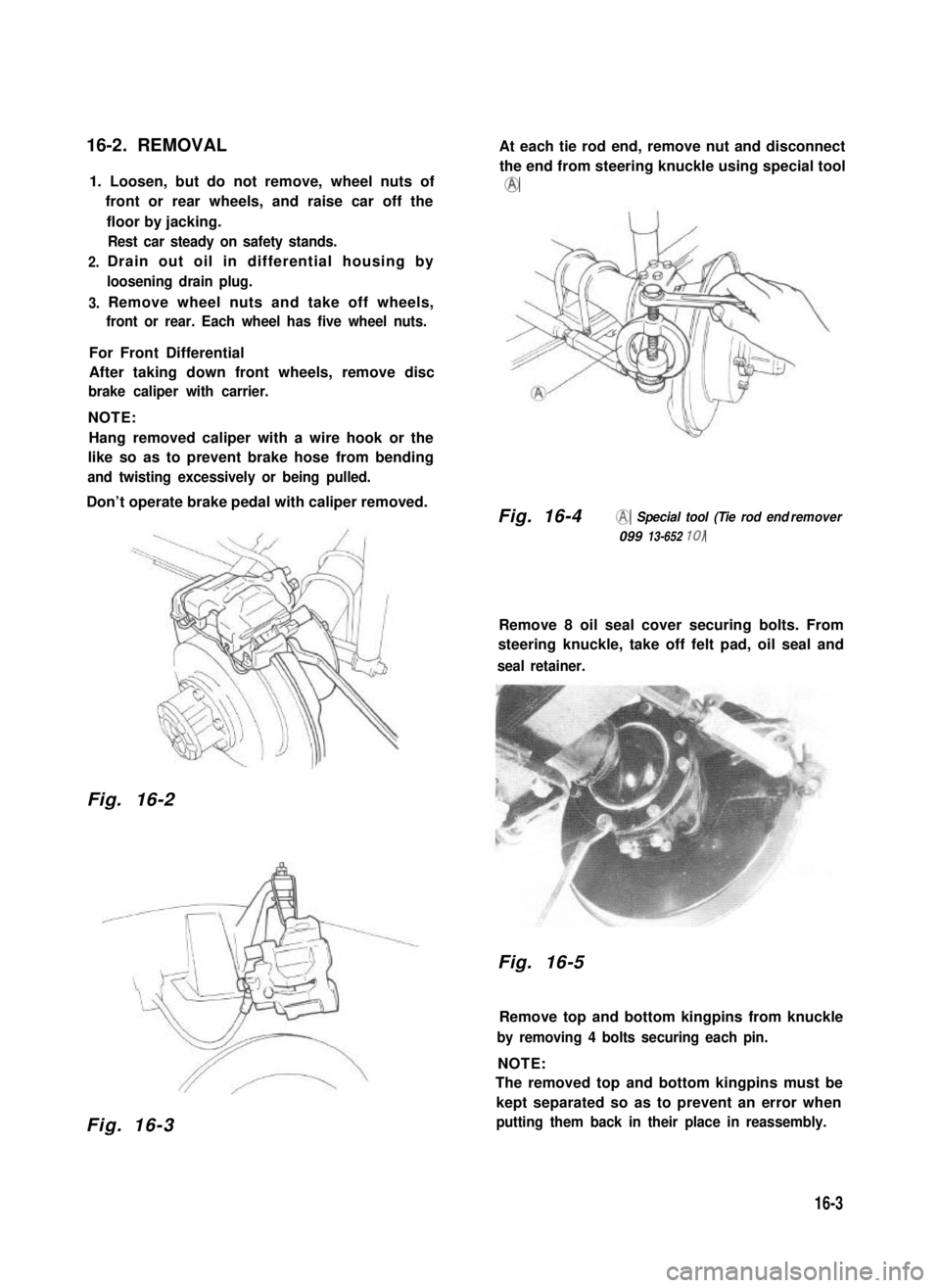
16-2. REMOVAL
1. Loosen, but do not remove, wheel nuts of
front or rear wheels, and raise car off the
2.
3.
floor by jacking.
Rest car steady on safety stands.
Drain out oil in differential housing by
loosening drain plug.
Remove wheel nuts and take off wheels,
front or rear. Each wheel has five wheel nuts.
For Front Differential
After taking down front wheels, remove disc
brake caliper with carrier.
NOTE:
Hang removed caliper with a wire hook or the
like so as to prevent brake hose from bending
and twisting excessively or being pulled.
Don’t operate brake pedal with caliper removed.
Fig. 16-2
Fig. 16-3
At each tie rod end, remove nut and disconnect
the end from steering knuckle using special tool
@
Fig. 16-4@ Special tool (Tie rod end remover
099 13-652 10)
Remove 8 oil seal cover securing bolts. From
steering knuckle, take off felt pad, oil seal and
seal retainer.
Fig. 16-5
Remove top and bottom kingpins from knuckle
by removing 4 bolts securing each pin.
NOTE:
The removed top and bottom kingpins must be
kept separated so as to prevent an error when
putting them back in their place in reassembly.
16-3
Page 334 of 962

16-7. MAINTENANCE SERVICES
Inspection
Inspect differential and differential housing for
evidence of oil leakage.
Oil level ‘is checked by means of its oil level
plug. Refer to p 1-20 for level inspection,
Fig. 16-33 @ Drain plug
CD Oil level & filler plug
Oil Change
1 ) Remove oil drain plug and drain oil.
2) Reinstall drain plug and tighten it to specified
tightening torque.
3) Remove oil level & filler plug and fill diffe-
rential housing with new specified oil.
Differential oilHypoid gear oil
specificationSAE 8OW-90,75W-80 or 75W-90
OilFront2.0 litres (4.2/3.5 US/Imp pt.)
capacityRear1.5 litres (3.2/2.6 US/Imp pt.)
It is highly recommended to use SAE 75W-90
gear oil.
For viscosity chart, refer to P. 1-20.
16-8. RECOMMENDED TORQUE
SPECIFICATIONS
ITightening torqueI
IFastening partsN.m1 kg-m 11
Side bearing capbolt70- 1007.0-10.051 .O-72.0
Drive bevel gearbolt80- 908.0-9.058.0-66.0
Differential casebolt37-453.7-4.527.0-32.5I
4) Reinstall oil level & filler plug and tighten it
to specified tightening torque.
16-16
Side bearing adjusterlock bolt
Differential carrier bolt
Oil level & filler plug
Oil drain plug
Page 350 of 962
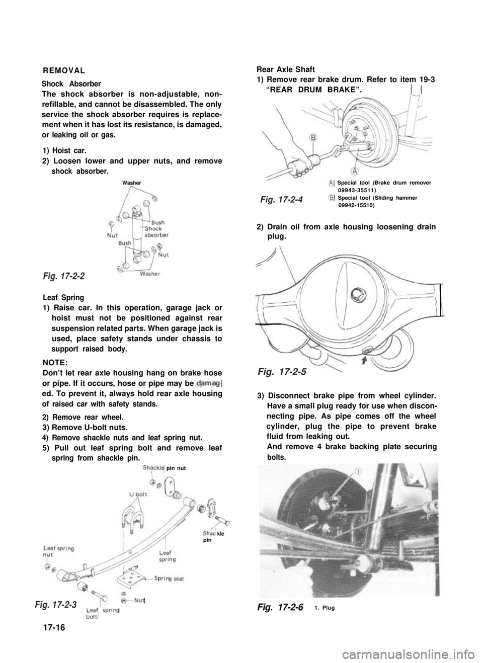
REMOVALRear Axle Shaft
Shock Absorber
The shock absorber is non-adjustable, non-
refillable, and cannot be disassembled. The only
service the shock absorber requires is replace-
ment when it has lost its resistance, is damaged,
or leaking oil or gas.
1) Remove rear brake drum. Refer to item 19-3
“REAR DRUM BRAKE”.I /
1) Hoist car.
2) Loosen lower and upper nuts, and remove
shock absorber.
Washer@ Special tool (Brake drum remover09943-35511)
Leaf Spring
1) Raise car. In this operation, garage jack or
hoist must not be positioned against rear
suspension related parts. When garage jack is
used, place safety stands under chassis to
support raised body.
NOTE:
Don’t let rear axle housing hang on brake hose
or pipe. If it occurs, hose or pipe may be d,amag-
ed. To prevent it, always hold rear axle housing
of raised car with safety stands.
2) Remove rear wheel.
3) Remove U-bolt nuts.
4) Remove shackle nuts and leaf spring nut.
5) Pull out leaf spring bolt and remove leaf
spring from shackle pin.
ShTckle pin nut
Sha’, klepin
@Special tool (Sliding hammer09942-15510)
2) Drain oil from axle housing loosening drain
plug.
3) Disconnect brake pipe from wheel cylinder.
Have a small plug ready for use when discon-
necting pipe. As pipe comes off the wheel
cylinder, plug the pipe to prevent brake
fluid from leaking out.
And remove 4 brake backing plate securing
bolts.
*Nut
;-; wring
17-16
Fig. 17-2-61. Plug
Fig. 17-2-2
Fig. 17-2-3
Fig. 17-2-4
Fig. 17-2-5