drain bolt SUZUKI GRAND VITARA 1987 Service Repair Manual
[x] Cancel search | Manufacturer: SUZUKI, Model Year: 1987, Model line: GRAND VITARA, Model: SUZUKI GRAND VITARA 1987Pages: 962, PDF Size: 27.87 MB
Page 25 of 962

CAUTION:
When changing engine coolant, use mixture
of 56% water and 50% GOLDEN CRUISER
1200for the market where ambient tem-
perature falls lower than -16°C (3°F) in
winter and mixture of 70% water and
30% GOLDEN CRUISER 1200for the
market where ambient temperature doesn’t
fall lower than -16°C (3” F).
Even in a market where no freezing tempe-
rature is anticipated, mixture of 70% water
and 30% GOLDEN CRUISER 1200
should be used for the purpose of corro-
sion protection and lubrication.
7. EXHAUST PIPES AND MOUNTINGS
INSPECTION
1.Drain plug
1. Reservoir tank cap2. Reservoir tank
3. Arrow marks
5) Fill radiator with specified amount of coolant,
and run engine for 2 or 3 minutes at idle.
This drives out any air which may still be
trappedwithincoolingsystem.STOP
ENGINE. Add coolant as necessary until
coolant level reaches the filler throat of
radiator. Reinstall radiator cap.
6) Add coolant to reservoir tank so that the level
aligns with Full mark. Then, reinstall cap
aligning the arrow marks on the tank and cap.
r.
COOLANT CAPACITY
Engine, radiator and4.2 liters
heater(8.9/7.4 US/Imp pt.)
Reservoir tank0.6 liters
(1.3/1.1 US/Imp pt.)
ITotal4.8 liters
(10.1/8.4US/lmp pt.)
WARNING:
To avoid danger of being burned, do not
touch exhaust system when system is hot.
Any service on exhaust system should be
performed when system is cool.
When carrying out periodic maintenance, or the
car is raised for other service, check exhaust
system as follows:
l Check rubber mountings for damage, deterio-
ration, and out of position.
l Check exhaust system for leakage, loose
connections, dents, and damages.
If bolts or nuts are loose, tighten them to
specification. Refer to below chart for torque
specification.
l Check nearby body areas for damaged, miss-
ing, or mispositioned parts, open seams,
holes, loose connections or’ other defects
which could permit exhaust fumes to seep
into the car.
l Make sure that exhaust system components
have enough clearance from the underbody to
avoid overheating and possible damage to the
floor carpet.
l Any defects should be fixed at once.
IBolts and nutTightening torqueI
40-80 N-m
Exhaustpipebolts4.0-6.0 kg-m
29.0-43.0 lb-ft
Muffler nuts
18 - 28 N-m
1.8 - 2.8 kg-m
13.5 - 20.0 lb-ft
Replace center pipe rubber mounting and muffler
rubber mountings with new ones periodically.
l-9
Page 36 of 962
3) Check propeller shaft (No. 1, No. 2, No. 3)
flange yoke bolts for tightness, and retighten
them as necessary:
N.mkg-mlb-ftTighteningtorque23-302.3-3.017.0-21.5
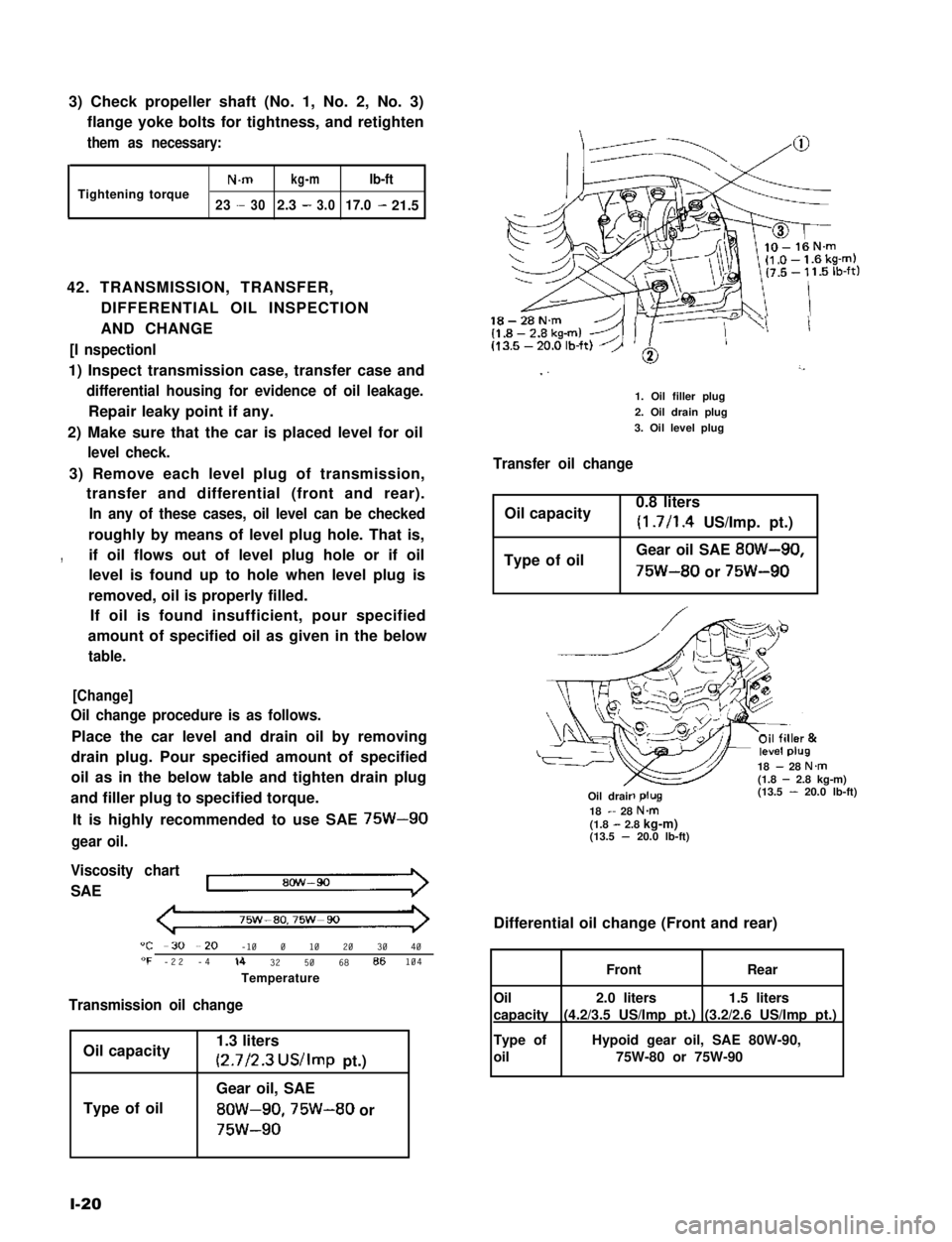
42. TRANSMISSION, TRANSFER,
DIFFERENTIAL OIL INSPECTION
AND CHANGE
[I nspectionl
1) Inspect transmission case, transfer case and
differential housing for evidence of oil leakage.
Repair leaky point if any.
2) Make sure that the car is placed level for oil
level check.
3) Remove each level plug of transmission,
transfer and differential (front and rear).
In any of these cases, oil level can be checked
roughly by means of level plug hole. That is,
,if oil flows out of level plug hole or if oil
level is found up to hole when level plug is
removed, oil is properly filled.
If oil is found insufficient, pour specified
amount of specified oil as given in the below
table.
[Change]
Oil change procedure is as follows.
Place the car level and drain oil by removing
drain plug. Pour specified amount of specified
oil as in the below table and tighten drain plug
and filler plug to specified torque.
It is highly recommended to use SAE 75W-90
gear oil.
Viscosity chart
SAE
75w-ao,75w-90
"C -30 --20 -10 0 10 20 30 40"F -22 -4lb 32 50 68 86104
Temperature
Transmission oil change
Oil capacity
Type of oil
1.3 liters
(2.7/2.3 US/Imp pt.)
Gear oil, SAE
8OW-90,75W-80 or
75w-90
l-20
18-28N.m
I ”’
1. Oil filler plug
2. Oil drain plug
3. Oil level plug
Transfer oil change
Oil capacity0.8 liters
(1.7/l .4 US/Imp. pt.)
Type of oilGear oil SAE 8OW-90,
75W-80 or 75W-90
18 - 28 N.m(1.8 - 2.8 kg-m)(13.5 - 20.0 lb-ft)-R-Oil drair18 - 28 N&(1.8 - 2.8 kg-m)(13.5 - 20.0 lb-ft)
Differential oil change (Front and rear)
1.5 liters
(3.2/2.6 US/Imp pt.)
2.0 liters
(4.2/3.5 US/Imp pt.)
FrontRear
Oil
capacity
Type of
oil
Hypoid gear oil, SAE 80W-90,
75W-80 or 75W-90
Page 37 of 962
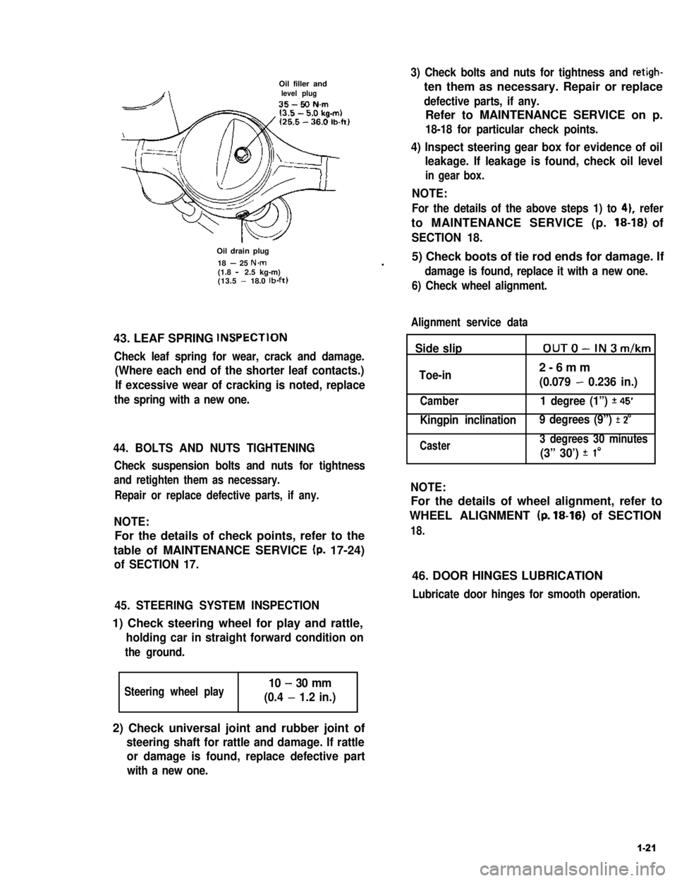
Oil filler andlevel plug
Oil drain plug
18 - 25 N.m(1.8 - 2.5 kg-m)(13.5 - 18.0 lb-ft)
43. LEAF SPRING lNSPECTlON
Check leaf spring for wear, crack and damage.
(Where each end of the shorter leaf contacts.)
If excessive wear of cracking is noted, replace
the spring with a new one.
44. BOLTS AND NUTS TIGHTENING
Check suspension bolts and nuts for tightness
and retighten them as necessary.
Repair or replace defective parts, if any.
NOTE:
For the details of check points, refer to the
table of MAINTENANCE SERVICE (p. 17-24)
of SECTION 17.
45. STEERING SYSTEM INSPECTION
1) Check steering wheel for play and rattle,
holding car in straight forward condition on
the ground.
Steering wheel play10 - 30 mm
(0.4 - 1.2 in.)
3) Check bolts and nuts for tightness and retigh-
ten them as necessary. Repair or replace
defective parts, if any.
Refer to MAINTENANCE SERVICE on p.
18-18 for particular check points.
4) Inspect steering gear box for evidence of oil
leakage. If leakage is found, check oil level
in gear box.
NOTE:
For the details of the above steps 1) to 41, refer
to MAINTENANCE SERVICE (p. 18-18) of
SECTION 18.
.5) Check boots of tie rod ends for damage. If
damage is found, replace it with a new one.
6) Check wheel alignment.
Alignment service data
Side slipOUTO-IN3m/km
Toe-in2-6mm
(0.079 - 0.236 in.)
Camber1 degree (1”) *45’
Kingpin inclination 9 degrees (9”) f 2’
Caster3 degrees 30 minutes
(3” 30’) f I0
NOTE:
For the details of wheel alignment, refer to
WHEEL ALIGNMENT (p. 18-16) of SECTION
18.
46. DOOR HINGES LUBRICATION
Lubricate door hinges for smooth operation.
2) Check universal joint and rubber joint of
steering shaft for rattle and damage. If rattle
or damage is found, replace defective part
with a new one.
1-21
Page 46 of 962

ConditionPossible causeCorrection
High fuel consumptionAbnormal condition ignition system
1. Improper ignition timingAdjust
2. Leak or loose connection of high tension cordRepair or replace
3. Defective spark plug (improper gap, heavyClean, adjust or replace
deposits, and burned electrodes, etc..)
4. Cracked distributor cap or rotorReplace
5. Malfunctioning mechanical and vacuumCheck and repair or
advancers in distributorreplace
Abnormal condition in fuel system
1. Improper float levelAdjust
2. Fuel leakage from tank, pipe or carburetorRepair or replace
3. Malfunctioning carburetor choke systemRepair or replace
4. Dirty or clogged carburetor jetsClean
5. Clogged air cleaner elementClean or replace
6. Malfunctioning thermostatically controlledCheck and repair or
air cleanerreplace
Abnormal condition in engine
1. Low compressionPreviously outlined
2. Poor valve seatingRepair or replace
3. Improper valve clearanceAdjust
Emission control
1. Air leaks at exhaust manifoldTighten manifold bolts
and nuts.
Replace gasket.
2. Oxygen sensor out of orderReplace.
3. Water temperature switch out of orderReplace.
4. Malfunctioning throttle position switchReplace
5. Malfunctioning MCS (mixture controlReplace
solenoid) valve in carburetor
6. Malfunctioning EGR valveReplace
Others
1. Dragging brakesRepair or replace
2. Slipping clutchAdjust or replace
3. Improper tire pressureAdjust
Excessive engine oilOil leakage
consumption1. Loose oil drain plugTighten
2. Loose oil pan securing boltsTighten
3. Deteriorated or broken oil pan sealantReplace sealant
4. Leaky oil sealsReplace
5. Blown cylinder head gasketReplace
6. Improper tightening of oil filterTighten
7. Loose oil pressure switchTighten
2-8
Page 64 of 962
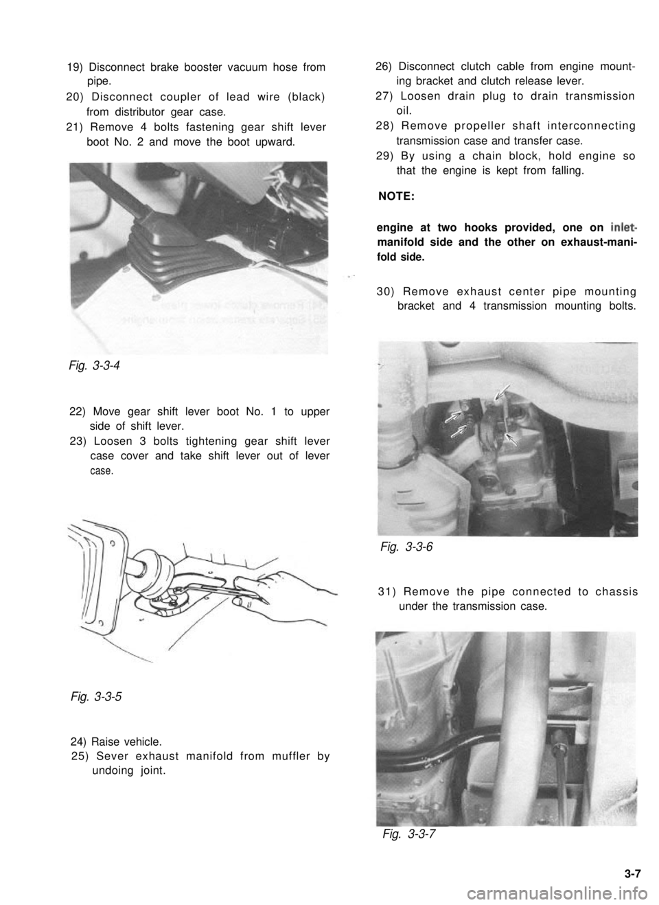
19) Disconnect brake booster vacuum hose from
pipe.
20) Disconnect coupler of lead wire (black) from distributor gear case.
21) Remove 4 bolts fastening gear shift lever boot No. 2 and move the boot upward.Fig. 3-3-4
22) Move gear shift lever boot No. 1 to upperside of shift lever.
23) Loosen 3 bolts tightening gear shift lever case cover and take shift lever out of lever
case.
26) Disconnect clutch cable from engine mount- ing bracket and clutch release lever.
27) Loosen drain plug to drain transmission oil.
28) Remove propeller shaft interconnecting transmission case and transfer case.
29) By using a chain block, hold engine so that the engine is kept from falling.
NOTE:
engine at two hooks provided, one on
inlet-
manifold side and the other on exhaust-mani-
fold side.
30) Remove exhaust center pipe mounting bracket and 4 transmission mounting bolts.
Fig. 3-3-6
31) Remove the pipe connected to chassis
under the transmission case.
Fig. 3-3-5
24) Raise vehicle.25) Sever exhaust manifold from muffler by undoing joint.
Fig. 3-3-7
3-7
Page 66 of 962
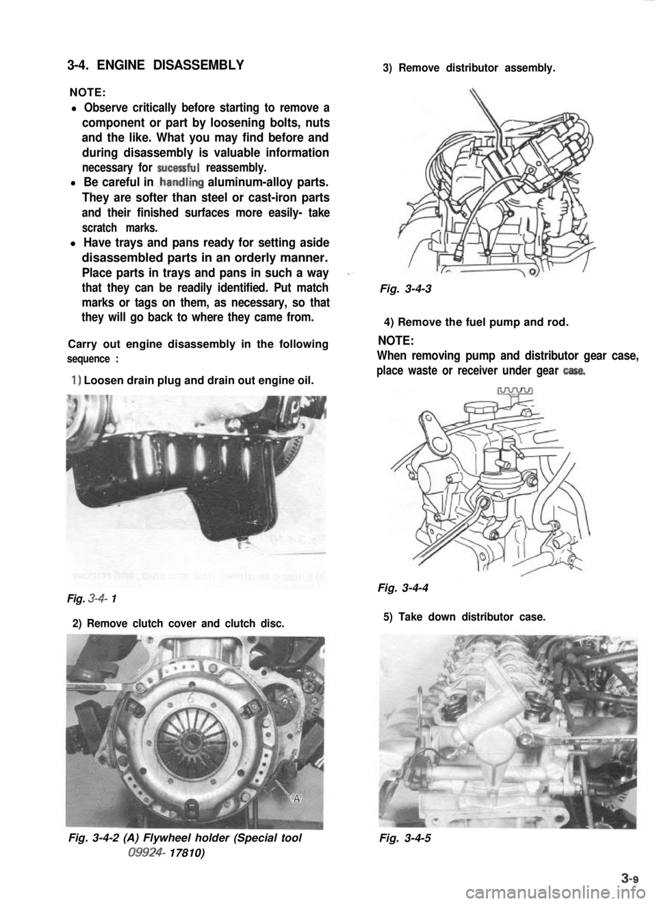
3-4. ENGINE DISASSEMBLY
NOTE:
3) Remove distributor assembly.
l Observe critically before starting to remove a
component or part by loosening bolts, nuts
and the like. What you may find before and
during disassembly is valuable information
necessary for sucessful reassembly.
l Be careful in .handling aluminum-alloy parts.
They are softer than steel or cast-iron parts
and their finished surfaces more easily- take
scratch marks.
l Have trays and pans ready for setting aside
disassembled parts in an orderly manner.
Place parts in trays and pans in such a way_.
that they can be readily identified. Put matchFig. 3-4-3
marks or tags on them, as necessary, so that
they will go back to where they came from.
4) Remove the fuel pump and rod.
Carry out engine disassembly in the following
NOTE:
sequence :When removing pump and distributor gear case,
1) Loosen drain plug and drain out engine oil.place waste or receiver under gear casa.
Fig. 3-4-4Fig. 3-4- 1
2) Remove clutch cover and clutch disc. 5) Take down distributor case.
Fig. 3-4-2 (A) Flywheel holder (Special tool09924-
17810) Fig. 3-4-5
Page 99 of 962
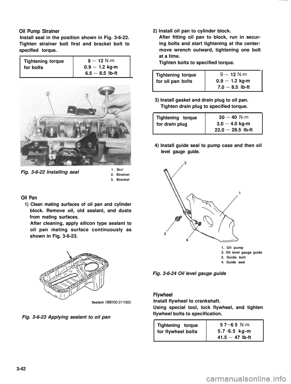
Oil Pump Strainer
Install seal in the position shown in Fig. 3-6-22.
Tighten strainer bolt first and bracket bolt to
specified torque.
Tighteningtorque9-12 N.m
0.9-for bolts1.2 kg-m
6.5 -8.5 lb-ft
Fig. 3-6-22 Installing seal1. Seal
2. Strainer
3. Bracket
Oil Pan
1) Clean mating surfaces of oil pan and cylinder
block. Remove oil, old sealant, and dusts
from mating surfaces.
After cleaning, apply silicon type sealant to
oil pan mating surface continuously as
shown in Fig. 3-6-23.
Sealant MOOO-31150)
Fig. 3-6-23 Applying sealant to oil pan
2) Install oil pan to cylinder block.
After fitting oil pan to block, run in secur-
ing bolts and start tightening at the center:
move wrench outward, tightening one bolt
at a time.
Tighten bolts to specified torque.
Tighteningtorque9-12 N-m
-for oil panbolts0.91.2 kg-m
7.0 -8.5 lb-ft
3) Install gasket and drain plug to oil pan.
Tighten drain plug to specified torque.
Tightening torque
for drain plug
30-40 N.m
3.0-4.0 kg-m
22.0-28.5 lb-ft
4) Install guide seal to pump case and then oil
level gauge guide.
1. Oil pump2. Oil level gauge guide
3. Guide bolt
4. Guide seal
Fig. 3-6-24 Oil level gauge guide
Flywheel
Install flywheel to crankshaft.
Using special tool, lock flywheel, and tighten
flywheel bolts to specification.
Tightening torque
for flywheel bolts
57 65 N-m-
5.7 6.5 kg-m-
41.5 - 47 lb-ft
3-42
Page 115 of 962
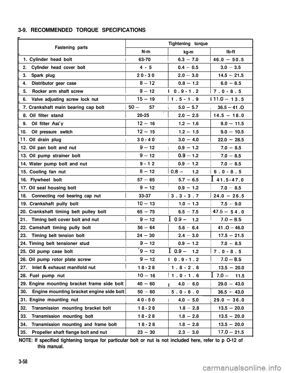
3-9. RECOMMENDED TORQUE SPECIFICATIONS
Fastening partsN-m
Tightening torque
kg-mlb-ft
1. Cylinder head bolt1 63-7016.3 - 7.01 46.0 - 50.5
2.Cylinder head cover bolt4-50.4-0.53.0-3.5
3.Spark plug20-302.0-3.014.5-21.5
4.Distributor gear case8-120.8-1.26.0-8.5
5.Rocker arm shaft screwI9- 12I 0.9-1.21 7.0-8.5
6.Valve adjusting screw lock nut
7. Crankshaft main bearing cap bolt
8. Oil filter stand
I15- 191 1.5-1.9I ll.O- 13.5
1 50- 5715.0 - 5.7136.5 - 41 .O
I20-25 -. 12.0 - 2.51 14.5 - 18.0
9.Oilfilter Ass’y12-161.2-1.69.0-11.5
10.Oilpressure switch12-151.2-1.59.0-10.5
11. Oil drain plugI30-40I3.0 - 4.0122.0 - 28.5
12. Oil pan bolt and nutI9- 12I0.9 - 1.2I7.0 - 8.5
13. Oil pump strainer bolt
14. Water pump bolt and nut
I9- 12I0.9 - 1.2I7.0 - 8.5
I9-12I0.9 - 1.2I7.0 - 8.5
15. Cooling fan nutI8- 121 0.8- 1.21 6.0-8.5
16. Flywheel boltI57 - 65I5.7 - 6.5I 41.5-47.0
17. Oil seal housing boltI9- 12I0.9 - 1.2I7.0 - 8.5
18.Connecting rod bearing cap nut1 33-37( 3.3-3.71 24.0 - 26.5
19. Crankshaft pully boltIlo- 13I1.0 - 1.3I7.5 - 9.0
20. Crankshaft timing belt pulley bolt
21.Timing belt cover bolt and nut
I65 - 75I6.5 - 7.51 47.5- 54.0
I9- 12I 0.9- 1.21 7-O-8.5
22. Camshaft timing pully boltI56 - 6415.6 - 6.4141 .O - 46.0III
23.Timingbelttensionbolt24-302.4-3.0117.5-21.5
24. Timing belt tensioner studI9- 12I0.9 - 1.2I7.0 - 8.5
25. Oil pump case boltI‘9- 12I 0.9- 1.21 7.0-8.5
26. Oil pump rotor plate screwI9- 12I 0.9-1.21 7-O-8.5
27.Inlet & exhaust manifold nutI18-281 1.8-2.8I13.5 - 20.0
28. Fuel pump nutIlo- 161 1.0-1.6I 7.0- 11.5
29. Engine mounting bracket frame side bolt 140 - 60I ~~~4.0 - 6.0129.0 - 43.0
30.Engine mounting bracket engine side bolt I50 - 601 5.0-6.0136.5 - 43.0
31. Engine mounting nutI40-50I4.0 - 5.01 29.0 - 36.0I1I
32.Transmissionmountingbracketbolt18-281.8-2.8113.5-20.0
33.Transmission mounting bolt18-281.8-2.813.5 -20.0
34.Transmission mounting and framebolt18-281.8-2.813.5 -20.0
35.Propeller shaft flange bolt and nut23 - 302.3-3.017.0-21.5
NOTE: If specified tightening torque for particular bolt or nut is not included here, refer to p O-12 of
this manual.
3-58
Page 195 of 962
6-2. .REMOVAL
WARNING:
l Check to make sure that cooling water
temperature is cold before removing any
part of cooling system components.
l Also be sure to disconnect 0 cord from
battery 0 terminal before removing any
part.
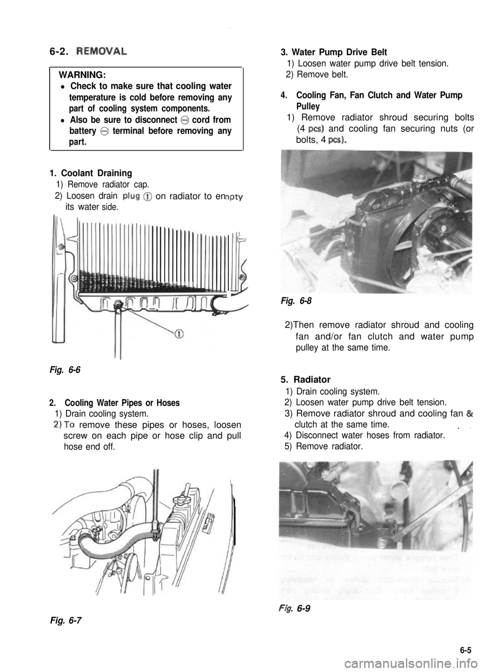
1. Coolant Draining
1) Remove radiator cap.
2) Loosen drain
its waterside.
-on radiator to enPtY
-
Illi
Fig. 6-6
2.Cooling Water Pipes or Hoses
1) Drain cooling system.
2)To remove these pipes or hoses, loosen
screw on each pipe or hose clip and pull
hose end off.
3. Water Pump Drive Belt
1) Loosen water pump drive belt tension.
2) Remove belt.
4.Cooling Fan, Fan Clutch and Water Pump
Pulley
1) Remove radiator shroud securing bolts
(4 PCS) and cooling fan securing nuts (or
bolts, 4 pcs).
Fig. 6-8
2)Then remove radiator shroud and cooling
fan and/or fan clutch and water pump
pulley at the same time.
5. Radiator
1) Drain cooling system.
2) Loosen water pump drive belt tension.
3) Remove radiator shroud and cooling fan &
clutch at the same time.. ”
4) Disconnect water hoses from radiator.
5) Remove radiator.
FI& 6-9
Fig. 6-7
6-5
Page 196 of 962
6. Thermostat
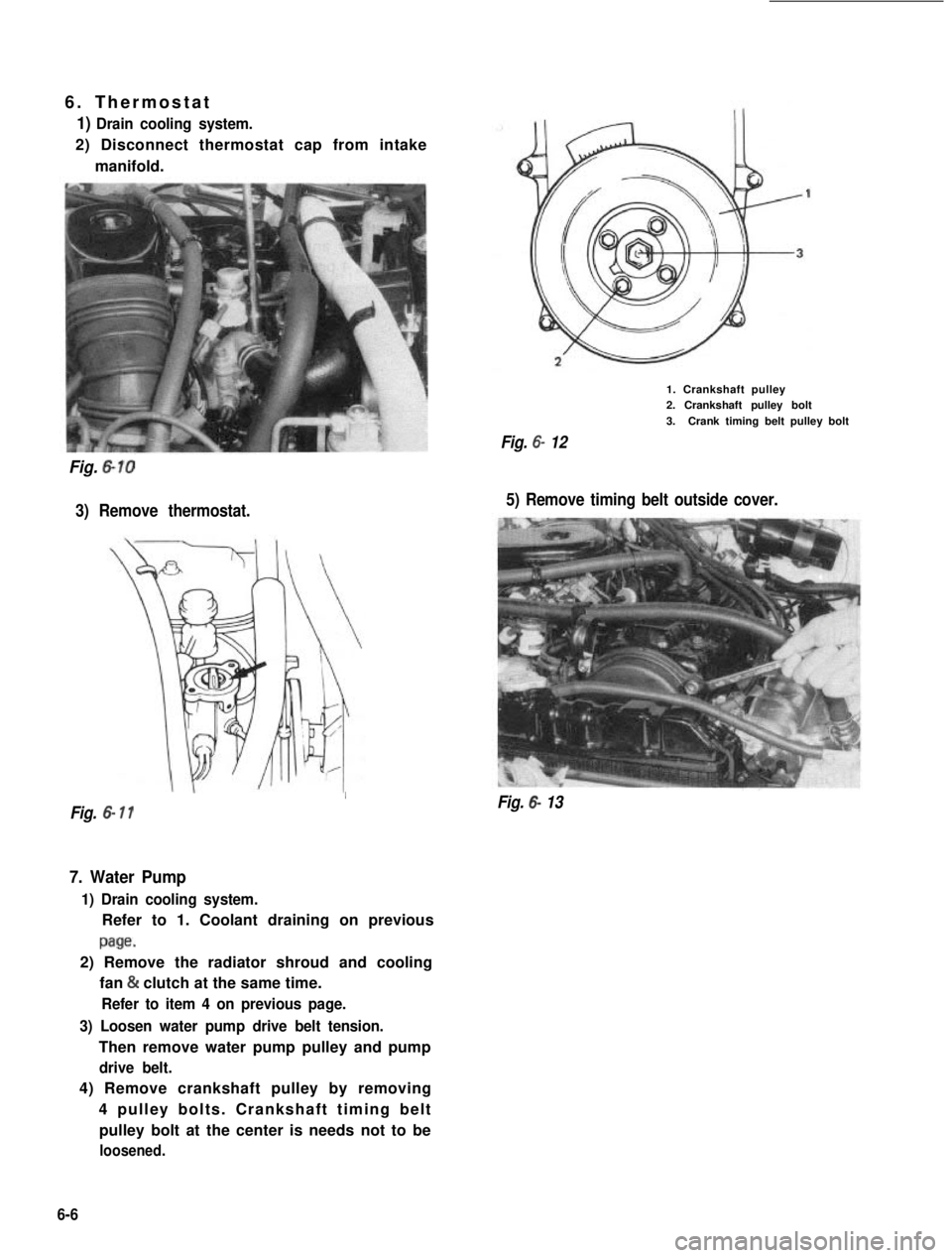
1) Drain cooling system.
2) Disconnect thermostat cap from intake
manifold.
Fig. 6-10
3) Remove thermostat.
1. Crankshaft pulley2. Crankshaft pulley bolt
3.Crank timing belt pulley bolt
Fig. 6- 12
5) Remove timing belt outside cover.
I
Fig. 6- 11Fig. 6- 13
7. Water Pump
1) Drain cooling system.
Refer to 1. Coolant draining on previous
page.
2) Remove the radiator shroud and cooling
fan & clutch at the same time.
Refer to item 4 on previous page.
3) Loosen water pump drive belt tension.
Then remove water pump pulley and pump
drive belt.
4) Remove crankshaft pulley by removing
4 pulley bolts. Crankshaft timing belt
pulley bolt at the center is needs not to be
loosened.
6-6