brake fluid SUZUKI GRAND VITARA 1987 Service Repair Manual
[x] Cancel search | Manufacturer: SUZUKI, Model Year: 1987, Model line: GRAND VITARA, Model: SUZUKI GRAND VITARA 1987Pages: 962, PDF Size: 27.87 MB
Page 33 of 962

1-3. CHASSIS AND BODY
30. CLUTCH PEDAL INSPECTION
1) Check clutch pedal height. It should be the
same as brake pedal height.
2) Check clutch pedal free travel.
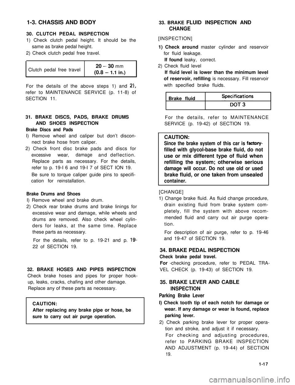
Clutch pedal free travel20 - 30 mm
(0.8 - 1.1 in.)
For the details of the above steps 1) and 2),
refer to MAINTENANCE SERVICE (p. 11-8) of
SECTION 11.
31. BRAKE DISCS, PADS, BRAKE DRUMS
AND SHOES INSPECTION
Brake Discs and Pads
I) Remove wheel and caliper but don’t discon-
nect brake hose from caliper.
2) Check front disc brake pads and discs for
excessivewear,damageand deflection.
Replace parts as necessary. For the details,
refer to p. 19-I 6 and 19-I 7 of SECT ION 19.
Be sure to torque caliper guide pins to specifi-
cation for reinstallation.
Brake Drums and Shoes
I) Remove wheel and brake drum.
2) Check rear brake drums and brake linings for
excessive wear and damage, while wheels and
drums are removed. Also check wheel cylin-
ders for leaks, at the same time. Replace
these parts as necessary.
For the details, refer to p. 19-21 and p. 19-
22 of SECTION 19.
32. BRAKE HOSES AND PIPES INSPECTION
Check brake hoses and pipes for proper hook-
up, leaks, cracks, chafing and other damage.
Replace any of these parts as necessary.
CAUTION:
After replacing any brake pipe or hose, be
sure to carry out air purge operation.
33. BRAKE FLUID INSPECTION AND
CHANGE
[INSPECTION]
1) Check around master cylinder and reservoir
for fluid leakage.
If found leaky, correct.
2) Check fluid level
If fluid level is lower than the minimum level
of reservoir, refilling is necessary. Fill reservoir
with specified brake fluids.
Brake fluid Speifi;t3ons
For the details, refer to MAINTENANCE
SERVICE (p. 19-42) of SECTION 19.
CAUTION:
Since the brake system of this car is factory-
filled with glycol-base brake fluid, do not
use or mix different type of fluid when
refilling the system; otherwise serious
damage will occur. Do not use old or used
brake fluid, or one taken from unsealed
container.
[CHANGE]
1) Change brake fluid. As fluid change procedure,
drain existing fluid from brake system com-
pletely, fill the system with above recom-
mended fluid and carry out air purge opera-
tion.
For description of air purge, refer to p. 19-46
and 19-47 of SECTION 19.
34. BRAKE PEDAL INSPECTION
Check brake pedal travel.
For -checking procedure, refer to PEDAL TRA-
VEL CHECK (p. 19-43) of SECTION 19.
35. BRAKE LEVER AND CABLE
INSPECTION
Parking Brake Lever
I) Check tooth tip of each notch for damage or
wear. If any damage or wear is found, replace
parking lever.
2) Check parking brake lever for proper opera-
tion and stroke, and adjust it if necessary.
For checking and adjusting procedures,
refer to PARKING BRAKE INSPECTION
AND ADJUSTMENT (p. 19-44) of SECTION
19.
1-17
Page 51 of 962

Condition
Excessive pedal travel
(Pedal stroke too
large)
Possible cause
1. Partial brake system failure
2. Insufficient fluid in master
cylinder reservoirs
Correction
Check diagonal brake systems and
repair as necessary
Fill reservoirs with approved brake
fluid. Check for leaks and air in
brake systems. Check warning light.
Bleed system if necessary.
3. Air in system (Pedal soft/spongy)Bleed system
4. Rear brake system not adjustedAdjust rear brakes (Repair auto
(malfunctioning auto adjustingadjusting mechanism)
mechanism)
5. Bent brake shoesReplace brake shoes
6. Worn rear brake shoesReplace brake shoes.
Dragging brakes (A
very light drag is pre-
sent in all disc brakes
immediately after
pedal is released)
1. Master cylinder pistons not
returning correctly
2. Clogged return port in master
cylinder
3. Restricted brake tubes or hoses
4. Incorrect parking brake
adjustment
5. Weakened or broken return
springs in the brake
Repair master cylinder
Clean
Check for soft hoses or damaged tubes
and replace with new hoses and/or
new double-walled steel brake tubing
Check and adjust to correct specifica-
tions
Replace
6. Sluggish parking-brake cables or
linkage
Repair or replace
7. Wheel cylinder or caliper piston
sticking
Repair as necessary
Pedal pulsation1. Damaged or loose wheel bearingsReplace wheel bearings
(Pedal pulsates when2. Excessive disc lateral runout Check per instructions. If not within
depressed for braking)specifications, replace or machine the
disc.
3. Parallelism not within specifica-Check per instructions. If not within
tionsspecifications, replace or machine the
disc.
4. Rear drums out of roundCheck runout.
Braking noise1. Glazed shoe linings, or foreignRepair or replace shoe lining
matters stuck to linings
2. Worn or distorted shoe liningsReplace shoe lining (or pad)
3. Loose front wheel bearingsReplace wheel bearings
4. Distorted backing plates or looseReplace or retighten securing bolts
mounting bolts
2-13
Page 244 of 962
![SUZUKI GRAND VITARA 1987 Service Repair Manual [Carrier and hold-down]
The battery carrier and hold-down clamp should
be clean and free from corrosion before instal-
ling the battery. The carrier should be in good
condition so that it will support SUZUKI GRAND VITARA 1987 Service Repair Manual [Carrier and hold-down]
The battery carrier and hold-down clamp should
be clean and free from corrosion before instal-
ling the battery. The carrier should be in good
condition so that it will support](/img/20/57437/w960_57437-243.png)
[Carrier and hold-down]
The battery carrier and hold-down clamp should
be clean and free from corrosion before instal-
ling the battery. The carrier should be in good
condition so that it will support the battery
securely and keep it level.
Make certain there are no parts in carrier before
installing the battery.
To prevent the battery from shaking in its
carrier, the hold-down bolts should be tight but
not over tightened.
[Visual inspection]
Check for obvious damage, such as cracked or
broken case or cover, that could permit loss of
electrolyte. If obvious damage is noted, replace
the battery. Determine cause of damage and
correct as needed.
Check the battery terminal and cords for corro-
sion. If any, it should be cleaned.
[Built-in indicator]
This sealed battery has a built-in temperature
compensated indicator in the top of the battery.
This indicator is to be used with the following
diagnostic procedure. When observing the
indicator, make sure that the battery has a clean
top. A light may be needed in some poorly-lit
areas.
Under normal operation, two indications can
be seen
2
Clear
RedCHARGING
NECESSARY
Fig. lo-23
l Clear with Red Dot
This means the discharging battery. In this case,
charge the battery until the indicator will be
blue with red dot. The charging and electrical
systems should also be checked at this time. If
any defective is found, correct it. While charging
it, if the battery feels hot 52°C (125” F), or if
violent gassing or spewing of electrolyte through
the vent hole occurs, discontinue charging or
reduce charging rate.
[Jump starting in case of emergency with
auxiliary (booster) battery]
NOTE:
l Do not push or tow the vehicle to start.
Damage to the emission system and/or to
other parts of the vehicle may result.
8 Both booster and discharged battery should
be treated carefully when using jumper cables.
Follow the procedure outlined below, being
careful not to cause sparks:
CAUTION:
l Departure from these conditions or the
procedure below could result in: (1)
Serious personal injury (particularly to
eyes) or property damage from such
causes as battery explosion, battery acid,
or electrical burns; and/or (2) damage to
electronic components of either vehicle.
l Never expose battery to open flame or
electric spark-batteries generate a gas
which is flammable and explosive.
l Remove rings,watches,and other
jewelry. Wear approved eye protection.
l Do not allow battery fluid to contact
eyes, skin, fabrics, or painted surfaces -
fluid is a corrosive acid. Flush any con-
tacted area with water immediately and
thoroughly. Be careful that metal tools
or jumper cables do not contact the
positive battery terminal (or metal in
contact with it) and any other metal on
the car, because a short circuit could
occur. Batteries should always be kept
out of the reach of children.
1) Set parking brake and place transmission in
neutral. Turn off the ignition, turn off lights
and all other electrical loads.
2) Check electrolyte level. If level is below low
level line, replace battery.
NOTE:
When jump starting an engine with charging
equipment, be sure equipment used is 12volt
and negative ground. Do not use 24volt charging
equipment. Using each equipment can cause
serious damage to the electrical system or
electronic parts.
10-11
Page 323 of 962

Fig. 16-19-1 @ Special tool (Brake drum remover
09943-355 7 1)
Fig. 16-10 @ Special tool (Rear axle remover
09922-66010)
@ Special tool (Sliding hammer@ Special tool (Sliding hammer
09942- 15510)09942-15510)
Disconnect brake pipe from wheel cylinder.
Have a small plug ready for use when disconnect-
ing pipe. As pipe comes off the wheel cylinder,
plug the pipe to prevent brake fluid from
leaking out.
And remove 4 brake backing plate securing
bolts.
Fig. 16-9-2 @ Plug
Using special tools indicated below, draw out
each axle shaft with brake backing plate.
Disconnect propeller shaft as in the case of front
axle, and detach and take down differential
carrier case from housing by removing 8 bolts.
Fig. 16-11
16-5
Page 350 of 962

REMOVALRear Axle Shaft
Shock Absorber
The shock absorber is non-adjustable, non-
refillable, and cannot be disassembled. The only
service the shock absorber requires is replace-
ment when it has lost its resistance, is damaged,
or leaking oil or gas.
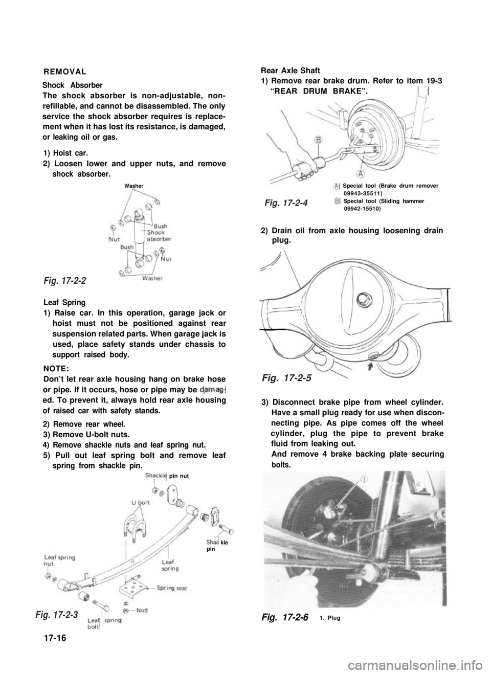
1) Remove rear brake drum. Refer to item 19-3
“REAR DRUM BRAKE”.I /
1) Hoist car.
2) Loosen lower and upper nuts, and remove
shock absorber.
Washer@ Special tool (Brake drum remover09943-35511)
Leaf Spring
1) Raise car. In this operation, garage jack or
hoist must not be positioned against rear
suspension related parts. When garage jack is
used, place safety stands under chassis to
support raised body.
NOTE:
Don’t let rear axle housing hang on brake hose
or pipe. If it occurs, hose or pipe may be d,amag-
ed. To prevent it, always hold rear axle housing
of raised car with safety stands.
2) Remove rear wheel.
3) Remove U-bolt nuts.
4) Remove shackle nuts and leaf spring nut.
5) Pull out leaf spring bolt and remove leaf
spring from shackle pin.
ShTckle pin nut
Sha’, klepin
@Special tool (Sliding hammer09942-15510)
2) Drain oil from axle housing loosening drain
plug.
3) Disconnect brake pipe from wheel cylinder.
Have a small plug ready for use when discon-
necting pipe. As pipe comes off the wheel
cylinder, plug the pipe to prevent brake
fluid from leaking out.
And remove 4 brake backing plate securing
bolts.
*Nut
;-; wring
17-16
Fig. 17-2-61. Plug
Fig. 17-2-2
Fig. 17-2-3
Fig. 17-2-4
Fig. 17-2-5
Page 389 of 962
![SUZUKI GRAND VITARA 1987 Service Repair Manual MASTER CYLINDER ASSEMBLY
[GENERAL DESCRIPTION]
The master cylinder has two pistons and three piston cups. Its hydraulic pressure is produced in the
primary (“a” in the below figure) and secondary SUZUKI GRAND VITARA 1987 Service Repair Manual MASTER CYLINDER ASSEMBLY
[GENERAL DESCRIPTION]
The master cylinder has two pistons and three piston cups. Its hydraulic pressure is produced in the
primary (“a” in the below figure) and secondary](/img/20/57437/w960_57437-388.png)
MASTER CYLINDER ASSEMBLY
[GENERAL DESCRIPTION]
The master cylinder has two pistons and three piston cups. Its hydraulic pressure is produced in the
primary (“a” in the below figure) and secondary (“b”) chambers. The hydraulic pressure produced in the
primary chamber (“a”) acts on the front wheel brakes (right & left).
Also, the hydraulic pressure produced in the secondary chamber (“b”) acts on the rear wheel brakes
(right & left).
NOTE:
Replace all components included in repair kits to service this master cylinder. Lubricate rubber parts with
clean, fresh brake fluid to ease assembly. Do not use lubricated shop air on brake parts as damage to rubber
components may result. If any hydraulic component is removed or brake line disconnected, bleed the
brake system. The torque values specified are for dry, unlubricated fasteners.
1.Piston stopper circllp
2.Piston stopper
3.Piston stopper sealing
4.Primary piston
5.Piston cup
6.Secondary piston pressure cup
7.Piston cup
8Secondary piston
9.Return spring secondary seat
10.Secondary piston return spring
11.Secondary piston stopper bolt
12.Master cylinder body
A :Primary piston
BSecondary piston
Fig. 19-3
[Master cylinder OPERATION]
Normal operation
Depressing the brake pedal forces the primary piston“A” to move to the left in the below figure and
consequently the hydraulic pressure is produced in the chamber “a”.
By means of this pressure and the return spring force, the secondary piston “B” is also pushed to the left
and thus the hydraulic pressure is produced in the chamber “b”.
Fig. 19-3-1
19-4
Page 390 of 962

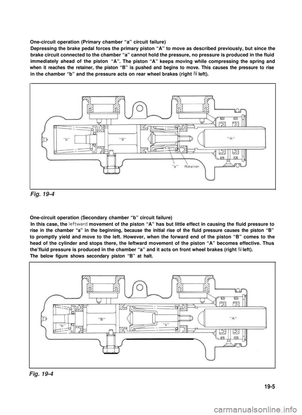
One-circuit operation (Primary chamber “a” circuit failure)
Depressing the brake pedal forces the primary piston “A” to move as described previously, but since the
brake circuit connected to the chamber “a” cannot hold the pressure, no pressure is produced in the fluid
immediately ahead of the piston“A”. The piston “A” keeps moving while compressing the spring and
when it reaches the retainer, the piston “B” is pushed and begins to move. This causes the pressure to rise
in the chamber “b” and the pressure acts on rear wheel brakes (right & left).
One-circuit operation (Secondary chamber “b” circuit failure)
In this case, the leftward movement of the piston “A” has but little effect in causing the fluid pressure to
rise in the chamber “a” in the beginning, because the initial rise of the fluid pressure causes the piston “B”
to promptly yield and move to the left. However, when the forward end of the piston “B” comes to the
head of the cylinder and stops there, the Ieftward movement of the piston “A” becomes effective. Thus
the’fluid pressure is produced in the chamber “a” and it acts on front wheel brakes (right & left).
The below figure shows secondary piston “B” at halt.
19-5
Fig. 19-4
Fig. 19-4
Page 392 of 962
![SUZUKI GRAND VITARA 1987 Service Repair Manual [Caliper OPERATION]
Single piston floating caliper type
The single piston floating caliper type brake is
employed in this model. One cylinder and one
piston are used for this type. (The cylinder is
co SUZUKI GRAND VITARA 1987 Service Repair Manual [Caliper OPERATION]
Single piston floating caliper type
The single piston floating caliper type brake is
employed in this model. One cylinder and one
piston are used for this type. (The cylinder is
co](/img/20/57437/w960_57437-391.png)
[Caliper OPERATION]
Single piston floating caliper type
The single piston floating caliper type brake is
employed in this model. One cylinder and one
piston are used for this type. (The cylinder is
constructed as a monoblock with the caliper.)
Fluid pressure generated in the cylinder causes
the pad (1) on the piston side to press against
the disc. At the same time, the floating type
caliper body is moved to the right by the cylin-
der pressure, as shown in below figure, which
pulls pad (2) against the disc and so brakes the
wheel.
Caliper body
\Brake disc (rotor)
Fig. 19-6 - ’
The disc brake has no servo assistance as in drum
braking, and it is necessary to increase the work-
ing pressure of the piston and pad. For this pur-
pose, the wheel cylinder has a large bore. Even
only a little change in clearance between the disc
and pad has therefore a large influence on the
brake pedal stroke. It is necessary to have the
clearance adjusted to the minimum at all times,
by means of the piston (rubber) seal.
Piston seal (Rubber seal)Piston sealWinder (Rubber seal)
II
IPiston
Hydraulic pressure
“OFF“
Fig. 19-7
Clearance correction
Piston
Hydraulic pressure
“ON”
When oil pressure is applied to the piston, the
piston moves forward. The rubber seal, which
exerts considerable pressure against the piston,
moves with the cylinder. However, as a part of
the rubber seal has been fixed into a groove in
the cylinder, the shape of the rubber seal is dis-
torted toward internal end of the cylinder, as
shown in above figure. When pressure is taken
off from the foot brake pedal and fluid pressure
is released from the piston, a restoring force is
generated at the seal and pushes the piston back.
As the pads wear away and the clearance be-
tween the disc and pads becomes larger, the
piston moves a larger distance. The seal then
could change in shape further but, since the end
of the seal is fixed into the groove in the cylin-
der, the distortion is limited to the same amount
as previously described. The piston moves
further to cover the distance of clearance. The
piston returns by the same distance and the
rubber seal recovers its shape as described
above and thus the clearance between the disc
and pads are maintained in adjustment.
19-7
Cylinder
Page 394 of 962
![SUZUKI GRAND VITARA 1987 Service Repair Manual [Rear brake OPERATION]
With the general drum brake type, when the
brake pedal is depressed, two pistons in the
wheel cylinder force the brake shoes outward,
restraining the turn of the drum.
The more SUZUKI GRAND VITARA 1987 Service Repair Manual [Rear brake OPERATION]
With the general drum brake type, when the
brake pedal is depressed, two pistons in the
wheel cylinder force the brake shoes outward,
restraining the turn of the drum.
The more](/img/20/57437/w960_57437-393.png)
[Rear brake OPERATION]
With the general drum brake type, when the
brake pedal is depressed, two pistons in the
wheel cylinder force the brake shoes outward,
restraining the turn of the drum.
The more the brake shoes get worn, the longer
distance the pistons must move. As a result, the
brake pedal travel (pedal-to-wall clearance)
increases. Then the shoe clearance must be
adjusted by the shoe adjusting screws. Thus
periodical adjustment is required for the drum
brake type in general.
This rear brake is provided with a self-adjusting
system which automatically adjusts the shoe-to-
drum clearance (pedal-to-wall clearance) caused
by such brake shoe wear.
Clearance correction
In each rear wheel cylinder, pistons, piston cups,
and a piston spring (1) are installed. When the
brake pedal is depressed, fluid pressure is applied
to the inside of the chamber on the piston (2),
(3).
Being actuated by this pressure, the piston (2)
moves to the left (piston (3) moves to the right)
in the following figure and presses the brake
shoe against the brake drum, thus producing
brake force.
(2)(3)
Fig. 19-9
At this time, the distance the brake shoe moves
is “B”,that is, the distance that “A” (the end of
the long hole made in the brake shoes web)
moves till it contacts the lever (1) which is fitted
in the long hole.
Fig. 19-10
When the brake pedal is depressed, the piston
and brake shoe move toward the brake drum
side by the aforementioned distance “B” and
“A” of the brake shoe web contacts the lever
(1). As the brake shoe gets worn and the brake
shoe clearance becomes larger, the force applied
to the lever (1) at the time of such a contact
becomes larger. When it exceeds 10 - 12 kg
(22 - 26 Ibs), the “A” of the brake shoe web
moves the lever (1) as much as the amount of
the brake shoe lining wear toward the direction
as shown with an arrow in the figure. Thus the
shoe is forced against the drum and the brake
force is produced.
19-9
Page 400 of 962

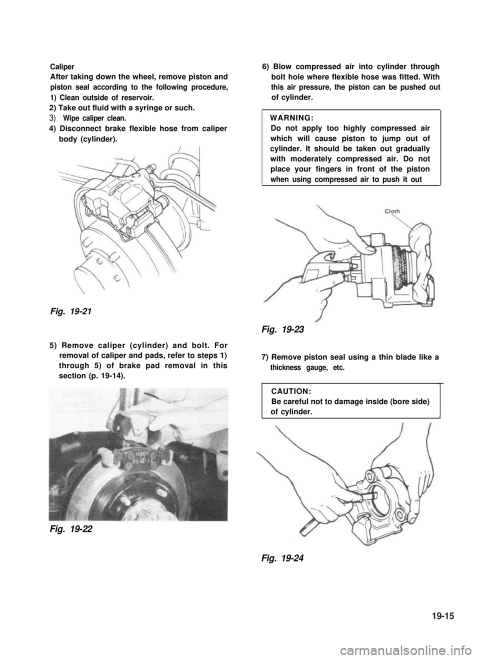
Caliper
After taking down the wheel, remove piston and
piston seal according to the following procedure,
1) Clean outside of reservoir.
2) Take out fluid with a syringe or such.
3)Wipe caliper clean.
4) Disconnect brake flexible hose from caliper
body (cylinder).
Fig. 19-21
6) Blow compressed air into cylinder through
bolt hole where flexible hose was fitted. With
this air pressure, the piston can be pushed out
of cylinder.
WARNING:
Do not apply too highly compressed air
which will cause piston to jump out of
cylinder. It should be taken out gradually
with moderately compressed air. Do not
place your fingers in front of the piston
when using compressed air to push it out
Fig. 19-23
5) Remove caliper (cylinder) and bolt. For
removal of caliper and pads, refer to steps 1)
through 5) of brake pad removal in this
section (p. 19-14).
Fig. 19-22
7) Remove piston seal using a thin blade like a
thickness gauge, etc.
CAUTION:
Be careful not to damage inside (bore side)
of cylinder.1
Fig. 19-24
19-15