brake sensor SUZUKI GRAND VITARA 1987 Service Repair Manual
[x] Cancel search | Manufacturer: SUZUKI, Model Year: 1987, Model line: GRAND VITARA, Model: SUZUKI GRAND VITARA 1987Pages: 962, PDF Size: 27.87 MB
Page 46 of 962

ConditionPossible causeCorrection
High fuel consumptionAbnormal condition ignition system
1. Improper ignition timingAdjust
2. Leak or loose connection of high tension cordRepair or replace
3. Defective spark plug (improper gap, heavyClean, adjust or replace
deposits, and burned electrodes, etc..)
4. Cracked distributor cap or rotorReplace
5. Malfunctioning mechanical and vacuumCheck and repair or
advancers in distributorreplace
Abnormal condition in fuel system
1. Improper float levelAdjust
2. Fuel leakage from tank, pipe or carburetorRepair or replace
3. Malfunctioning carburetor choke systemRepair or replace
4. Dirty or clogged carburetor jetsClean
5. Clogged air cleaner elementClean or replace
6. Malfunctioning thermostatically controlledCheck and repair or
air cleanerreplace
Abnormal condition in engine
1. Low compressionPreviously outlined
2. Poor valve seatingRepair or replace
3. Improper valve clearanceAdjust
Emission control
1. Air leaks at exhaust manifoldTighten manifold bolts
and nuts.
Replace gasket.
2. Oxygen sensor out of orderReplace.
3. Water temperature switch out of orderReplace.
4. Malfunctioning throttle position switchReplace
5. Malfunctioning MCS (mixture controlReplace
solenoid) valve in carburetor
6. Malfunctioning EGR valveReplace
Others
1. Dragging brakesRepair or replace
2. Slipping clutchAdjust or replace
3. Improper tire pressureAdjust
Excessive engine oilOil leakage
consumption1. Loose oil drain plugTighten
2. Loose oil pan securing boltsTighten
3. Deteriorated or broken oil pan sealantReplace sealant
4. Leaky oil sealsReplace
5. Blown cylinder head gasketReplace
6. Improper tightening of oil filterTighten
7. Loose oil pressure switchTighten
2-8
Page 450 of 962

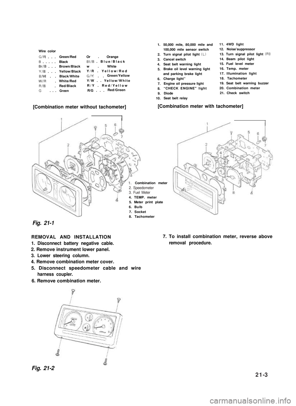
Wire color
G/R . . .Green/RedOr . Orange
0 . . . . .BlackBI/B . Blue/Black
0rlB . . .Brown/Blackw . White
Y/B . . .Yellow/BlackY/R . Yellow/Red
B/W . .Black/WhiteG/Y . .Green/Yellow
W/R .White/RedY/W . . Yellow/White
RIB .Red/BlackR/Y . Red/Yellow
G. . .GreenR/G . . .Red/Green
1.
2.
3.
4.
5.
6.7.
8.
9.
10.
50,000 mile, 80,000 mile and11. 4WD light
100,000 mile sensor switch12. Noise’suppressor
Turn signal pilot light (Lb13. Turn signal pilot light (RI
Cancel switch14. Beam pilot light
Seat belt warning light15. Fuel level meter
Brake oil level warning light16. Temp. meter
and parking brake light17. Illumination light
Charge light”18. Tachometer
Engine oil pressure light19. Seat belt warning buzzer
“CHECK ENGINE" light 20. Combination meter
Diode21. Check switch
Seat belt relay
[Combination meter without tachometer][Combination meter with tachometer]
4. TEMP. meter5. Meter print plate
6. Bulb
7. Socket
Combination meter
Fig. 21-1
8. Tachometer
REMOVAL AND INSTALLATION
1. Disconnect battery negative cable.
2. Remove instrument lower panel.
3. Lower steering column.
4. Remove combination meter cover.
5. Disconnect speedometer cable and wire
harness coupler.
7. To install combination meter, reverse above
removal procedure.
6. Remove combination meter.
Fig. 21-2
2. Speedometer3. Fuel Meter
21-3