ground clearance SUZUKI GRAND VITARA 1987 Service Repair Manual
[x] Cancel search | Manufacturer: SUZUKI, Model Year: 1987, Model line: GRAND VITARA, Model: SUZUKI GRAND VITARA 1987Pages: 962, PDF Size: 27.87 MB
Page 40 of 962

2-1. ENGINE
Cond it ion
Poor starting
(Hard starting)
Possible cause
Starter will not run
1. Main fuse blown off
2. Contact not closing in main switch, or this
switch open-circuited
3. Run-down battery
4. Defective magnetic switch of starter
5. Loose battery terminal connection
6. Defective brushes in starter
7. Loose battery cord connection
8. Open in field or armature circuit of starter.
Correction
Replace
Repair or replace
Recharge
Replace
Clean and retighten
Replace
Retighten
Repair or replace
No sparking
1. Defective spark plugAdjust gap, or replace
2. High tension cord short-circuited (grounded)Repair or replace
3. Cracked rotor or cap in distributorReplace
4. Defective signal generator or ignitorReplace
5. Maladjusted signal rotor air gap.Adjust
6. Contact not closing positively in main switch,Replace
or this switch open-circuited
7. Loose or blown fuseSet right or replace
8. Improper ignition timingAdjust
9. Defective ignition coil.Replace
Faulty intake and exhaust systems
1. Carburetor out of adjustment
2. Fuel pump not discharging adequately
3. Clogged fuel filter
4. Defective choke mechanism
5. Loose intake manifold
6. Dirty and clogged carburetor
7. Float level out of adjustment
8. Clogged fuel hose or pipe
9. Not enough fuel in the tank
10. Malfunctioning fuel cut solenoid valve
Adjust
Replace
Clean, or replace
Repair or replace
Retighten
Disassemble and clean
Adjust
Clean or replace
Refill
Check solenoid valve for
proper operation and
replace if necessary
Abnormal engine internal condition
1. Ruptured cylinder head gasket
2. Improper valve clearance
3. Weakened or broken valve spring
4. Loose manifold, permitting air to be
drawn in
5. Worn pistons, rings or cylinders
Replace
Adjust
Replace
Retighten and, as neces-
sary, replace gasket
Replace worn rings and
pistons and rebore as
necessary
2-2
Page 41 of 962

Condition
Poor starting
(Hard starting)
Possible cause
6. Broken valve timing belt
7. Poor valve seating
8. Wrong kind of engine oil
9. Burnt valves
10. Sticky valve stem
Correction
Replace
Repair or replace
Replace
Replace
Correct or replace valve
and guide
Emission control
1. Malfunctioning PCV valve
2. Loose connection or disconnection of
vacuum hoses
Replace.
Connect securely.
3. ECM is poorly grounded.Ground ECM securely
Not enough powerInadequate compression
1. Improper valve clearance
2. Valves not seating tight
3. Valve stems tending to seize
4. Broken or weakened valve spring
5. Piston rings seized in grooves, or broken
6. Worn pistons, rings or cylinders
Adjust
Repair
Replace
Replace
Replace
Replace worn parts and
rebore as necessary
7. Leaky cylinder head gasketReplace
Improperly timed ignition
1. Improper ignition timing
2. Defective spark plug
3. Worn distributor terminals
4. Leaks, loose connection or disconnection of
high tension cord
5. Malfunctioning ignition timing advancers
Adjust
Adjust gap or replace
Dress or replace
Connect or replace as
necessary
Replace
Fuel system out of order
1. Clogged carburetor jets
2. Defective fuel pump
3. Clogged fuel filter
4. Malfunctioning choke system
5. Float level out of adjustment
6. Clogged fuel pipe
7. Clogged fuel tank outlet
8. Loose joint in fuel system
Disassemble and clean
Repair or replace
Replace
Adjust or replace
Adjust
Clean or replace
Clean
Retighten
Abnormal condition in air intake system
1. Air cleaner dirty and clogged
2. Poor returning motion of choke valve
Clean or replace
Repair, adjust or replace
Overheating tendency of engine
1. (Refer to the section entitled “over-
heating.“)
2-3
Page 90 of 962

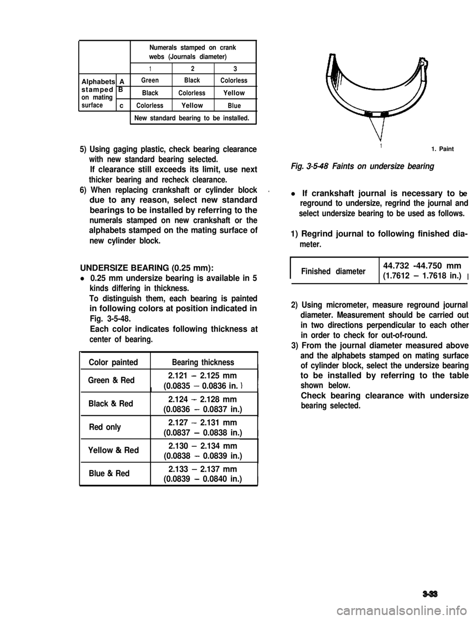
Numerals stamped on crank
webs (Journals diameter)
123
Alphabets AGreenBlackColorless
stamped Bon matingBlackColorlessYellow
surfacecColorlessYellowBlue
New standard bearing to be installed.
5) Using gaging plastic, check bearing clearance
with new standard bearing selected.
If clearance still exceeds its limit, use next
thicker bearing and recheck clearance.
6) When replacing crankshaft or cylinder block.
due to any reason, select new standard
bearings to be installed by referring to the
numerals stamped on new crankshaft or the
alphabets stamped on the mating surface of
new cylinder block.
UNDERSIZE BEARING (0.25 mm):
l 0.25 mm undersize bearing is available in 5
kinds differing in thickness.
To distinguish them, each bearing is painted
in following colors at position indicated in
Fig. 3-5-48.
Each color indicates following thickness at
center of bearing.
Color paintedBearing thicknessI
Green & Red2.121 - 2.125 mm
(0.0835 - 0.0836 in. )III
Black & Red2.124 - 2.128 mm
(0.0836 - 0.0837 in.)
Red only2.127 - 2.131 mm
(0.0837 - 0.0838 in.)I
Yellow & Red2.130 - 2.134 mm
(0.0838 - 0.0839 in.)
Blue & Red2.133 - 2.137 mm
(0.0839 - 0.0840 in.)I
11. Paint
Fig. 3-5-48 Faints on undersize bearing
l If crankshaft journal is necessary to be
reground to undersize, regrind the journal and
select undersize bearing to be used as follows.
1) Regrind journal to following finished dia-
meter.
IFinished diameter44.732 -44.750 mm
(1.7612 - 1.7618 in.)I
2) Using micrometer, measure reground journal
diameter. Measurement should be carried out
in two directions perpendicular to each other
in order to check for out-of-round.
3) From the journal diameter measured above
and the alphabets stamped on mating surface
of cylinder block, select the undersize bearing
to be installed by referring to the table
shown below.
Check bearing clearance with undersize
bearing selected.
3-33
Page 382 of 962

Steering Gear Box
Check steering gear box for evidence of oil
leakage. If leakage is found, repair or replace
and then refill specified oil to specified level.
Refer to“18-5 INSPECTION OF COMPO-
NENT” in this section for steering gear box oil.
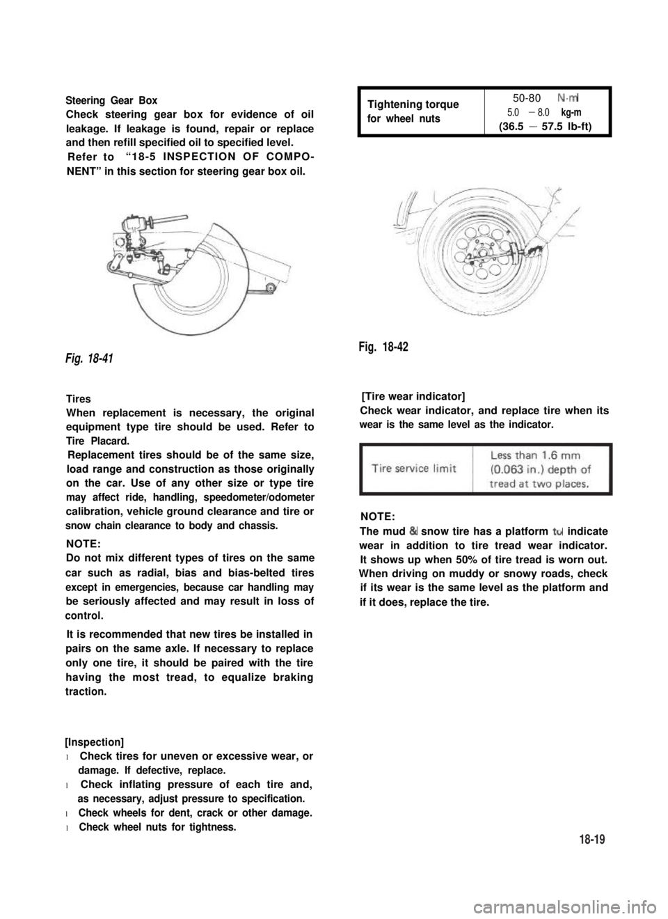
Tightening torque
for wheel nuts
50-80 N.m
5.0 - 8.0 kg-m
(36.5 - 57.5 lb-ft)
Fig. 18-42
Fig. 18-41
Tires[Tire wear indicator]
When replacement is necessary, the original
equipment type tire should be used. Refer to
Tire Placard.
Check wear indicator, and replace tire when its
wear is the same level as the indicator.
Replacement tires should be of the same size,
load range and construction as those originally
on the car. Use of any other size or type tire
may affect ride, handling, speedometer/odometer
calibration, vehicle ground clearance and tire or
snow chain clearance to body and chassis.
NOTE:
NOTE:
Do not mix different types of tires on the same
car such as radial, bias and bias-belted tires
except in emergencies, because car handling may
be seriously affected and may result in loss of
control.
The mud & snow tire has a platform ttr indicate
wear in addition to tire tread wear indicator.
It shows up when 50% of tire tread is worn out.
When driving on muddy or snowy roads, check
if its wear is the same level as the platform and
if it does, replace the tire.
It is recommended that new tires be installed in
pairs on the same axle. If necessary to replace
only one tire, it should be paired with the tire
having the most tread, to equalize braking
traction.
[Inspection]
l Check tires for uneven or excessive wear, or
damage. If defective, replace.
l Check inflating pressure of each tire and,
as necessary, adjust pressure to specification.
l Check wheels for dent, crack or other damage.
l Check wheel nuts for tightness.
18-19
Page 383 of 962
![SUZUKI GRAND VITARA 1987 Service Repair Manual Fig. 18-43 @ Tire tread wear indicator
@ Wear indicating platform
[ Inflation of tires]
l Tire inflation pressures are listed on the
Tire Placard at driver’s side of instrument
panel.
l Tire inflati SUZUKI GRAND VITARA 1987 Service Repair Manual Fig. 18-43 @ Tire tread wear indicator
@ Wear indicating platform
[ Inflation of tires]
l Tire inflation pressures are listed on the
Tire Placard at driver’s side of instrument
panel.
l Tire inflati](/img/20/57437/w960_57437-382.png)
Fig. 18-43 @ Tire tread wear indicator
@ Wear indicating platform
[ Inflation of tires]
l Tire inflation pressures are listed on the
Tire Placard at driver’s side of instrument
panel.
l Tire inflation pressures should be checked
(including spare tire) at least monthly and
when significantly changing the load in the
car.
l Always check tire inflation pressures when
tires are “cold”.
l Always use tire pressure gauge when checking
inflation pressure.
l Be sure to reinstall tire inflation valve caps to
prevent dirt and moisture from getting into
valve core, as they may cause air leakage.
l If air loss occurs while driving, do not drive
on the deflated tire more than is needed to
stop safety. Driving even a short distance on a
deflated tire can damage a tire and wheel
beyond repair.
NOTE:
Before installing wheels, remove any build-up of
corrosion on the wheel mounting surface and
brake drum or disc mounting surface by scraping
and wire brushing. Installing wheels without
good metal-to-metal contact at the mounting
surfaces can cause wheel nuts to loosen, which
can later allow a wheel to come off while the
car is moving.
RADIAL TIRES
.i II
9T
\
I
4-wheels
Fig. 18-44
fT
u
[I
5-wheels
[Wheels]
Wheels must be replaced if they are bent, dented,
have excessive lateral or radial runout, leak air
through welds, have elongated bolt holes, if
lug nuts won’t stay tight, or if they are heavily
rusted. Wheels with greater runout than shown
in below figure may cause objectional vibrations.
Replacement wheels must be equivalent to the
original equipment wheels in load capacity,
diameter,rim width, offset and mounting
configuration. A wheel of improper size or type
may affect wheel and bearing life, brake cooling,
speedometer/odometer calibration, car ground
clearance and tire clearance to the body and
chassis.
[Tire rotation]
“Rotate” tires at the regular intervals in order to
equalize tire wear and thereby make full use of
each tire. Refer to below figure for the scheme
of rotation. Adherence to this scheme prolongs
tire life.
18-20
Page 405 of 962

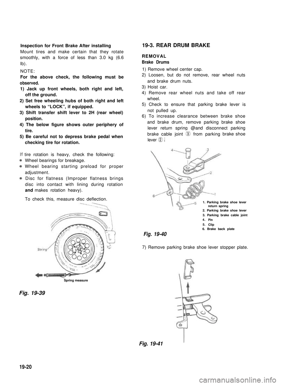
Inspection for Front Brake After installing
Mount tires and make certain that they rotate
smoothly, with a force of less than 3.0 kg (6.6
lb).
NOTE:
For the above check, the following must be
observed.
1) Jack up front wheels, both right and left,
off the ground.
2) Set free wheeling hubs of both right and left
wheels to “LOCK”, if equipped.
3) Shift transfer shift lever to 2H (rear wheel)
position.
4) The below figure shows outer periphery of
tire.
5) Be careful not to depress brake pedal when
checking tire for rotation.
tire rotation is heavy, check the following:
Wheel bearings for breakage.
Wheel bearing starting preload for proper
adjustment.
Disc for flatness (Improper flatness brings
disc into contact with lining during rotation
and makes rotation heavy).
To check this, measure disc deflection.
Spring measure
19-3. REAR DRUM BRAKE
REMOVAL
Brake Drums
1) Remove wheel center cap.
2) Loosen, but do not remove, rear wheel nuts
and brake drum nuts.
3) Hoist car.
4) Remove rear wheel nuts and take off rear
wheel.
5) Check to ensure that parking brake lever is
not pulled up.
6) To increase clearance between brake shoe
and brake drum, remove parking brake shoe
lever return spring @and disconnect parking
brake cable joint 0 from parking
lever 0.
brake shoe
1. Parking brake shoe leverreturn spring2. Parking brake shoe lever
3. Parking brake cable joint
4.Pin
5.Clip6. Brake back plate
Fig.19-40
7) Remove parking brake shoe lever stopper plate.
Fig. 19-39
Fig. 19-41
19-20