radio SUZUKI GRAND VITARA 1987 Service Repair Manual
[x] Cancel search | Manufacturer: SUZUKI, Model Year: 1987, Model line: GRAND VITARA, Model: SUZUKI GRAND VITARA 1987Pages: 962, PDF Size: 27.87 MB
Page 208 of 962
![SUZUKI GRAND VITARA 1987 Service Repair Manual 7-4. REMOVAL AND INSTALLATION
Removal
[Heater and blower motor]
1. Disconnect battery negative cable.
2. Drain cooling system.
WARNING:
To help avoid the danger of being burned, do
not remove the drai SUZUKI GRAND VITARA 1987 Service Repair Manual 7-4. REMOVAL AND INSTALLATION
Removal
[Heater and blower motor]
1. Disconnect battery negative cable.
2. Drain cooling system.
WARNING:
To help avoid the danger of being burned, do
not remove the drai](/img/20/57437/w960_57437-207.png)
7-4. REMOVAL AND INSTALLATION
Removal
[Heater and blower motor]
1. Disconnect battery negative cable.
2. Drain cooling system.
WARNING:
To help avoid the danger of being burned, do
not remove the drain plug and the radiator
cap while the engine and radiator are still hot.
Scalding fluid and steam can be blown out
under pressure if the plug and cap are taken
off too soon.
Fig 7-51. Drain plug2. Radiator
3. Disconnect heater inlet and outlet hoses
from heater unit pipes.
4. Remove instrument panel ass’y with speedo-
meter ass’y as follows.
1) Take off horn pad and remove steering
wheel using special tool @.
2) If equipped with radio and cigarette lighter,
disconnect radio and cigarette lighter lead
wires, and pull out radio case with radio
and cigarette lighter after loosening case
stay screw, and remove radio case bracket.
3) Pull out ashtray and loosen ashtray plate
screws.
4) Disconnect front food opening cable from
lock ass’y.
5) Loosen panel box stay screw and hood
opening cable lock nut on back side of
panel box cover.
6) Disconnect lead wires to control lever at
the coupler and heater control cables.
7) Pull out lever knobs and plate, and loosen
lever case screws.
8) Remove defroster and side ventilator hoses.
9) Disconnect lead wires to speedometer and
switches installed instrument panel at the
couplers.
10) Disconnect speedometer cable from speedo-
meter.
11) Release wire harness clamps installed to
instrument panel.
12) Loosen screws securing instrument panel.
13) Remove instrument panel.
NOTE:
l Before removing, recheck to ascertain all
hoses, wire harness, cables and screws are
disconnected from instrument paneL
l When removing heater lever case which is
fitted in steering column holder, be very
careful not to damage it
5. Remove steering column holder after loosen-
ing front door open stopper screws.
Fig. 7-7Fig. 7-6@ Special tool (Steering wheel
remover 09944-360 10)
7-5
Page 236 of 962

The alternator features a solid state regulator
that is mounted inside the alternator. All regula-
tor components are enclosed into a solid mold,
and this unit along with the brush holder assemb-
ly is attached to the slip ring end frame. The
regulator voltage setting cannot be adjusted.
The alternator rotor bearings contain enough
grease to eliminate the need for periodic lubri-
cation. Two brushes carry current through the
two slip rings to the field coil mounted on the
rotor, and under normal conditions will provide
long period of attention-free service.
The stator windings are assembled on the inside
of a laminated core that forms part of the
alternator frame. A rectifier bridge connected
to the stator windings contains six diodes,
and electrically changes the stator A.C. voltages
to a D.C. voltage which appears at the generator
output terminal.
The neutral diodes serve to convert the voltage
fluctuation at the neutral point to direct current
for increasing the alternator output.
A condenser mounted in the end frame protects
the diodes from high voltages and suppresses
radio noise.
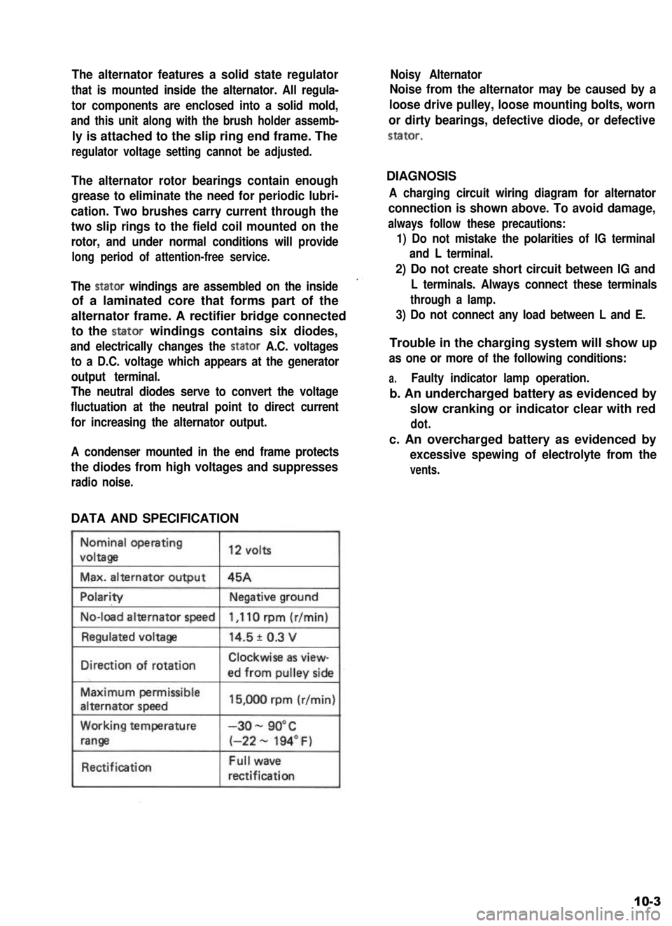
DATA AND SPECIFICATION
Nominal operating
voltaga
Max. alternator output
12 volts
45A
No-load alternator speed
IDirection of rotationClockwise as view-
ed from oullev side
Maximum permissible
alternator speed
Working temperature
range
Rectification
15,000 rpm (r/min)
-3o- 90°C
(-22 - 194” F)
Full wave
rectification
Noisy Alternator
Noise from the alternator may be caused by a
loose drive pulley, loose mounting bolts, worn
or dirty bearings, defective diode, or defective
stator.
DIAGNOSIS
A charging circuit wiring diagram for alternator
connection is shown above. To avoid damage,
always follow these precautions:
1) Do not mistake the polarities of IG terminal
and L terminal.
2) Do not create short circuit between IG and
L terminals. Always connect these terminals
through a lamp.
3) Do not connect any load between L and E.
Trouble in the charging system will show up
as one or more of the following conditions:
a.Faulty indicator lamp operation.
b. An undercharged battery as evidenced by
slow cranking or indicator clear with red
dot.
c. An overcharged battery as evidenced by
excessive spewing of electrolyte from the
vents.
10-3
Page 465 of 962

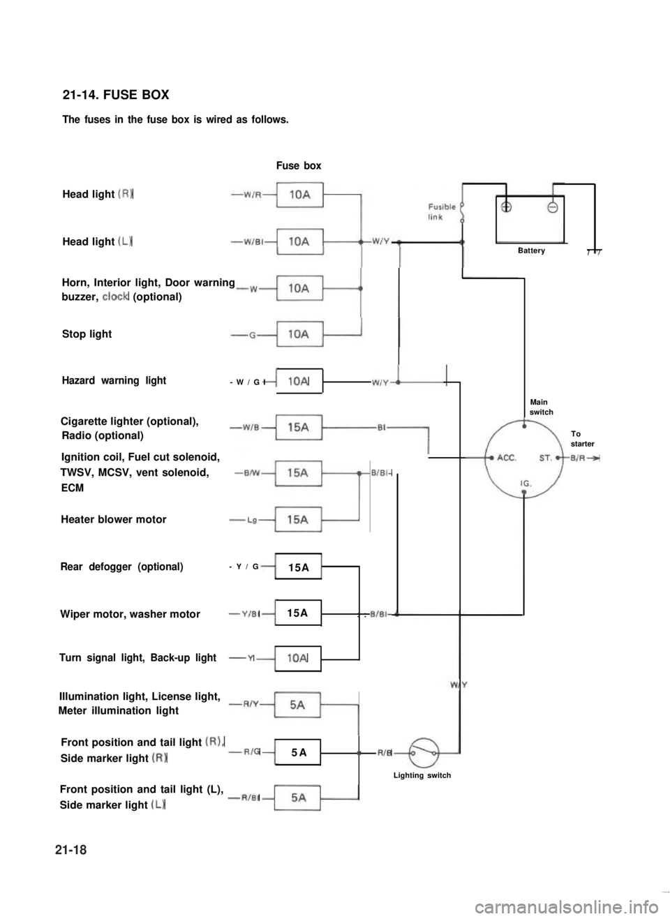
21-14. FUSE BOX
The fuses in the fuse box is wired as follows.
Head light (R)
Fuse box
Head light (L)Battery7
Horn, Interior light, Door warning
buzzer, ctock (optional)
Stop light
Hazard warning light-W/GI10AW,YI
Cigarette lighter (optional),
Radio (optional)
-w’B++-B7Ignition coil, Fuel cut solenoid,
TWSV, MCSV, vent solenoid,-B/W15A
3
BIBI-
ECM
Heater blower motor-L9
Rear defogger (optional)-Y/G15A
Wiper motor, washer motor-Y/El15A:: BIBI-
Turn signal light, Back-up light-Y10A
Illumination light, License light,
Meter illumination light
-R’y++lFront position and tail light (RI,
Side marker light (RI--RIG5A:: RIB
Lighting switch
Front position and tail light (L), --R,a,
Side marker light (L)
-t
-c
Mainswitch
Tostarter
B/R--,
-
21-18
Page 468 of 962

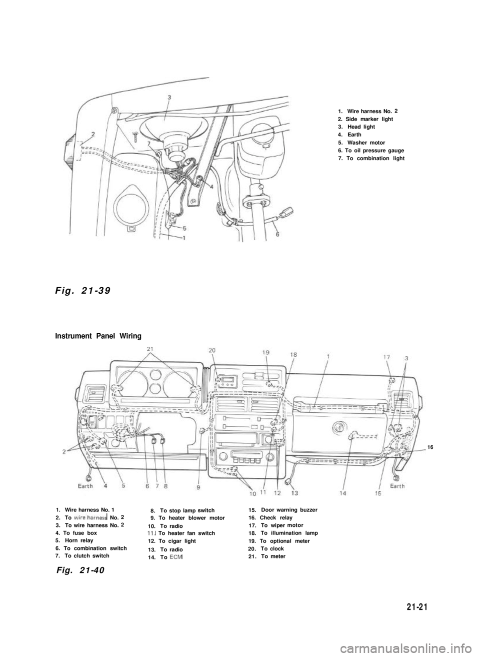
Fig. 21-39
Instrument Panel Wiring
1.Wire harness No.2
2. Side marker light3.Head light
4.Earth
5.Washer motor
6. To oil pressure gauge
7. To combination light
16
1.Wire harness No. 1
2.To wire~harness No.2
3.To wire harness No.2
4. To fuse box5.Horn relay
6. To combination switch7.To clutch switch
8.Tostop lampswitch15.Doorwarning buzzer
9. To heater blower motor16. Check relay
10.Toradio17.To wipermotor
Il. To heater fan switch18.To illumination lamp
12. To cigar light19. To optional meter
13.Toradio20.Toclock
14.ToECM21.Tometer
Fig. 21-40
21-21