door lock SUZUKI GRAND VITARA 1987 Service Repair Manual
[x] Cancel search | Manufacturer: SUZUKI, Model Year: 1987, Model line: GRAND VITARA, Model: SUZUKI GRAND VITARA 1987Pages: 962, PDF Size: 27.87 MB
Page 208 of 962
![SUZUKI GRAND VITARA 1987 Service Repair Manual 7-4. REMOVAL AND INSTALLATION
Removal
[Heater and blower motor]
1. Disconnect battery negative cable.
2. Drain cooling system.
WARNING:
To help avoid the danger of being burned, do
not remove the drai SUZUKI GRAND VITARA 1987 Service Repair Manual 7-4. REMOVAL AND INSTALLATION
Removal
[Heater and blower motor]
1. Disconnect battery negative cable.
2. Drain cooling system.
WARNING:
To help avoid the danger of being burned, do
not remove the drai](/img/20/57437/w960_57437-207.png)
7-4. REMOVAL AND INSTALLATION
Removal
[Heater and blower motor]
1. Disconnect battery negative cable.
2. Drain cooling system.
WARNING:
To help avoid the danger of being burned, do
not remove the drain plug and the radiator
cap while the engine and radiator are still hot.
Scalding fluid and steam can be blown out
under pressure if the plug and cap are taken
off too soon.
Fig 7-51. Drain plug2. Radiator
3. Disconnect heater inlet and outlet hoses
from heater unit pipes.
4. Remove instrument panel ass’y with speedo-
meter ass’y as follows.
1) Take off horn pad and remove steering
wheel using special tool @.
2) If equipped with radio and cigarette lighter,
disconnect radio and cigarette lighter lead
wires, and pull out radio case with radio
and cigarette lighter after loosening case
stay screw, and remove radio case bracket.
3) Pull out ashtray and loosen ashtray plate
screws.
4) Disconnect front food opening cable from
lock ass’y.
5) Loosen panel box stay screw and hood
opening cable lock nut on back side of
panel box cover.
6) Disconnect lead wires to control lever at
the coupler and heater control cables.
7) Pull out lever knobs and plate, and loosen
lever case screws.
8) Remove defroster and side ventilator hoses.
9) Disconnect lead wires to speedometer and
switches installed instrument panel at the
couplers.
10) Disconnect speedometer cable from speedo-
meter.
11) Release wire harness clamps installed to
instrument panel.
12) Loosen screws securing instrument panel.
13) Remove instrument panel.
NOTE:
l Before removing, recheck to ascertain all
hoses, wire harness, cables and screws are
disconnected from instrument paneL
l When removing heater lever case which is
fitted in steering column holder, be very
careful not to damage it
5. Remove steering column holder after loosen-
ing front door open stopper screws.
Fig. 7-7Fig. 7-6@ Special tool (Steering wheel
remover 09944-360 10)
7-5
Page 436 of 962
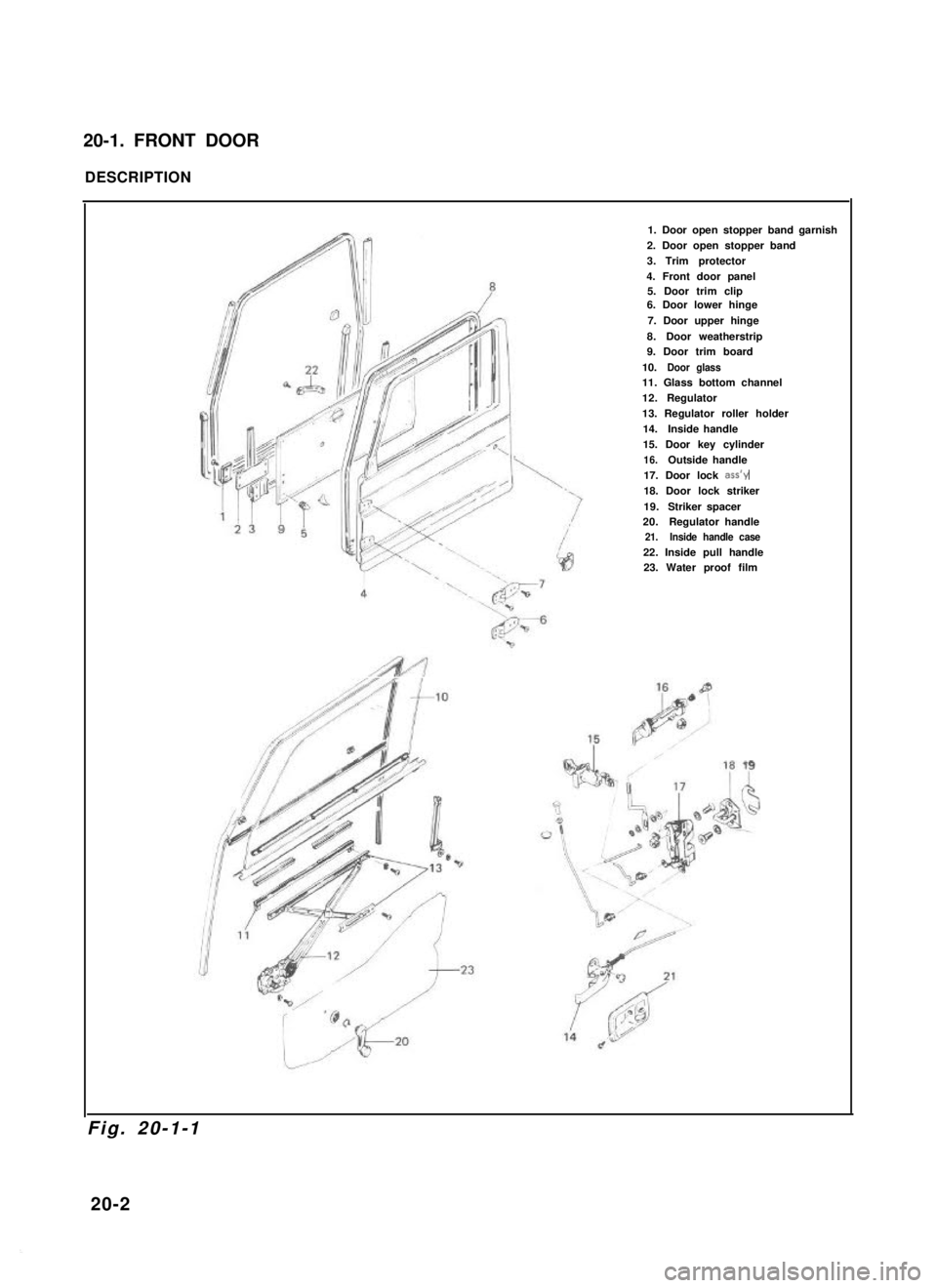
20-1. FRONT DOOR
DESCRIPTION
1. Door open stopper band garnish
2. Door open stopper band
3.Trim protector
4. Front door panel5. Door trim clip6. Door lower hinge
7. Door upper hinge
8.Door weatherstrip9. Door trim board
10.Door glass11. Glass bottom channel
12.Regulator
13. Regulator roller holder
14.Inside handle
15. Door key cylinder
16.Outside handle
17. Door lock ass’y
18. Door lock striker
19.Striker spacer20.Regulator handle 21. Inside handle case
22. Inside pull handle23. Water proof film
Fig. 20-1-1
20-2
Page 439 of 962
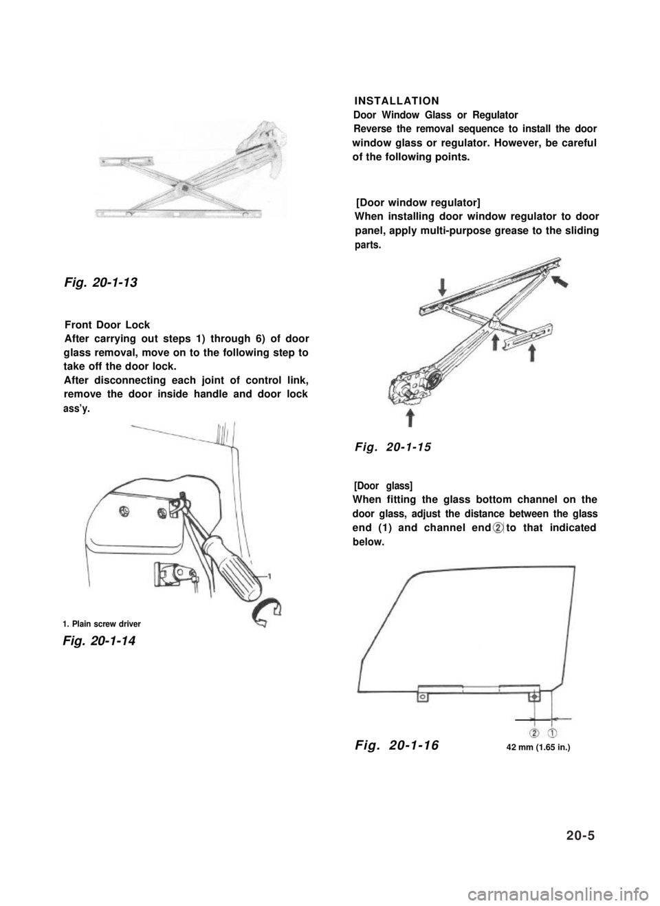
Fig. 20-1-13
Front Door Lock
After carrying out steps 1) through 6) of door
glass removal, move on to the following step to
take off the door lock.
After disconnecting each joint of control link,
remove the door inside handle and door lock
ass’y.
1. Plain screw driver
Fig. 20-1-14
INSTALLATION
Door Window Glass or Regulator
Reverse the removal sequence to install the door
window glass or regulator. However, be careful
of the following points.
[Door window regulator]
When installing door window regulator to door
panel, apply multi-purpose grease to the sliding
parts.
Fig. 20-1-15
[Door glass]
When fitting the glass bottom channel on the
door glass, adjust the distance between the glass
end (1) and channel end to that indicated
below.
Fig. 20-1-1642 mm (1.65 in.)
20-5
Page 440 of 962
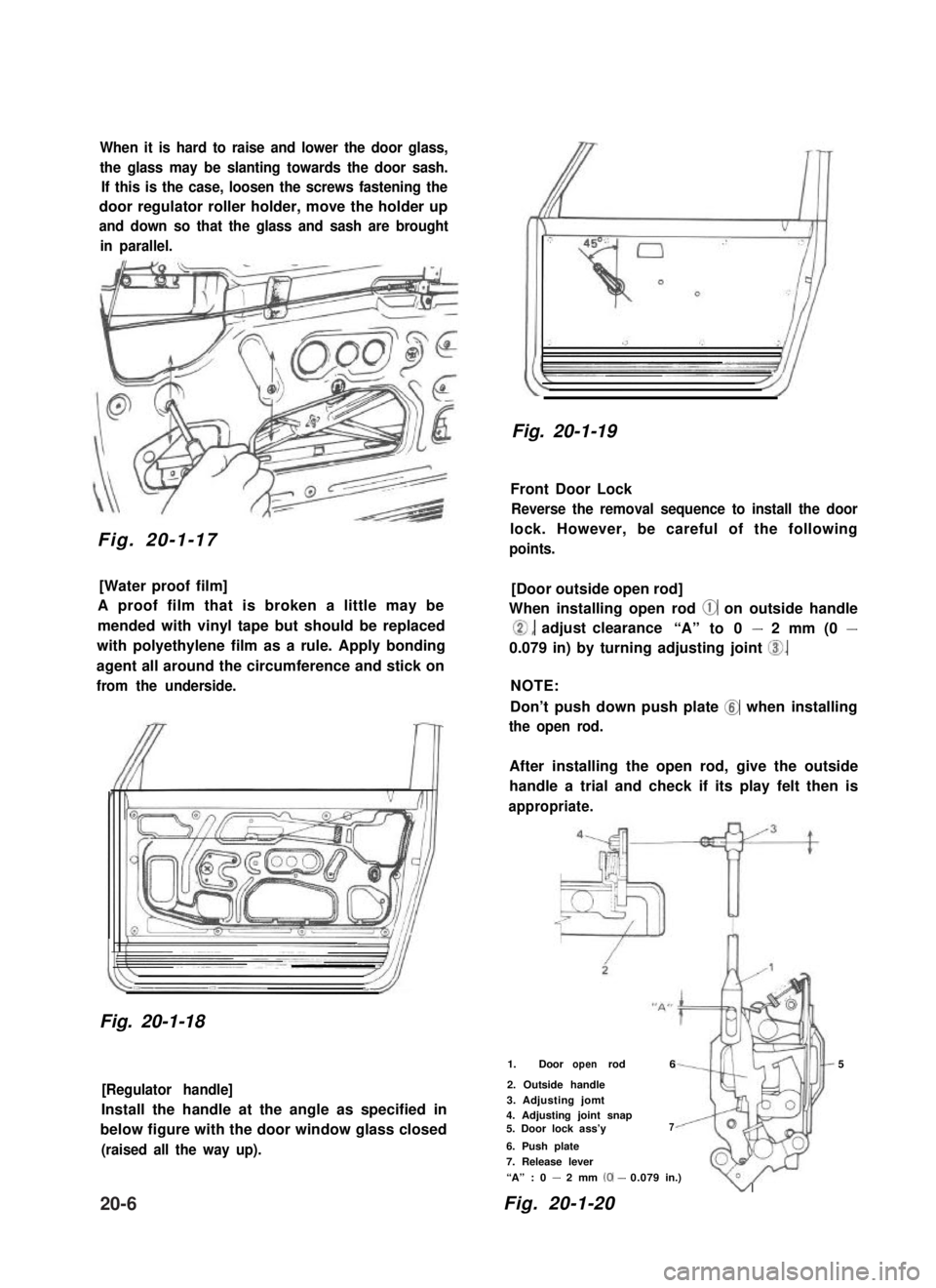
When it is hard to raise and lower the door glass,
the glass may be slanting towards the door sash.
If this is the case, loosen the screws fastening the
door regulator roller holder, move the holder up
and down so that the glass and sash are brought
in parallel.
Fig. 20-1-17
[Water proof film]
A proof film that is broken a little may be
mended with vinyl tape but should be replaced
with polyethylene film as a rule. Apply bonding
agent all around the circumference and stick on
from the underside.
Fig. 20-1-18
[Regulator handle]
Install the handle at the angle as specified in
below figure with the door window glass closed
(raised all the way up).
Fig. 20-1-19
Front Door Lock
Reverse the removal sequence to install the door
lock. However, be careful of the following
points.
[Door outside open rod]
When installing open rod @ on outside handle
0, adjust clearance“A” to 0 - 2 mm (0 -
0.079 in) by turning adjusting joint 0.
NOTE:
Don’t push down push plate @ when installing
the open rod.
After installing the open rod, give the outside
handle a trial and check if its play felt then is
appropriate.
1. Door rodopen65
2. Outside handle
3. Adjusting jomt4. Adjusting joint snap5. Door lock ass’y7
6. Push plate
7. Release lever
“A” : 0 - 2 mm (0-0.079in.)
Fig. 20-1-20
v
20-6
Page 441 of 962
![SUZUKI GRAND VITARA 1987 Service Repair Manual [Door lock inside handle]
Fit the inside handle, adjusting the clearance
between inside open lever @I and outside open
lever @I of the door lock to 0 - 2 mm (0 -
0,079 in) by moving the inside handle SUZUKI GRAND VITARA 1987 Service Repair Manual [Door lock inside handle]
Fit the inside handle, adjusting the clearance
between inside open lever @I and outside open
lever @I of the door lock to 0 - 2 mm (0 -
0,079 in) by moving the inside handle](/img/20/57437/w960_57437-440.png)
[Door lock inside handle]
Fit the inside handle, adjusting the clearance
between inside open lever @I and outside open
lever @I of the door lock to 0 - 2 mm (0 -
0,079 in) by moving the inside handle remote
control rod @ in the arrow direction given in
below figure.
After installation, give it a trial and check if its
play felt then is appropriate.
8. Inside open lever
9. Outside open lever
10. Control rod
11. Door lock striker“B” :0 - 2 mm (0 - 0.079 in.)
Fig. 20-1-21
[Door lock rod pin]
Fix the lock rod with rod pin securely as illust-
rated below.
Rod pin
Fig. 20-1-22
[Door lock striker]
Increase or decrease striker spacers fitted in “A”
position behind the striker to adjust dimensions
to below values as shown in below figure.
After adjustment, check the difference in level
between the door and
there is difference by
striker to right or left.
body and adjust when
moving the door lock
Clearance3.0 mm
(0.12 in.)Spacer fitting position “A”r
Striker
Door lock base\JIA4Yl
y <1 Door inner panelDimension
H 12.7-14.7mm(0.499 - 0.579 in.)
Fig. 20-1-23
Move the striker base up and down so that
striker shaft aligns with the center of the groove
of the door lock (the clearance between the shaft
of door lock striker and lock base is 1.0 mm
(0.04 in.)) in the vertical direction.
CAUTION:
l The striker should be placed vertically.
l Do not adjust the door lock.
Door lock cam
Fig. 20-1-24
20-7
Page 445 of 962
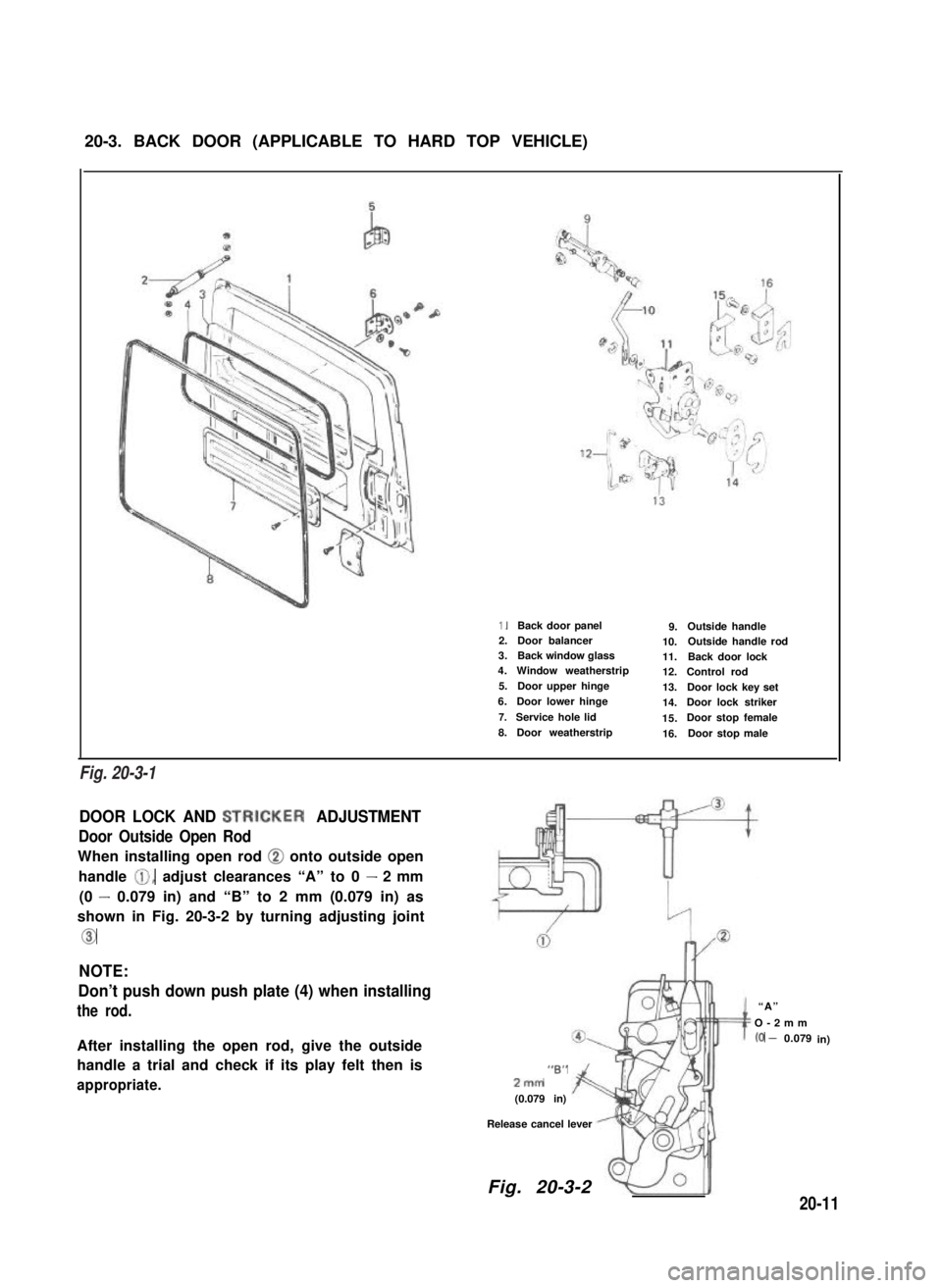
20-3. BACK DOOR (APPLICABLE TO HARD TOP VEHICLE)
1.Back door panel9.Outside handle2.Door balancer 10.Outside handle rod3.Back window glass11.Back door lock4.Window weatherstrip12.Control rod5.Door upper hinge13.Door lock key set6.Door lower hinge14.Door lock striker7.Service hole lid15.Door stop female8.Door weatherstrip16.Door stop male
DOOR LOCK AND STRICKER ADJUSTMENT
Door Outside Open Rod
When installing open rod @ onto outside open
handle 0, adjust clearances “A” to 0 - 2 mm
(0 - 0.079 in) and “B” to 2 mm (0.079 in) as
shown in Fig. 20-3-2 by turning adjusting joint
Co
NOTE:
Don’t push down push plate (4) when installing
the rod.
After installing the open rod, give the outside
handle a trial and check if its play felt then is
appropriate.
“B”2mm
(0.079 in)
Release cancel lever
“A”
O-2mm
(0 - 0.079in)
Fig. 20-3-2
20-11
Fig. 20-3-1
Page 446 of 962
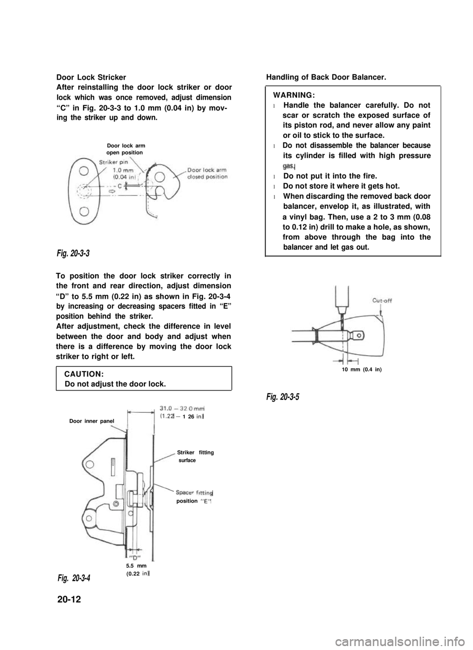
Door Lock Stricker
After reinstalling the door lock striker or door
lock which was once removed, adjust dimension
“C” in Fig. 20-3-3 to 1.0 mm (0.04 in) by mov-
ing the striker up and down.
Door lock armopen position
Fig. 20-3-3
To position the door lock striker correctly in
the front and rear direction, adjust dimension
“D” to 5.5 mm (0.22 in) as shown in Fig. 20-3-4
by increasing or decreasing spacers fitted in “E”
position behind the striker.
After adjustment, check the difference in level
between the door and body and adjust when
there is a difference by moving the door lock
striker to right or left.
CAUTION:
Do not adjust the door lock.
t---l
31.0-320mm
Door inner panel(1.22 - 1 26 in)
Striker fitting
/ surface
’ Spacer fitting
position “E”
Handling of Back Door Balancer.
WARNING:
l Handle the balancer carefully. Do not
scar or scratch the exposed surface of
its piston rod, and never allow any paint
or oil to stick to the surface.
l Do not disassemble the balancer because
its cylinder is filled with high pressure
Qas.
l Do not put it into the fire.
l Do not store it where it gets hot.
l When discarding the removed back door
balancer, envelop it, as illustrated, with
a vinyl bag. Then, use a 2 to 3 mm (0.08
to 0.12 in) drill to make a hole, as shown,
from above through the bag into the
balancer and let gas out.
It-10 mm (0.4 in)
Fig. 20-3-5
5.5 mm
(0.22 in)Fig. 20-3-4
20-12
Page 468 of 962
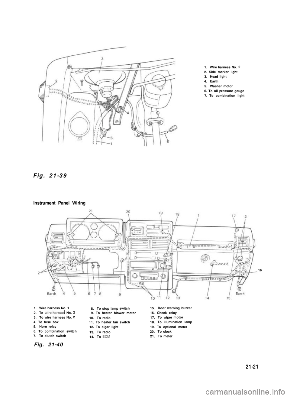
Fig. 21-39
Instrument Panel Wiring
1.Wire harness No.2
2. Side marker light3.Head light
4.Earth
5.Washer motor
6. To oil pressure gauge
7. To combination light
16
1.Wire harness No. 1
2.To wire~harness No.2
3.To wire harness No.2
4. To fuse box5.Horn relay
6. To combination switch7.To clutch switch
8.Tostop lampswitch15.Doorwarning buzzer
9. To heater blower motor16. Check relay
10.Toradio17.To wipermotor
Il. To heater fan switch18.To illumination lamp
12. To cigar light19. To optional meter
13.Toradio20.Toclock
14.ToECM21.Tometer
Fig. 21-40
21-21