warning SUZUKI GRAND VITARA 1987 Service Repair Manual
[x] Cancel search | Manufacturer: SUZUKI, Model Year: 1987, Model line: GRAND VITARA, Model: SUZUKI GRAND VITARA 1987Pages: 962, PDF Size: 27.87 MB
Page 4 of 962
O-2. STANDARD SHOP PRACTICES
1. Protect painted surfaces of the body, and
avoid staining or tearing seats. When working
on fenders and seats, be sure to cover them
up with sheets.
2. Disconnect negative terminal connection of
the battery when working on any electrical
part or component. This is necessary for
avoiding electrical shocks and short-circuit-
ing, and is very simple to accomplish: merely
loosen wing nut on negative terminal and
separate cable from terminal post.
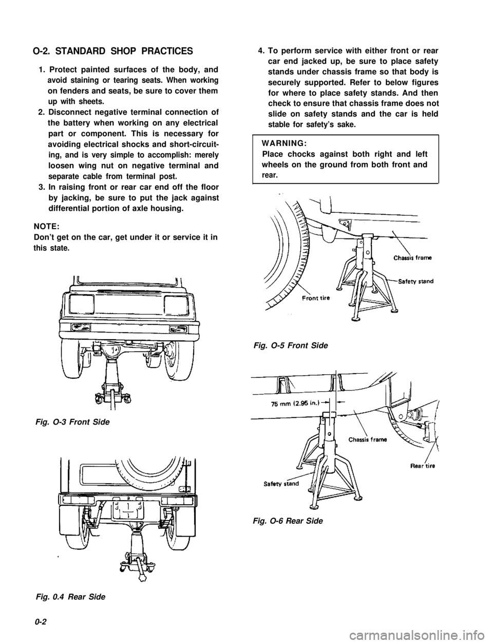
3. In raising front or rear car end off the floor
by jacking, be sure to put the jack against
differential portion of axle housing.
NOTE:
Don’t get on the car, get under it or service it in
this state.
Fig. O-3 Front Side
4. To perform service with either front or rear
car end jacked up, be sure to place safety
stands under chassis frame so that body is
securely supported. Refer to below figures
for where to place safety stands. And then
check to ensure that chassis frame does not
slide on safety stands and the car is held
stable for safety’s sake.
WARNING:
Place chocks against both right and left
wheels on the ground from both front and
rear.
Fig. O-5 Front Side
&
Fig. O-6 Rear Side
Fig. 0.4 Rear Side
0-2
Page 5 of 962
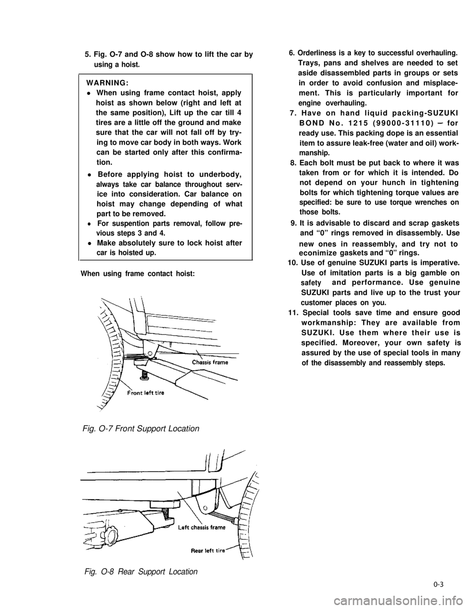
5. Fig. O-7 and O-8 show how to lift the car by
using a hoist.
WARNING:
l When using frame contact hoist, apply
hoist as shown below (right and left at
the same position), Lift up the car till 4
tires are a little off the ground and make
sure that the car will not fall off by try-
ing to move car body in both ways. Work
can be started only after this confirma-
tion.
l Before applying hoist to underbody,
always take car balance throughout serv-
ice into consideration. Car balance on
hoist may change depending of what
part to be removed.
lFor suspention parts removal, follow pre-
vious steps 3 and 4.
l Make absolutely sure to lock hoist after
car is hoisted up.
When using frame contact hoist:
6. Orderliness is a key to successful overhauling.
Trays, pans and shelves are needed to set
aside disassembled parts in groups or sets
in order to avoid confusion and misplace-
ment. This is particularly important for
engine overhauling.
7. Have on hand liquid packing-SUZUKI
BOND No. 1215 (99000-31110) - for
ready use. This packing dope is an essential
item to assure leak-free (water and oil) work-
manship.
8. Each bolt must be put back to where it was
taken from or for which it is intended. Do
not depend on your hunch in tightening
bolts for which tightening torque values are
specified: be sure to use torque wrenches on
those bolts.
9. It is advisable to discard and scrap gaskets
and “0” rings removed in disassembly. Use
new ones in reassembly, and try not to
econimize gaskets and “0” rings.
10. Use of genuine SUZUKI parts is imperative.
Use of imitation parts is a big gamble on
safetyand performance. Use genuine
SUZUKI parts and live up to the trust your
customer places on you.
11. Special tools save time and ensure good
workmanship: They are available from
SUZUKI. Use them where their use is
specified. Moreover, your own safety is
assured by the use of special tools in many
of the disassembly and reassembly steps.
Fig. O-7 Front Support Location
Fig. O-8 Rear Support Location
0-3
Page 23 of 962
NOTE:
Steps 1) - 6) outlined above must be performed
with ENGINE NOT RUNNING. For step 7),
be sure to have adequate ventilation while
engine is running
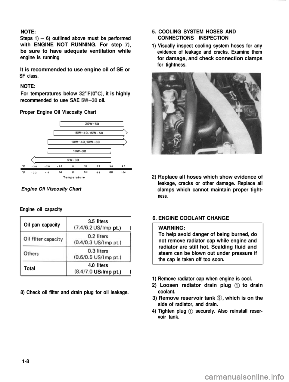
It is recommended to use engine oil of SE or
SF class.
NOTE:For temperatures below
32”F(O”C), it is highly
recommended to use SAE 5W-30 oil.
Proper Engine Oil Viscosity Chart
12OW-50
lSW-40.15w-501
Ilow-4O.lOW-50
Ilow-30I
5w-30I“C-3 0 -2
0 -1
0 0 102
0
30 4
0
OF-2 2 -
4 14
32506886104
Temperatur e
Engine Oil Viscosity Chart
Engine oil capacity
Oil pan capacity 3.5 liters (7.4/6.2
US/Imp pt.)I
Total 4.0 liters(8.4/7.0 US/Imp pt.)I
8) Check oil filter and drain plug for oil leakage.
5. COOLING SYSTEM HOSES AND
CONNECTIONS INSPECTION
1) Visually inspect cooling system hoses for any
evidence of leakage and cracks. Examine them
for damage, and check connection clamps
for tightness.
2) Replace all hoses which show evidence of
leakage, cracks or other damage. Replace all
clamps which cannot maintain proper tight-
ness.
6. ENGINE COOLANT CHANGE
WARNING:
To help avoid danger of being burned, do
not remove radiator cap while engine and
radiator are still hot. Scalding fluid and
steam can be blown out under pressure if
the cap is taken off too soon.
1) Remove radiator cap when engine is cool.
2) Loosen radiator drain plug @
to drain
coolant.
3) Remove reservoir tank 0, which is on the
side of radiator, and drain.
4) Tighten plug
@ securely. Also reinstall reser-
voir tank.
1-8
Page 25 of 962

CAUTION:
When changing engine coolant, use mixture
of 56% water and 50% GOLDEN CRUISER
1200for the market where ambient tem-
perature falls lower than -16°C (3°F) in
winter and mixture of 70% water and
30% GOLDEN CRUISER 1200for the
market where ambient temperature doesn’t
fall lower than -16°C (3” F).
Even in a market where no freezing tempe-
rature is anticipated, mixture of 70% water
and 30% GOLDEN CRUISER 1200
should be used for the purpose of corro-
sion protection and lubrication.
7. EXHAUST PIPES AND MOUNTINGS
INSPECTION
1.Drain plug
1. Reservoir tank cap2. Reservoir tank
3. Arrow marks
5) Fill radiator with specified amount of coolant,
and run engine for 2 or 3 minutes at idle.
This drives out any air which may still be
trappedwithincoolingsystem.STOP
ENGINE. Add coolant as necessary until
coolant level reaches the filler throat of
radiator. Reinstall radiator cap.
6) Add coolant to reservoir tank so that the level
aligns with Full mark. Then, reinstall cap
aligning the arrow marks on the tank and cap.
r.
COOLANT CAPACITY
Engine, radiator and4.2 liters
heater(8.9/7.4 US/Imp pt.)
Reservoir tank0.6 liters
(1.3/1.1 US/Imp pt.)
ITotal4.8 liters
(10.1/8.4US/lmp pt.)
WARNING:
To avoid danger of being burned, do not
touch exhaust system when system is hot.
Any service on exhaust system should be
performed when system is cool.
When carrying out periodic maintenance, or the
car is raised for other service, check exhaust
system as follows:
l Check rubber mountings for damage, deterio-
ration, and out of position.
l Check exhaust system for leakage, loose
connections, dents, and damages.
If bolts or nuts are loose, tighten them to
specification. Refer to below chart for torque
specification.
l Check nearby body areas for damaged, miss-
ing, or mispositioned parts, open seams,
holes, loose connections or’ other defects
which could permit exhaust fumes to seep
into the car.
l Make sure that exhaust system components
have enough clearance from the underbody to
avoid overheating and possible damage to the
floor carpet.
l Any defects should be fixed at once.
IBolts and nutTightening torqueI
40-80 N-m
Exhaustpipebolts4.0-6.0 kg-m
29.0-43.0 lb-ft
Muffler nuts
18 - 28 N-m
1.8 - 2.8 kg-m
13.5 - 20.0 lb-ft
Replace center pipe rubber mounting and muffler
rubber mountings with new ones periodically.
l-9
Page 27 of 962
1. CHARCOAL CANISTER REPLACEMENT
WARNING:
The following cautions should be always
observed.
l Disconnect negative cable at battery.
l DO NOT smoke and place “NO SMOK-
ING” signs near work area.
l Be sure to have COZ fire extinguisher
handy.
l Wear safety glasses.
l To release the fuel vapor pressure in
fuel tank, remove the fuel tank cap and
then reinstall it.
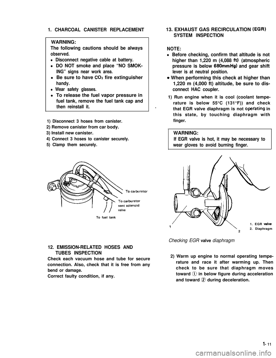
1) Disconnect 3 hoses from canister.
2) Remove canister from car body.
3) Install new canister.
4) Connect 3 hoses to canister securely.
5) Clamp them securely.
//valve
To fuel tank
12. EMISSION-RELATED HOSES AND
TUBES INSPECTION
Check each vacuum hose and tube for secure
connection. Also, check that it is free from any
bend or damage.
Correct faulty condition, if any.
13. EXHAUST GAS RECIRCULATION (EGR)
SYSTEM INSPECTION
NOTE:
l Before checking, confirm that altitude is not
higher than 1,220 m (4,088 ftt) (atmospheric
pressure is below 680mmHg) and gear shift
lever is at neutral position.
o When performing this check at higher than
1,220 m (4,000 ft) altitude, be sure to dis-
connect HAC coupler.
.
1) Run engine when it is cool (coolant tempe-
rature is below 55°C (131°F)) and check
that EGR valve diaphragm is not operating in
this state, by touching diaphragm with
finger.
WARNING:
If EGR valve is hot, it may be necessary to
wear gloves to avoid burning finger.
1. EGR valve
22. Diaphragm
Checking EGR valve diaphragm
2) Warm up engine to normal operating tempe-
rature and race it after warming up. Then
check to be sure that diaphragm moves
toward @ in below figure during acceleration
and toward @ during deceleration.
l- 11
Page 30 of 962
21. FUEL TANK CAP GASKET INSPECTION
AND REPLACEMENT
Visually inspect gasket of fuel tank cap. If it is
damaged or deteriorated, replace it with new
one.
22. AIR CLEANER ELEMENT
REPLACEMENT
1) Remove air cleaner cap.
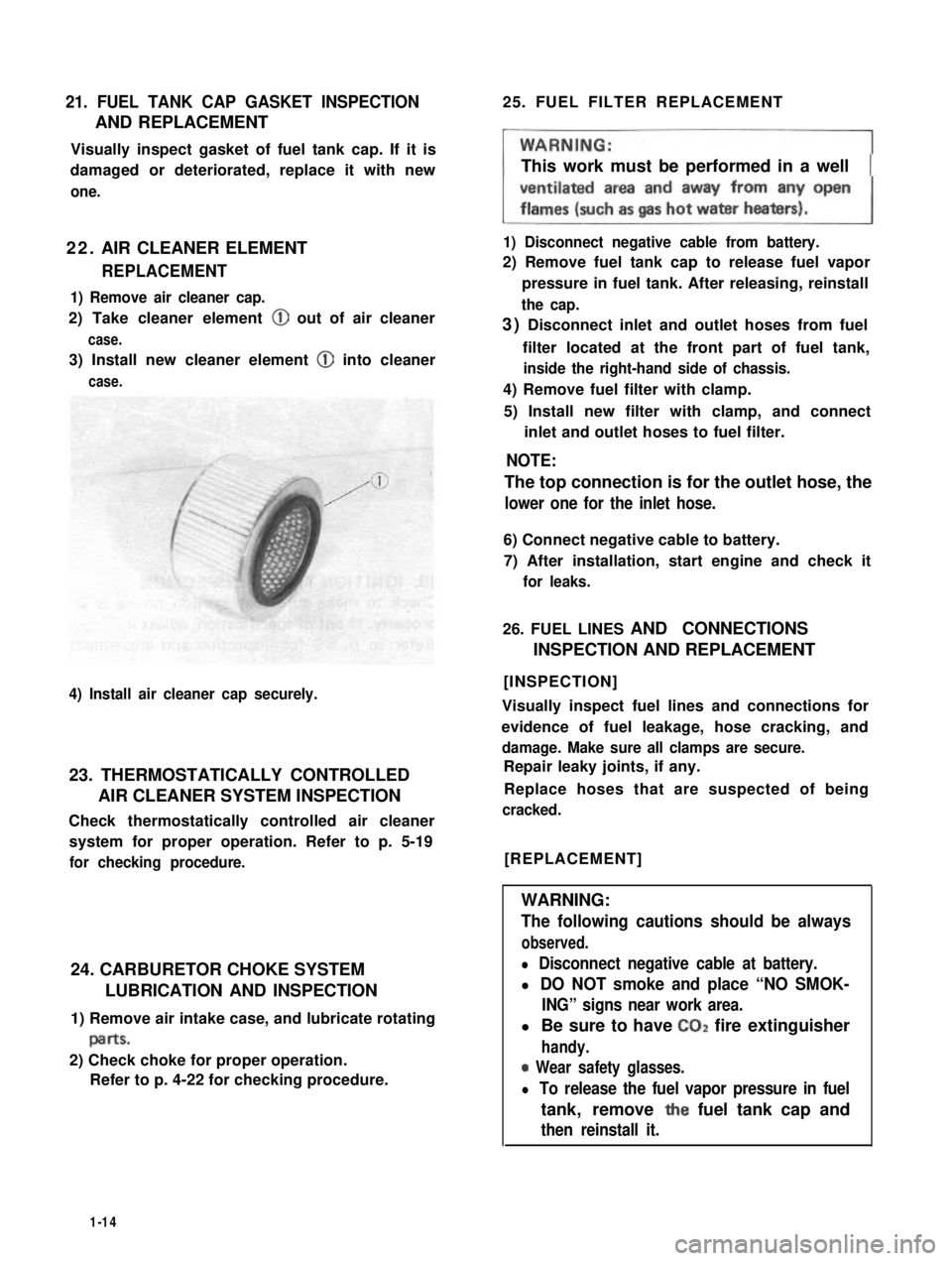
2) Take cleaner element @ out of air cleaner
case.
3) Install new cleaner element @ into cleaner
case.
4) Install air cleaner cap securely.
23. THERMOSTATICALLY CONTROLLED
AIR CLEANER SYSTEM INSPECTION
Check thermostatically controlled air cleaner
system for proper operation. Refer to p. 5-19
for checking procedure.
24. CARBURETOR CHOKE SYSTEM
LUBRICATION AND INSPECTION
1) Remove air intake case, and lubricate rotating
paItS.
2) Check choke for proper operation.
Refer to p. 4-22 for checking procedure.
25. FUEL FILTER REPLACEMENT
This work must be performed in a well
1) Disconnect negative cable from battery.
2) Remove fuel tank cap to release fuel vapor
pressure in fuel tank. After releasing, reinstall
the cap.
3) Disconnect inlet and outlet hoses from fuel
filter located at the front part of fuel tank,
inside the right-hand side of chassis.
4) Remove fuel filter with clamp.
5) Install new filter with clamp, and connect
inlet and outlet hoses to fuel filter.
NOTE:
The top connection is for the outlet hose, the
lower one for the inlet hose.
6) Connect negative cable to battery.
7) After installation, start engine and check it
for leaks.
26. FUEL LINES AND CONNECTIONS
INSPECTION AND REPLACEMENT
[INSPECTION]
Visually inspect fuel lines and connections for
evidence of fuel leakage, hose cracking, and
damage. Make sure all clamps are secure.
Repair leaky joints, if any.
Replace hoses that are suspected of being
cracked.
[REPLACEMENT]
WARNING:
The following cautions should be always
observed.
l Disconnect negative cable at battery.
l DO NOT smoke and place “NO SMOK-
ING” signs near work area.
l Be sure to have CO2 fire extinguisher
handy.
0 Wear safety glasses.
l To release the fuel vapor pressure in fuel
tank, remove the fuel tank cap and
then reinstall it.
1-14
Page 35 of 962
3) Install spindle, bearings, wheel hub, bearing
nut and brake disc referring to INSTALLA-
TION (p. 17-12) of SECTION 17.
4) Adjust bearing preload and then tighten
bearing lock nut to specification. Refer to
MAINTENANCE (p. 17-21) of SECTION 17.
5) Install drive flange or free wheeling hub (if
equipped), brake caliper with mounting and
wheel referring to INSTALLATION (p. 17-
12) of SECTION 17.
For tightening torque of each bolt and nut,
refer to torque table (p. 17-26) of SECTION
17.
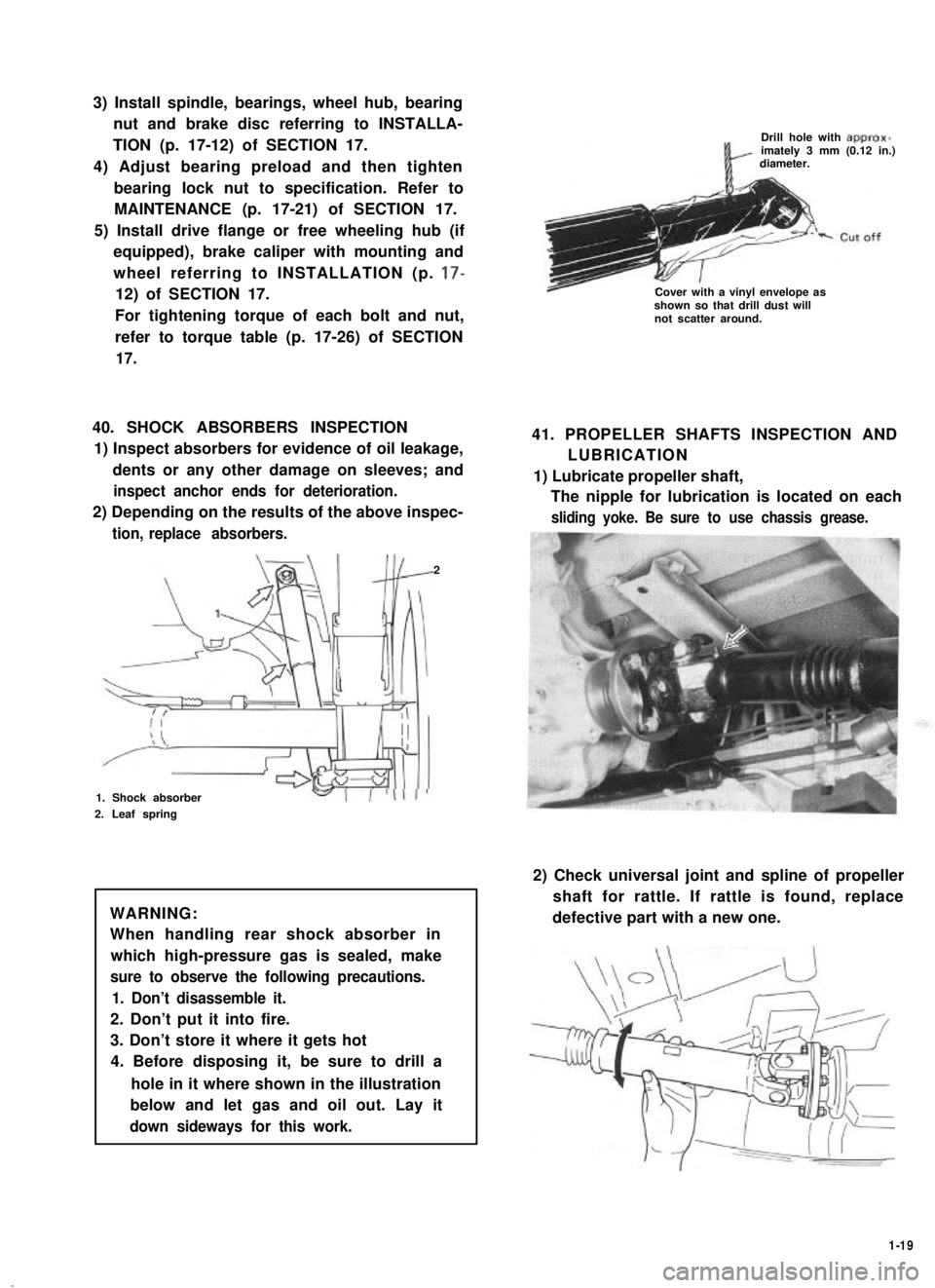
40. SHOCK ABSORBERS INSPECTION
1) Inspect absorbers for evidence of oil leakage,
dents or any other damage on sleeves; and
inspect anchor ends for deterioration.
2) Depending on the results of the above inspec-
tion, replace absorbers.
2
1. Shock absorber
2. Leaf spring
WARNING:
When handling rear shock absorber in
which high-pressure gas is sealed, make
sure to observe the following precautions.
1. Don’t disassemble it.
2. Don’t put it into fire.
3. Don’t store it where it gets hot
4. Before disposing it, be sure to drill a
hole in it where shown in the illustration
below and let gas and oil out. Lay it
down sideways for this work.
Drill hole with approx-imately 3 mm (0.12 in.)diameter.
Cover with a vinyl envelope asshown so that drill dust willnot scatter around.
41. PROPELLER SHAFTS INSPECTION AND
LUBRICATION
1) Lubricate propeller shaft,
The nipple for lubrication is located on each
sliding yoke. Be sure to use chassis grease.
2) Check universal joint and spline of propeller
shaft for rattle. If rattle is found, replace
defective part with a new one.
1-19
Page 38 of 962
FINAL INSPECTION
Carry out road test in safe place.
WARNING:
When carrying out the following road
tests, select a safe place where no man or
no running car is seen so as to prevent any
accident.
1) Engine start
Check engine start for readiness.
2) Clutch
Check the following:
l that clutch is completely released when
depressing clutch pedal,
l that no slipping clutch occurs when releas-
ing pedal and accelerating,
l and that clutch itself is free from any
abnormal condition.
3) Gearshift Lever (Transmission and Transfer)
Check gearshift lever for smooth shifting
to all positions and for good performance of
transmission and transfer in any position.
4) Brake
[Foot brake]
Check the following when depressing brake
pedal while driving;
l that brake works properly,
l that it is free from noise,
l and that braking force applies equally on
all wheels.
[Parking brake]
Check to ensure that parking brake is fully
effective when the car is stopped on the slop
and brake lever is pulled all the way.
5) Steering
Check to ensure that steering wheel is free
from instability, or abnormally heavy feeling
while driving.
1-22
Page 51 of 962

Condition
Excessive pedal travel
(Pedal stroke too
large)
Possible cause
1. Partial brake system failure
2. Insufficient fluid in master
cylinder reservoirs
Correction
Check diagonal brake systems and
repair as necessary
Fill reservoirs with approved brake
fluid. Check for leaks and air in
brake systems. Check warning light.
Bleed system if necessary.
3. Air in system (Pedal soft/spongy)Bleed system
4. Rear brake system not adjustedAdjust rear brakes (Repair auto
(malfunctioning auto adjustingadjusting mechanism)
mechanism)
5. Bent brake shoesReplace brake shoes
6. Worn rear brake shoesReplace brake shoes.
Dragging brakes (A
very light drag is pre-
sent in all disc brakes
immediately after
pedal is released)
1. Master cylinder pistons not
returning correctly
2. Clogged return port in master
cylinder
3. Restricted brake tubes or hoses
4. Incorrect parking brake
adjustment
5. Weakened or broken return
springs in the brake
Repair master cylinder
Clean
Check for soft hoses or damaged tubes
and replace with new hoses and/or
new double-walled steel brake tubing
Check and adjust to correct specifica-
tions
Replace
6. Sluggish parking-brake cables or
linkage
Repair or replace
7. Wheel cylinder or caliper piston
sticking
Repair as necessary
Pedal pulsation1. Damaged or loose wheel bearingsReplace wheel bearings
(Pedal pulsates when2. Excessive disc lateral runout Check per instructions. If not within
depressed for braking)specifications, replace or machine the
disc.
3. Parallelism not within specifica-Check per instructions. If not within
tionsspecifications, replace or machine the
disc.
4. Rear drums out of roundCheck runout.
Braking noise1. Glazed shoe linings, or foreignRepair or replace shoe lining
matters stuck to linings
2. Worn or distorted shoe liningsReplace shoe lining (or pad)
3. Loose front wheel bearingsReplace wheel bearings
4. Distorted backing plates or looseReplace or retighten securing bolts
mounting bolts
2-13
Page 127 of 962
REMOVAL AND INSTALLATION
Removal and installation of carburetor
place where no fire is used around.
Removal
1) Disconnect negative battery cord from
battery.
2) Drain coolant.
WARNING:
To help avoid the danger of being burned,
do not remove the drain plug and the
radiator cap while the engine and radiator
are still hot. Scalding fluid and steam can
be blown out under pressure if the plug
and cap are taken off too soon.
3) Remove air intake case from carburetor.
4) Disconnect micro switches, switch vent sole-
noid valve, fuel cut solenoid valve and MCSV
lead wires at their couplers.
5) Disconnect VSV coupler from VSV.
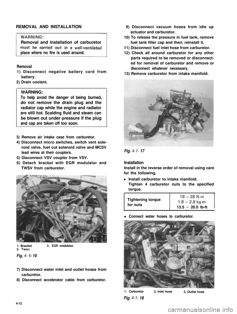
6) Detach bracket with EGR modulator and
TWSV from carburetor.
1. Bracket3.EGRmodulator2. Twsv
Fig. 4- 1-16
7) Disconnect water inlet and outlet hoses from
carburetor.
8) Disconnect accelerator cable from carburetor.
9) Disconnect vacuum hoses from idle up
actuator and carburetor.
10) To release the pressure in fuel tank, remove
fuel tank filler cap and then, reinstall it.
11) Disconnect fuel inlet hose from carburetor.
12) Check all around carburetor for any other
parts required to be removed or disconnect-
ed for removal of carburetor and remove or
disconnect whatever necessary.
13) Remove carburetor from intake manifold.
Fig. 4- 7- 17
Installation
Install in the reverse order of removal using care
for the following.
l Install carburetor to intake manifold.
Tighten 4 carburetor nuts to the specified
torque.
Tightening torque
for nuts13.5 - 20.0 lb-ft
l Connect water hoses to carburetor.
1. Carburetor
Fig. 4- I- 18
2. Inlet hose3. Outlet hose
4-12