Throttle SUZUKI GRAND VITARA 1999 2.G User Guide
[x] Cancel search | Manufacturer: SUZUKI, Model Year: 1999, Model line: GRAND VITARA, Model: SUZUKI GRAND VITARA 1999 2.GPages: 656, PDF Size: 14.31 MB
Page 190 of 656
ENGINE GENERAL INFORMATION AND DIAGNOSIS (H27 ENGINE) 6-1-29
EGR VALVE (%)
This parameter indicates opening rate of EGR valve which controls the amount of EGR flow.
A/C SWITCH (ON/OFF)
ON : Command for operation being output from A/C amplifier to compressor.
OFF : Command for operation not being output.
PSP SWITCH (ON/OFF)
ON : PSP switch detects P/S operation. (high P/S pressure)
OFF : PSP switch not detects P/S operation.
PNP SIGNAL (Transmission Range Switch, P/N or D range)
Whether the transmission range switch (P/N position switch) at P or N range or at R, D, 2 or L range is displayed.
If at P or N range, “P/N range” is displayed and if at R, D, 2 or L range, “D range” is displayed.
FUEL TANK LEVEL (%)
This parameter indicates approximate fuel level in the fuel tank. As the detectable range of the fuel level sensor
is set as 0 to 100 %, however, with some models whose fuel tank capacity is smaller, the indicated fuel level may
be only 70 % even when the fuel tank is full.
ELECTRIC LOAD (ON/OFF)
ON : Small light switch ON or rear window defogger switch ON.
OFF : Small light switch OFF and rear window defogger switch OFF.
VSS (4-A/T) (km/h, MPH)
It is computed by using pulse signals from vehicle speed sensor on 4-speed automatic transmission.
THROT POS LEVEL (Throttle Position Level For 4-A/T, “0”, “1”, “2”, “3”, “4”,“5”,“6” or “7”)
This parameter indicates which level (zone) the throttle valve opening is in.
The throttle opening is divided into 8 levels (zones) from “0” (about idle position) to “7” (about full open) and sig-
nals are assigned to each opening level (zone). PCM controls the automatic gear change of the automatic trans-
mission by using these signals according to the signal from the TP sensor.
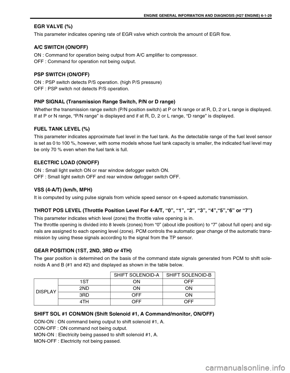
GEAR POSITION (1ST, 2ND, 3RD or 4TH)
The gear position is determined on the basis of the command state signals generated from PCM to shift sole-
noids A and B (#1 and #2) and displayed as shown in the table below.
SHIFT SOL #1 CON/MON (Shift Solenoid #1, A Command/monitor, ON/OFF)
CON-ON : ON command being output to shift solenoid #1, A.
CON-OFF : ON command not being output.
MON-ON : Electricity being passed to shift solenoid #1, A.
MON-OFF : Electricity not being passed.SHIFT SOLENOID-A SHIFT SOLENOID-B
DISPLAY1ST ON OFF
2ND ON ON
3RD OFF ON
4TH OFF OFF
Page 194 of 656
ENGINE GENERAL INFORMATION AND DIAGNOSIS (H27 ENGINE) 6-1-33
Surges
(Engine power varia-
tion under steady
throttle or cruise.
Feels like the vehicle
speeds up and down
with no change in the
accelerator pedal.)Defective spark plug
(excess carbon deposits, improper gap, and
burned electrodes, etc.)Spark plugs in Section 6F2.
Variable fuel pressure
(clogged fuel filter, kinky or damaged fuel hose
and line, faulty fuel pressure regulator)“DIAG. FLOW TABLE B-3” in this
section.
Faulty EGR system “DTC P0400 DIAG. FLOW TABLE”
in this section.
Faulty MAF sensor MAF sensor in Section 6E2.
Faulty injector Fuel injector in Section 6E2.
Faulty ECM (PCM) Inspection of ECM (PCM) and its
circuit in this section.
Excessive detonation
(The engine makes
sharp metallic knocks
that change with throt-
tle opening. Sounds
like pop corn pop-
ping.)Engine overheating Refer to “OVERHEATING” in this
table.
Faulty spark plug Spark plugs in Section 6F2.
Improper ignition timing Ignition timing in Section 6F2.
Clogged fuel filter and fuel lines Fuel pressure check in Section
6E2.
Faulty EGR system “DTC P0400 DIAG. FLOW TABLE”
in this section.
Faulty ECT sensor or MAF sensor ECT sensor or MAF sensor in Sec-
tion 6E2.
Faulty injector Fuel injector in Section 6E2.
Faulty ECM (PCM) Inspection of ECM (PCM) and its
circuit in this section.
Excessive carbon deposits in combustion
chamberPiston and cylinder head cleaning
in Section 6A2.
Poor knock sensor performance “DTC P0325 DIAG. FLOW TABLE”
in this section.
Overheating
Inoperative thermostat Thermostat in Section 6B.
Poor water pump performance Water pump in Section 6B.
Clogged or leaky radiator Radiator in Section 6B.
Improper engine oil grade Engine oil and oil filter change in
Section 0B.
Clogged oil filter or oil strainer Oil pressure check in Section 6A2.
Poor oil pump performance Oil pressure check in Section 6A2.
Dragging brakes Diagnosis in Section 5.
Slipping clutch Diagnosis in Section 7C1.
Blown cylinder head gasket Cylinder head inspection in Section
6A2. Condition Possible Cause Correction
Page 198 of 656
ENGINE GENERAL INFORMATION AND DIAGNOSIS (H27 ENGINE) 6-1-37
TERMINAL CIRCUIT NORMAL VOLTAGE CONDITION
E61-1Power source for CO adjusting
resistor (if equipped)10 – 14 V Ignition switch ON
E61-2 Power source for back up 10 – 14 V Ignition switch ON and OFF
E61-3 – – –
E61-4Cruise control module
(throttle opening signal)
(if equipped)Ignition switch ON, Voltage varies as specified at figure in
cruise control diagnosis of Section 8E while throttle valve is
opened gradually.
E61-5Duty output terminal
(vehicle with monitor connector)0 – 1 V Ignition switch ON
E61-6 Tachometer 0 – 1 V Ignition switch ON, engine stops
E61-7Malfunction indicator lamp
(“SERVICE ENGINE SOON” lamp)0 – 2.5 V Ignition switch ON, engine stops
10 – 14 V Engine running
E61-8 A/C cut signal (if equipped)0 – 1.5 V A/C is not operating
10 – 14 V A/C is operating
E61-9 Main relay10 – 14 V Ignition switch OFF
0 – 2 VIgnition switch ON or for 4 seconds
after ignition switch OFF
E61-10 CO adjusting resistor (if equipped) – –
E61-11 – – –
E61-12Data link connector (5V)
(Vehicle with monitor connector)4 – 6 V Ignition switch ON
E61-13 Data link connector (12V) 10 – 14 V Scan tool not connected to DLC
E61-14Test switch terminal
(Vehicle with monitor connector)10 – 14 V Ignition switch ON
E61-15 Rear defogger switch (if equipped)0 – 1.5 VIgnition switch ON, rear defogger
switch OFF
10 – 14 VIgnition switch ON, rear defogger
switch
E61-16 Heater blower switch10 – 14 VIgnition switch ON, heater blower
switch OFF
0 – 1.5 VIgnition switch ON, heater blower
switch ON
E61-17 A/C signal (if equipped)10 – 14 VIgnition switch ON, A/C switch or
heater blower switch OFF
0 – 1 VIgnition switch ON, A/C switch ON
and heater blower switch ON
E61-18 – – –
E61-19 “4WD” lamp0 – 1 VIgnition switch ON, Transfer lever :
4H or 4L range
10 – 14 VIgnition switch ON, Transfer lever :
2H range
E61-20 “O/D OFF” lamp (A/T vehicle)0 – 1 VFor 4 sec. after ignition switch ON
or overdrive cut switch ON
10 – 14 VAfter 4 sec. from ignition switch ON
and overdrive cut switch OFF
E61-21 “POWER” lamp (A/T vehicle)0 – 1 VIgnition switch ON, P/N change
switch : POWER mode
10 – 14 VIgnition switch ON, P/N change
switch : NORMAL mode
Page 200 of 656
ENGINE GENERAL INFORMATION AND DIAGNOSIS (H27 ENGINE) 6-1-39
C51-3-9 Throttle position sensor0.5 – 1.2 VIgnition switch ON, Throttle valve at
idle position
3.4 – 4.7 VIgnition switch ON, Throttle valve at
full open position
C51-3-10 Mass air flow sensor1.0 – 1.6 V Ignition switch ON and engine stops
1.7 – 2.0 V With engine running at idle speed
C51-3-11Heated oxygen sensor-1 (bank 1)
(if equipped)Deflects between
over and under 0.45 VWhile engine running at 2,000 r/min.
for 1 min. or longer after warmed up
C51-3-12 Ground for TP sensor – –
C51-3-13 Power source for TP sensor
4.75 – 5.25 V Ignition switch ON
C51-3-14 Power source for MAP sensor
C51-3-15 Power source 10 – 14 V Ignition switch ON
C51-3-16 – – –
C51-3-17 Ground – –
C51-3-18Pressure switch in 4WD air pump
assembly10 – 14 VIgnition switch ON, Transfer lever :
4H or 4L range
0 – 1 VIgnition switch ON, Transfer lever :
2H range
C51-3-19 – – –
C51-3-20 Ignition switch 10 – 14 V Ignition switch ON
C51-3-21Heated oxygen sensor-1 (bank 2)
(if equipped)Deflects between over
and under 0.45 VWhile engine running at 2,000 r/min.
for 1 min. or longer after warmed up
C51-3-22Heated oxygen sensor-2 (bank 1)
(if equipped)Deflects between over
and under 0.45 VWhile engine running at 2,000 r/min.
for 1 min. or longer after warmed up
C51-3-23Heated oxygen sensor-2 (bank 2)
(if equipped)Deflects between over
and under 0.45 VWhile engine running at 2,000 r/min.
for 1 min. or longer after warmed up
C51-3-24 Ground for ECT sensor – –
C51-3-25 Ground for IAT sensor, MAP sensor – –
C51-3-26 Ground for CMP sensor – –
C51-1-1 Shift solenoid B (A/T vehicle) 0 – 1 V Ignition switch ON
C51-1-2 Shift solenoid A (A/T vehicle) 10 – 14 V Ignition switch ON
C51-1-3 – – –
C51-1-4 IAC valve (stepper motor coil 2) – –
C51-1-5 IAC valve (stepper motor coil 1) – –
C51-1-6Transmission range switch “R”
(A/T vehicle)10 – 14 VIgnition switch ON, selector lever :
“R” range
0 – 1 VIgnition switch ON, selector lever :
Other than “R”
C51-1-7Transmission range switch “P”
(A/T vehicle)10 – 14 VIgnition switch ON, selector lever :
“P” range
0 – 1 VIgnition switch ON, selector lever :
Other than “P” range
C51-1-8 TCC solenoid (A/T vehicle) 0 – 1 V Ignition switch ON
C51-1-9 4WD air pump assembly10 – 14 VIgnition switch ON, Transfer lever :
4H or 4L range
0 – 1 VIgnition switch ON, Transfer lever :
2H range TERMINAL CIRCUIT NORMAL VOLTAGE CONDITION
Page 215 of 656
6-1-54 ENGINE GENERAL INFORMATION AND DIAGNOSIS (H27 ENGINE)
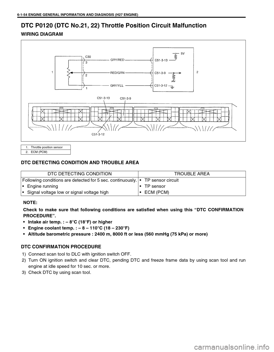
DTC P0120 (DTC No.21, 22) Throttle Position Circuit Malfunction
WIRING DIAGRAM
DTC DETECTING CONDITION AND TROUBLE AREA
DTC CONFIRMATION PROCEDURE
1) Connect scan tool to DLC with ignition switch OFF.
2) Turn ON ignition switch and clear DTC, pending DTC and freeze frame data by using scan tool and run
engine at idle speed for 10 sec. or more.
3) Check DTC by using scan tool.
1. Throttle position sensor
2. ECM (PCM)
DTC DETECTING CONDITION TROUBLE AREA
Following conditions are detected for 5 sec. continuously.
• Engine running
• Signal voltage low or signal voltage high• TP sensor circuit
•TP sensor
•ECM (PCM)
NOTE:
Check to make sure that following conditions are satisfied when using this “DTC CONFIRMATION
PROCEDURE”.
Intake air temp. : – 8°C (18°F) or higher
Engine coolant temp. : – 8 – 110°C (18 – 230°F)
Altitude barometric pressure : 2400 m, 8000 ft or less (560 mmHg (75 kPa) or more)
Page 216 of 656
ENGINE GENERAL INFORMATION AND DIAGNOSIS (H27 ENGINE) 6-1-55
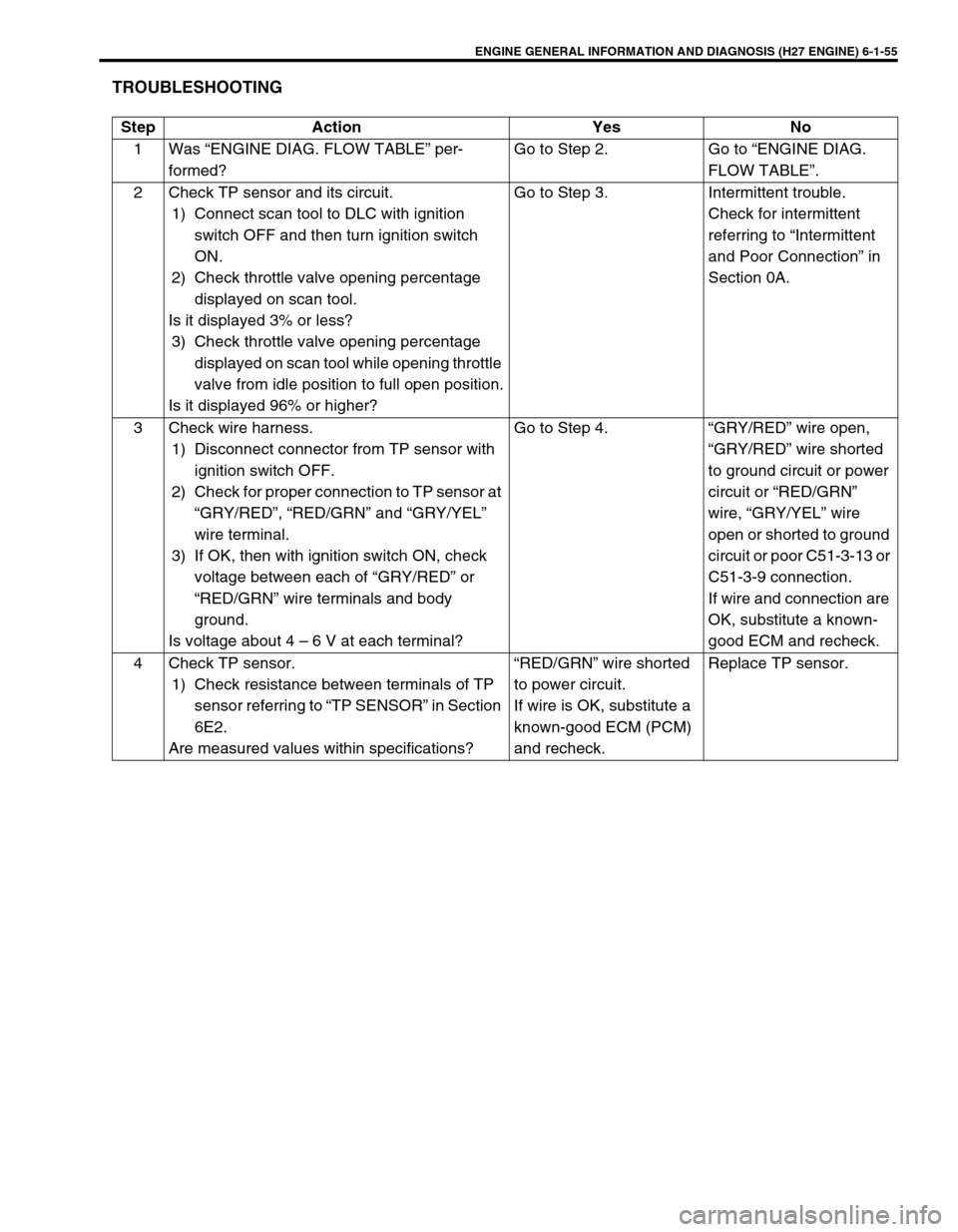
TROUBLESHOOTING
Step Action Yes No
1 Was “ENGINE DIAG. FLOW TABLE” per-
formed?Go to Step 2. Go to “ENGINE DIAG.
FLOW TABLE”.
2 Check TP sensor and its circuit.
1) Connect scan tool to DLC with ignition
switch OFF and then turn ignition switch
ON.
2) Check throttle valve opening percentage
displayed on scan tool.
Is it displayed 3% or less?
3) Check throttle valve opening percentage
displayed on scan tool while opening throttle
valve from idle position to full open position.
Is it displayed 96% or higher?Go to Step 3. Intermittent trouble.
Check for intermittent
referring to “Intermittent
and Poor Connection” in
Section 0A.
3 Check wire harness.
1) Disconnect connector from TP sensor with
ignition switch OFF.
2) Check for proper connection to TP sensor at
“GRY/RED”, “RED/GRN” and “GRY/YEL”
wire terminal.
3) If OK, then with ignition switch ON, check
voltage between each of “GRY/RED” or
“RED/GRN” wire terminals and body
ground.
Is voltage about 4 – 6 V at each terminal?Go to Step 4. “GRY/RED” wire open,
“GRY/RED” wire shorted
to ground circuit or power
circuit or “RED/GRN”
wire, “GRY/YEL” wire
open or shorted to ground
circuit or poor C51-3-13 or
C51-3-9 connection.
If wire and connection are
OK, substitute a known-
good ECM and recheck.
4 Check TP sensor.
1) Check resistance between terminals of TP
sensor referring to “TP SENSOR” in Section
6E2.
Are measured values within specifications?“RED/GRN” wire shorted
to power circuit.
If wire is OK, substitute a
known-good ECM (PCM)
and recheck.Replace TP sensor.
Page 217 of 656
6-1-56 ENGINE GENERAL INFORMATION AND DIAGNOSIS (H27 ENGINE)
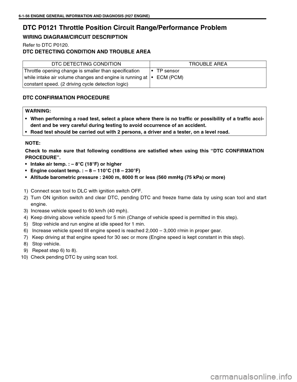
DTC P0121 Throttle Position Circuit Range/Performance Problem
WIRING DIAGRAM/CIRCUIT DESCRIPTION
Refer to DTC P0120.
DTC DETECTING CONDITION AND TROUBLE AREA
DTC CONFIRMATION PROCEDURE
1) Connect scan tool to DLC with ignition switch OFF.
2) Turn ON ignition switch and clear DTC, pending DTC and freeze frame data by using scan tool and start
engine.
3) Increase vehicle speed to 60 km/h (40 mph).
4) Keep driving above vehicle speed for 5 min (Change of vehicle speed is permitted in this step).
5) Stop vehicle and run engine at idle speed for 1 min.
6) Increase vehicle speed till engine speed is reached 2,000 – 3,000 r/min in proper gear.
7) Keep driving at that engine speed for 30 sec or more (Engine speed is kept constant in this step).
8) Stop vehicle.
9) Repeat step 6) to 8).
10) Check pending DTC by using scan tool.DTC DETECTING CONDITION TROUBLE AREA
Throttle opening change is smaller than specification
while intake air volume changes and engine is running at
constant speed. (2 driving cycle detection logic)•TP sensor
•ECM (PCM)
WARNING:
When performing a road test, select a place where there is no traffic or possibility of a traffic acci-
dent and be very careful during testing to avoid occurrence of an accident.
Road test should be carried out with 2 persons, a driver and a tester, on a level road.
NOTE:
Check to make sure that following conditions are satisfied when using this “DTC CONFIRMATION
PROCEDURE”.
Intake air temp. : – 8°C (18°F) or higher
Engine coolant temp. : – 8 – 110°C (18 – 230°F)
Altitude barometric pressure : 2400 m, 8000 ft or less (560 mmHg (75 kPa) or more)
Page 218 of 656
ENGINE GENERAL INFORMATION AND DIAGNOSIS (H27 ENGINE) 6-1-57
TROUBLESHOOTING
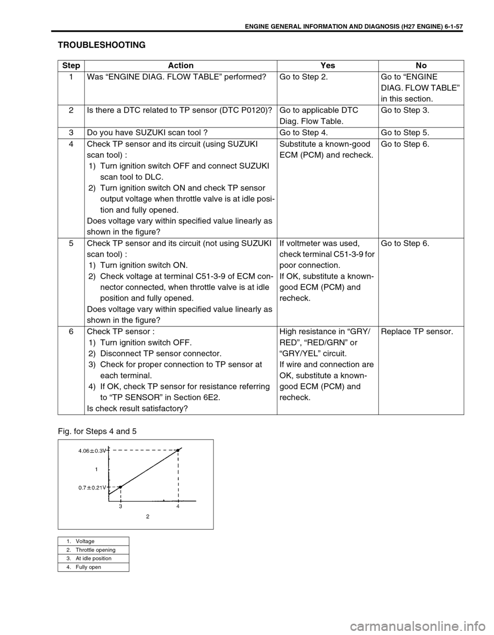
Fig. for Steps 4 and 5Step Action Yes No
1 Was “ENGINE DIAG. FLOW TABLE” performed? Go to Step 2. Go to “ENGINE
DIAG. FLOW TABLE”
in this section.
2 Is there a DTC related to TP sensor (DTC P0120)? Go to applicable DTC
Diag. Flow Table.Go to Step 3.
3 Do you have SUZUKI scan tool ? Go to Step 4. Go to Step 5.
4 Check TP sensor and its circuit (using SUZUKI
scan tool) :
1) Turn ignition switch OFF and connect SUZUKI
scan tool to DLC.
2) Turn ignition switch ON and check TP sensor
output voltage when throttle valve is at idle posi-
tion and fully opened.
Does voltage vary within specified value linearly as
shown in the figure?Substitute a known-good
ECM (PCM) and recheck.Go to Step 6.
5 Check TP sensor and its circuit (not using SUZUKI
scan tool) :
1) Turn ignition switch ON.
2) Check voltage at terminal C51-3-9 of ECM con-
nector connected, when throttle valve is at idle
position and fully opened.
Does voltage vary within specified value linearly as
shown in the figure?If voltmeter was used,
check terminal C51-3-9 for
poor connection.
If OK, substitute a known-
good ECM (PCM) and
recheck.Go to Step 6.
6 Check TP sensor :
1) Turn ignition switch OFF.
2) Disconnect TP sensor connector.
3) Check for proper connection to TP sensor at
each terminal.
4) If OK, check TP sensor for resistance referring
to “TP SENSOR” in Section 6E2.
Is check result satisfactory?High resistance in “GRY/
RED”, “RED/GRN” or
“GRY/YEL” circuit.
If wire and connection are
OK, substitute a known-
good ECM (PCM) and
recheck.Replace TP sensor.
1. Voltage
2. Throttle opening
3. At idle position
4. Fully open
Page 251 of 656
6-1-90 ENGINE GENERAL INFORMATION AND DIAGNOSIS (H27 ENGINE)
DTC DETECTING CONDITION AND TROUBLE AREA
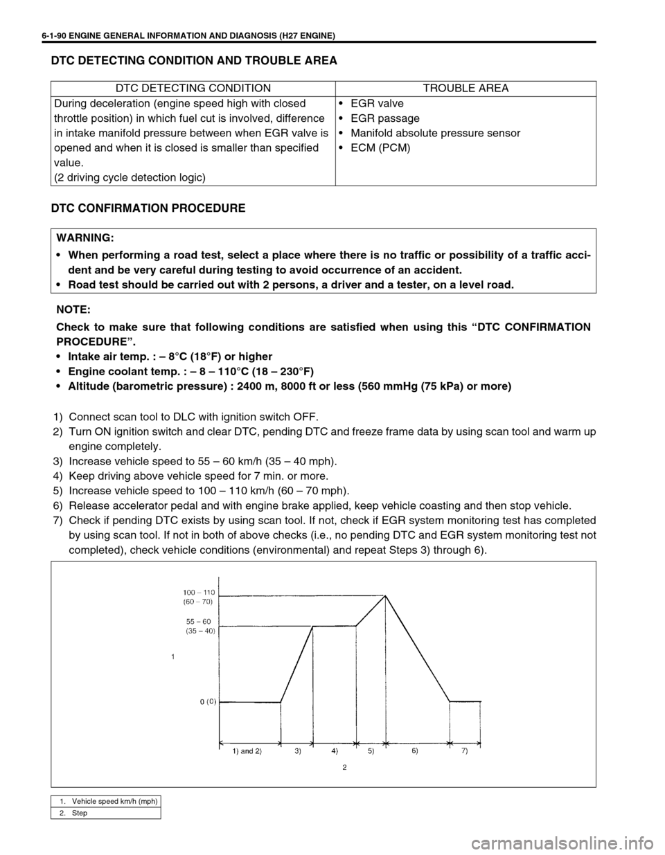
DTC CONFIRMATION PROCEDURE
1) Connect scan tool to DLC with ignition switch OFF.
2) Turn ON ignition switch and clear DTC, pending DTC and freeze frame data by using scan tool and warm up
engine completely.
3) Increase vehicle speed to 55 – 60 km/h (35 – 40 mph).
4) Keep driving above vehicle speed for 7 min. or more.
5) Increase vehicle speed to 100 – 110 km/h (60 – 70 mph).
6) Release accelerator pedal and with engine brake applied, keep vehicle coasting and then stop vehicle.
7) Check if pending DTC exists by using scan tool. If not, check if EGR system monitoring test has completed
by using scan tool. If not in both of above checks (i.e., no pending DTC and EGR system monitoring test not
completed), check vehicle conditions (environmental) and repeat Steps 3) through 6).DTC DETECTING CONDITION TROUBLE AREA
During deceleration (engine speed high with closed
throttle position) in which fuel cut is involved, difference
in intake manifold pressure between when EGR valve is
opened and when it is closed is smaller than specified
value.
(2 driving cycle detection logic)•EGR valve
• EGR passage
• Manifold absolute pressure sensor
•ECM (PCM)
WARNING:
When performing a road test, select a place where there is no traffic or possibility of a traffic acci-
dent and be very careful during testing to avoid occurrence of an accident.
Road test should be carried out with 2 persons, a driver and a tester, on a level road.
NOTE:
Check to make sure that following conditions are satisfied when using this “DTC CONFIRMATION
PROCEDURE”.
Intake air temp. : – 8°C (18°F) or higher
Engine coolant temp. : – 8 – 110°C (18 – 230°F)
Altitude (barometric pressure) : 2400 m, 8000 ft or less (560 mmHg (75 kPa) or more)
1. Vehicle speed km/h (mph)
2. Step
Page 256 of 656
ENGINE GENERAL INFORMATION AND DIAGNOSIS (H27 ENGINE) 6-1-95
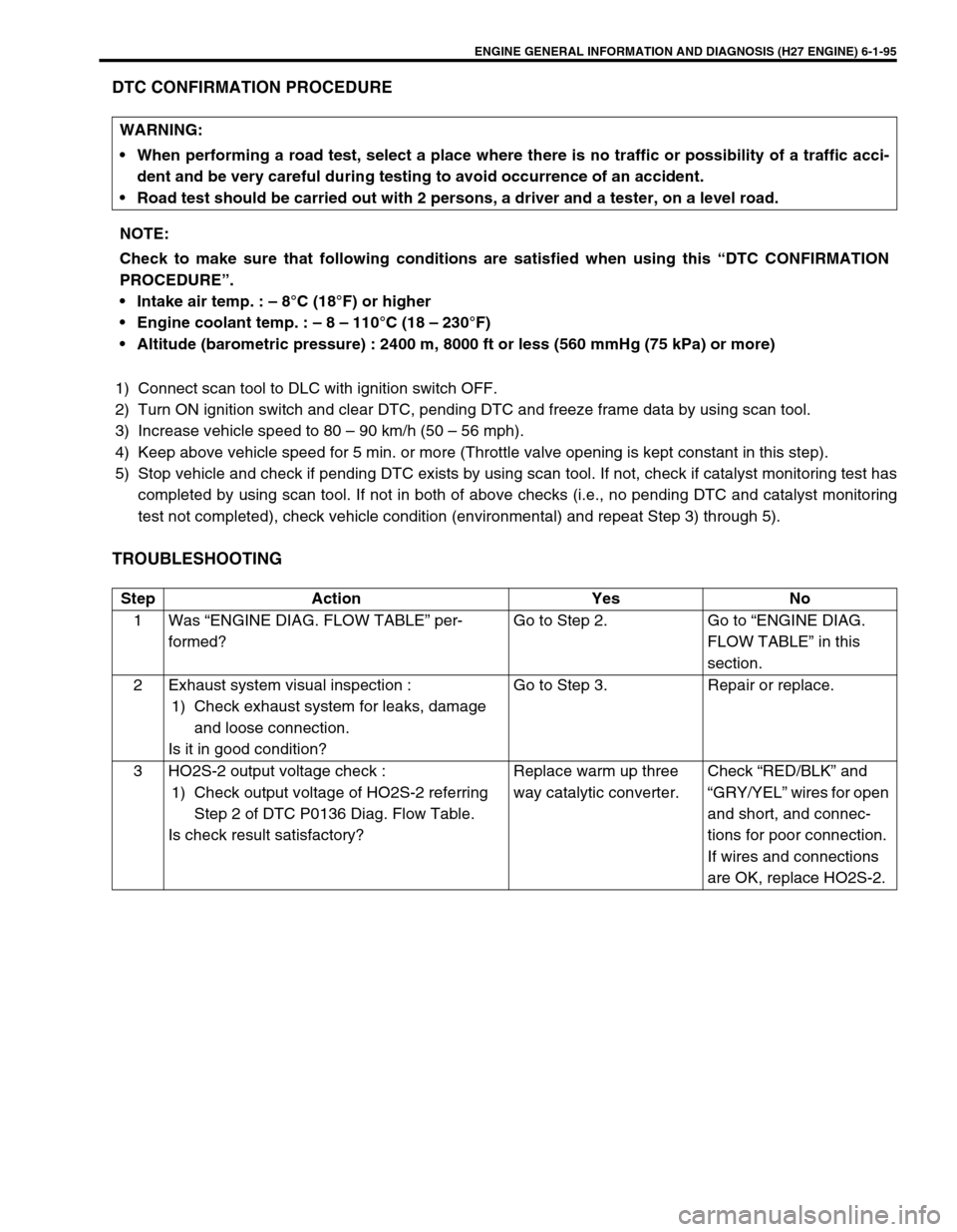
DTC CONFIRMATION PROCEDURE
1) Connect scan tool to DLC with ignition switch OFF.
2) Turn ON ignition switch and clear DTC, pending DTC and freeze frame data by using scan tool.
3) Increase vehicle speed to 80 – 90 km/h (50 – 56 mph).
4) Keep above vehicle speed for 5 min. or more (Throttle valve opening is kept constant in this step).
5) Stop vehicle and check if pending DTC exists by using scan tool. If not, check if catalyst monitoring test has
completed by using scan tool. If not in both of above checks (i.e., no pending DTC and catalyst monitoring
test not completed), check vehicle condition (environmental) and repeat Step 3) through 5).
TROUBLESHOOTING
WARNING:
When performing a road test, select a place where there is no traffic or possibility of a traffic acci-
dent and be very careful during testing to avoid occurrence of an accident.
Road test should be carried out with 2 persons, a driver and a tester, on a level road.
NOTE:
Check to make sure that following conditions are satisfied when using this “DTC CONFIRMATION
PROCEDURE”.
Intake air temp. : – 8°C (18°F) or higher
Engine coolant temp. : – 8 – 110°C (18 – 230°F)
Altitude (barometric pressure) : 2400 m, 8000 ft or less (560 mmHg (75 kPa) or more)
Step Action Yes No
1 Was “ENGINE DIAG. FLOW TABLE” per-
formed?Go to Step 2. Go to “ENGINE DIAG.
FLOW TABLE” in this
section.
2 Exhaust system visual inspection :
1) Check exhaust system for leaks, damage
and loose connection.
Is it in good condition?Go to Step 3. Repair or replace.
3 HO2S-2 output voltage check :
1) Check output voltage of HO2S-2 referring
Step 2 of DTC P0136 Diag. Flow Table.
Is check result satisfactory?Replace warm up three
way catalytic converter.Check “RED/BLK” and
“GRY/YEL” wires for open
and short, and connec-
tions for poor connection.
If wires and connections
are OK, replace HO2S-2.