SUZUKI GRAND VITARA 1999 2.G Owners Manual
Manufacturer: SUZUKI, Model Year: 1999, Model line: GRAND VITARA, Model: SUZUKI GRAND VITARA 1999 2.GPages: 656, PDF Size: 14.31 MB
Page 631 of 656
10B-54 AIR BAG SYSTEM
DEPLOYED AIR BAG (INFLATOR) MODULE AND ACTI-
VATED SEAT BELT PRETENSIONER
Refer to the procedure described under “DEPLOYED AIR BAG
(INFLATOR) MODULE AND ACTIVATED SEAT BELT PRETEN-
SIONER DISPOSAL” in this section for disposal. WARNING:
For handling and storage of a live seat belt preten-
sioner, select a place where the ambient temperature
below 65°
°° °C (150°
°° °F), without high humidity and away
from electric noise.
Never carry the seat belt pretensioner by the wire or
connector of the pretensioner.
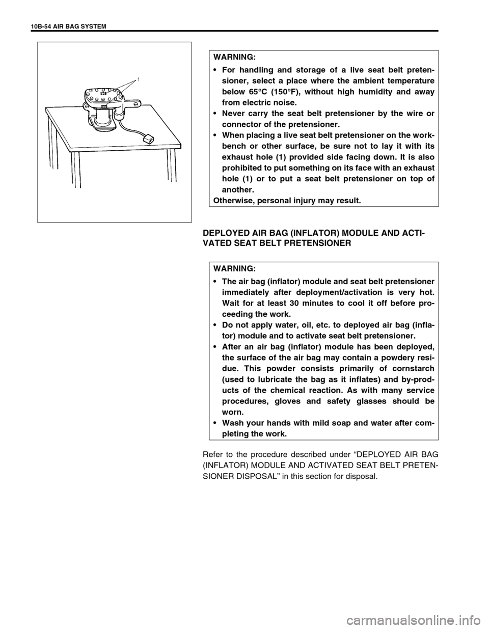
When placing a live seat belt pretensioner on the work-
bench or other surface, be sure not to lay it with its
exhaust hole (1) provided side facing down. It is also
prohibited to put something on its face with an exhaust
hole (1) or to put a seat belt pretensioner on top of
another.
Otherwise, personal injury may result.
WARNING:
The air bag (inflator) module and seat belt pretensioner
immediately after deployment/activation is very hot.
Wait for at least 30 minutes to cool it off before pro-
ceeding the work.
Do not apply water, oil, etc. to deployed air bag (infla-
tor) module and to activate seat belt pretensioner.
After an air bag (inflator) module has been deployed,
the surface of the air bag may contain a powdery resi-
due. This powder consists primarily of cornstarch
(used to lubricate the bag as it inflates) and by-prod-
ucts of the chemical reaction. As with many service
procedures, gloves and safety glasses should be
worn.
Wash your hands with mild soap and water after com-
pleting the work.
Page 632 of 656
AIR BAG SYSTEM 10B-55
AIR BAG WIRE HARNESS AND CONNECTOR
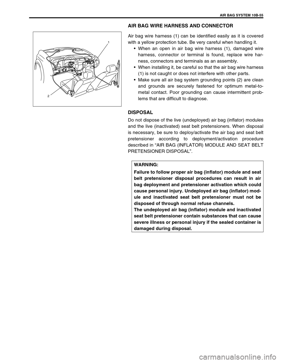
Air bag wire harness (1) can be identified easily as it is covered
with a yellow protection tube. Be very careful when handling it.
•When an open in air bag wire harness (1), damaged wire
harness, connector or terminal is found, replace wire har-
ness, connectors and terminals as an assembly.
•When installing it, be careful so that the air bag wire harness
(1) is not caught or does not interfere with other parts.
•Make sure all air bag system grounding points (2) are clean
and grounds are securely fastened for optimum metal-to-
metal contact. Poor grounding can cause intermittent prob-
lems that are difficult to diagnose.
DISPOSAL
Do not dispose of the live (undeployed) air bag (inflator) modules
and the live (inactivated) seat belt pretensioners. When disposal
is necessary, be sure to deploy/activate the air bag and seat belt
pretensioner according to deployment/activation procedure
described in “AIR BAG (INFLATOR) MODULE AND SEAT BELT
PRETENSIONER DISPOSAL”.
15
21
WARNING:
Failure to follow proper air bag (inflator) module and seat
belt pretensioner disposal procedures can result in air
bag deployment and pretensioner activation which could
cause personal injury. Undeployed air bag (inflator) mod-
ule and inactivated seat belt pretensioner must not be
disposed of through normal refuse channels.
The undeployed air bag (inflator) module and inactivated
seat belt pretensioner contain substances that can cause
severe illness or personal injury if the sealed container is
damaged during disposal.
Page 633 of 656
10B-56 AIR BAG SYSTEM
Repairs and Inspections Required after an Accident
Accident with deployment/activation - component replacement
Certain air bag system components must be replaced. Those components are:
•Driver and passenger air bag (inflator) modules
–Replace with new one.
•Driver and Passenger seat belt pretensioners
–Replace with new one.
•SDM after detecting such collision as to meet deployment conditions
–Replace with new one.
•Forward sensors
–Replace with new one. CAUTION:
All air bag system components, including the electrical harness (component mounting points),
must be inspected after an accident. If any components are damaged or bent, they must be replaced
even if air bag system activation did not occur.
Never use air bag system parts from another vehicle.
Do not attempt to service the parts below. Service of these parts is by replacement only.
–Driver/Passenger air bag (inflator) modules, Driver/Passenger seat belt pretensioners
–Forward sensors
–SDM
–Contact coil and combination switch assembly
–Air bag wire harness
Proper operation of the sensors and air bag system requires that any repairs to the vehicle struc-
ture return it to its original production configuration.
CAUTION:
After detecting one time of such collision as to meet deployment conditions, the SDM must not be
used.
Refer to “AIR BAG DIAGNOSTIC SYSTEM CHECK” when checking the SDM.
Page 634 of 656
AIR BAG SYSTEM 10B-57
Accident with or without deployment/activation - component inspections
Certain air bag and restraint system components must be inspected after any crash, whether the air bag system
activated or not.
Those components are:
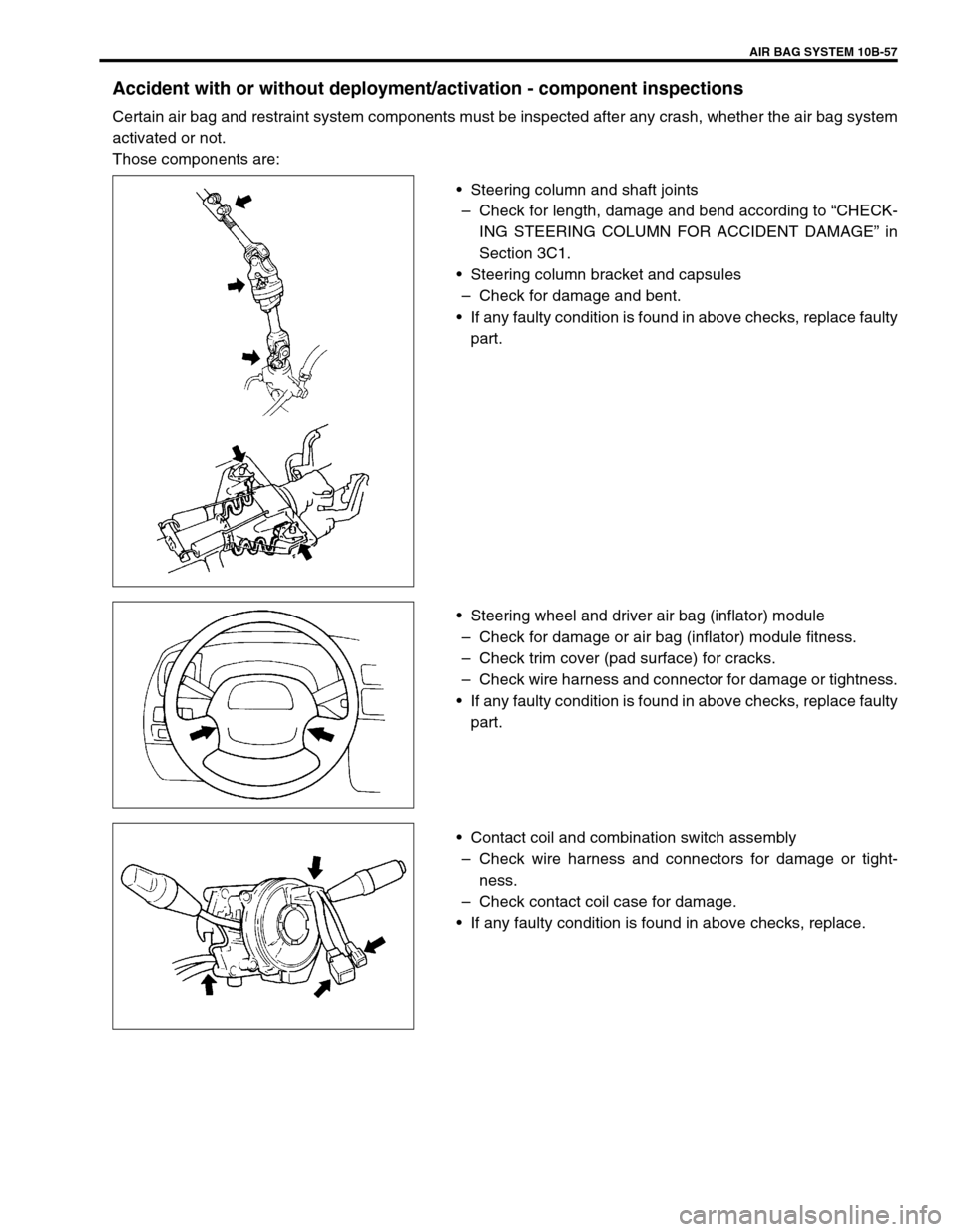
•Steering column and shaft joints
–Check for length, damage and bend according to “CHECK-
ING STEERING COLUMN FOR ACCIDENT DAMAGE” in
Section 3C1.
•Steering column bracket and capsules
–Check for damage and bent.
•If any faulty condition is found in above checks, replace faulty
part.
•Steering wheel and driver air bag (inflator) module
–Check for damage or air bag (inflator) module fitness.
–Check trim cover (pad surface) for cracks.
–Check wire harness and connector for damage or tightness.
•If any faulty condition is found in above checks, replace faulty
part.
•Contact coil and combination switch assembly
–Check wire harness and connectors for damage or tight-
ness.
–Check contact coil case for damage.
•If any faulty condition is found in above checks, replace.
Page 635 of 656
10B-58 AIR BAG SYSTEM
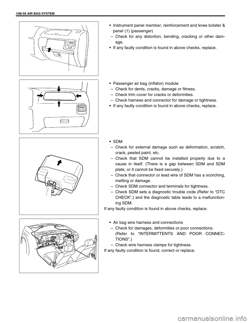
•Instrument panel member, reinforcement and knee bolster &
panel (1) (passenger)
–Check for any distortion, bending, cracking or other dam-
age.
•If any faulty condition is found in above checks, replace.
•Passenger air bag (inflator) module
–Check for dents, cracks, damage or fitness.
–Check trim cover for cracks or deformities.
–Check harness and connector for damage or tightness.
•If any faulty condition is found in above checks, replace.
•SDM
–Check for external damage such as deformation, scratch,
crack, peeled paint, etc.
–Check that SDM cannot be installed properly due to a
cause in itself. (There is a gap between SDM and SDM
plate, or it cannot be fixed securely.)
–Check that connector or lead wire of SDM has a scorching,
melting or damage.
–Check SDM connector and terminals for tightness.
–Check SDM sets a diagnostic trouble code (Refer to “DTC
CHECK”.) and the diagnostic table leads to a malfunction-
ing SDM.
If any faulty condition is found in above checks, replace.
•Air bag wire harness and connections
–Check for damages, deformities or poor connections.
(Refer to “INTERMITTENTS AND POOR CONNEC-
TIONS”.)
–Check wire harness clamps for tightness.
If any faulty condition is found, correct or replace.
15
Page 636 of 656
AIR BAG SYSTEM 10B-59
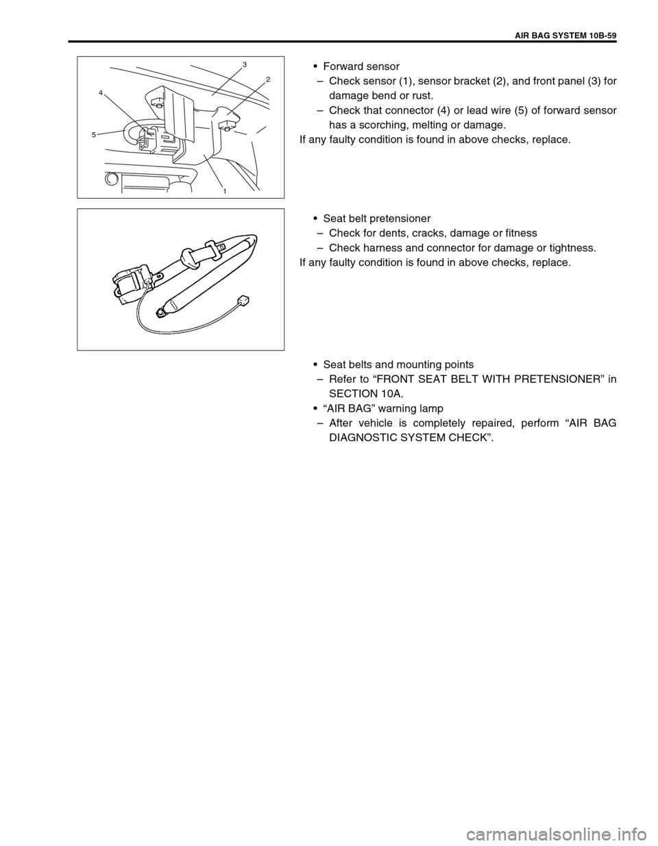
•Forward sensor
–Check sensor (1), sensor bracket (2), and front panel (3) for
damage bend or rust.
–Check that connector (4) or lead wire (5) of forward sensor
has a scorching, melting or damage.
If any faulty condition is found in above checks, replace.
•Seat belt pretensioner
–Check for dents, cracks, damage or fitness
–Check harness and connector for damage or tightness.
If any faulty condition is found in above checks, replace.
•Seat belts and mounting points
–Refer to “FRONT SEAT BELT WITH PRETENSIONER” in
SECTION 10A.
•“AIR BAG” warning lamp
–After vehicle is completely repaired, perform “AIR BAG
DIAGNOSTIC SYSTEM CHECK”.
543
2
1
Page 637 of 656
10B-60 AIR BAG SYSTEM
SDM
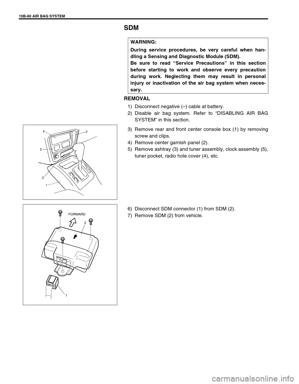
REMOVAL
1) Disconnect negative (–) cable at battery.
2) Disable air bag system. Refer to “DISABLING AIR BAG
SYSTEM” in this section.
3) Remove rear and front center console box (1) by removing
screw and clips.
4) Remove center garnish panel (2).
5) Remove ashtray (3) and tuner assembly, clock assembly (5),
tuner pocket, radio hole cover (4), etc.
6) Disconnect SDM connector (1) from SDM (2).
7) Remove SDM (2) from vehicle.WARNING:
During service procedures, be very careful when han-
dling a Sensing and Diagnostic Module (SDM).
Be sure to read “Service Precautions” in this section
before starting to work and observe every precaution
during work. Neglecting them may result in personal
injury or inactivation of the air bag system when neces-
sary.
2
1FORWARD
Page 638 of 656
AIR BAG SYSTEM 10B-61
INSPECTION
•Check SDM and SDM plate for dents, cracks or deformation.
•Check SDM connector for damage, cracks or lock mecha-
nism.
•Check SDM terminal for bent, corrosion or rust.
If any faulty condition is found in above checks, replace.
INSTALLATION
1) Check that none of following faulty conditions exists.
•Bend, scratch, deformity in vehicle body mounted on SDM
•Foreign matter or rust on mating surface of vehicle body
mounted on SDM
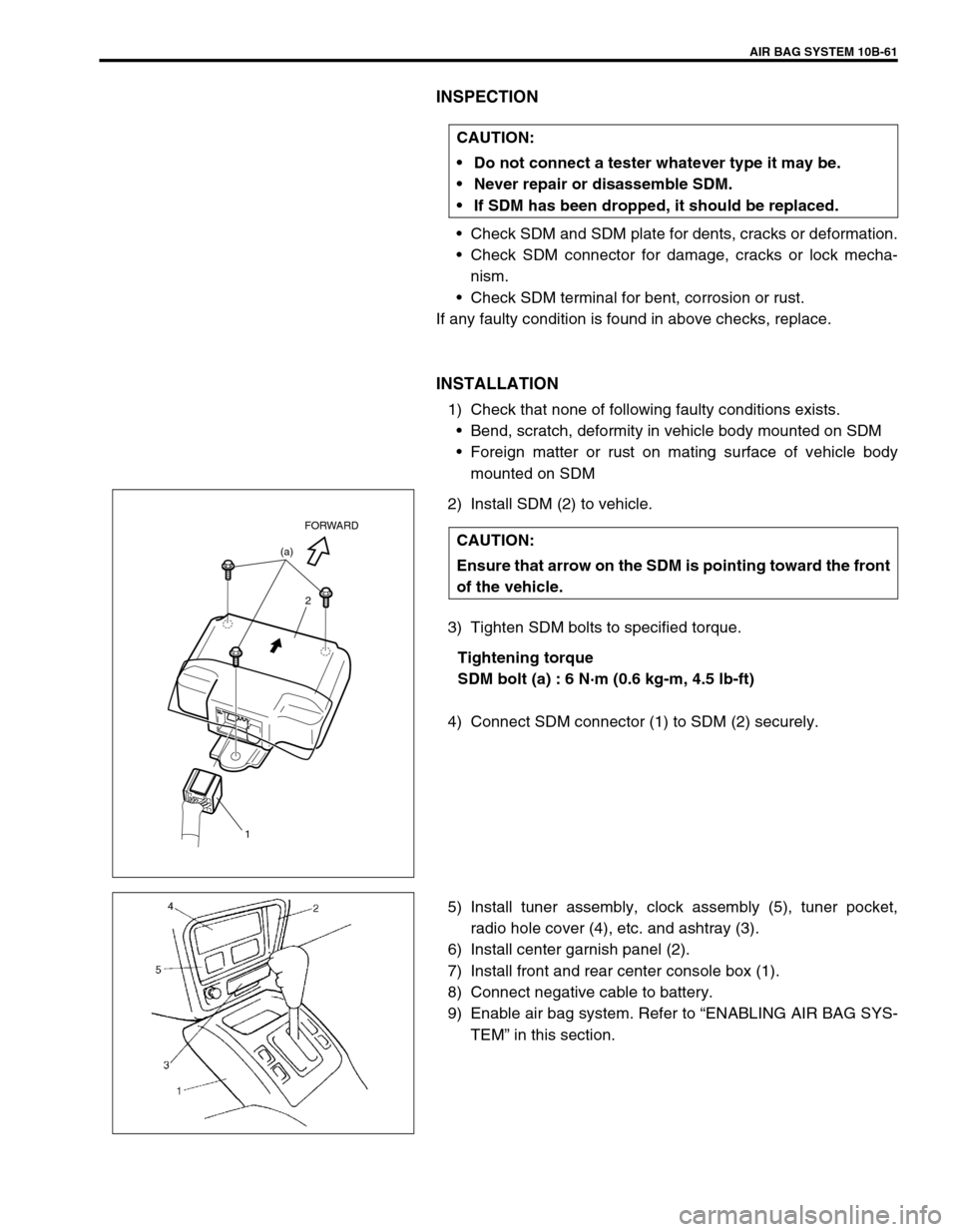
2) Install SDM (2) to vehicle.
3) Tighten SDM bolts to specified torque.
Tightening torque
SDM bolt (a) : 6 N·m (0.6 kg-m, 4.5 lb-ft)
4) Connect SDM connector (1) to SDM (2) securely.
5) Install tuner assembly, clock assembly (5), tuner pocket,
radio hole cover (4), etc. and ashtray (3).
6) Install center garnish panel (2).
7) Install front and rear center console box (1).
8) Connect negative cable to battery.
9) Enable air bag system. Refer to “ENABLING AIR BAG SYS-
TEM” in this section. CAUTION:
Do not connect a tester whatever type it may be.
Never repair or disassemble SDM.
If SDM has been dropped, it should be replaced.
CAUTION:
Ensure that arrow on the SDM is pointing toward the front
of the vehicle.(a)
2
1
FORWARD
Page 639 of 656
10B-62 AIR BAG SYSTEM
Forward Sensor
REMOVAL
1) Disconnect negative cable at battery.
2) Disable air bag system. Refer to “DISABLING AIR BAG
SYSTEM” in this section.
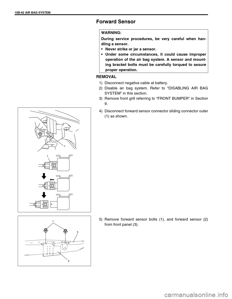
3) Remove front grill referring to “FRONT BUMPER” in Section
9.
4) Disconnect forward sensor connector sliding connector outer
(1) as shown.
5) Remove forward sensor bolts (1), and forward sensor (2)
from front panel (3). WARNING:
During service procedures, be very careful when han-
dling a sensor.
Never strike or jar a sensor.
Under some circumstances, it could cause improper
operation of the air bag system. A sensor and mount-
ing bracket bolts must be carefully torqued to assure
proper operation.
1
1
1
3
2
Page 640 of 656
AIR BAG SYSTEM 10B-63
INSPECTION
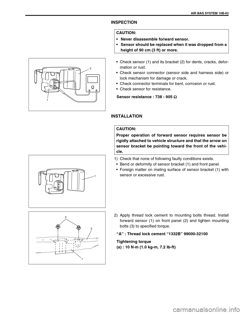
•Check sensor (1) and its bracket (2) for dents, cracks, defor-
mation or rust.
•Check sensor connector (sensor side and harness side) or
lock mechanism for damage or crack.
•Check connector terminals for bent, corrosion or rust.
•Check sensor for resistance.
Sensor resistance : 738 - 905 Ω
ΩΩ Ω
INSTALLATION
1) Check that none of following faulty conditions exists.
•Bend or deformity of sensor bracket (1) and front panel.
•Foreign matter on mating surface of sensor bracket (1) with
sensor or excessive rust.
2) Apply thread lock cement to mounting bolts thread. Install
forward sensor (1) on front panel (2) and tighten mounting
bolts (3) to specified torque.
“A” : Thread lock cement “1332B” 99000-32100
Tightening torque
(a) : 10 N·m (1.0 kg-m, 7.2 lb-ft) CAUTION:
Never disassemble forward sensor.
Sensor should be replaced when it was dropped from a
height of 90 cm (3 ft) or more.
2
1
CAUTION:
Proper operation of forward sensor requires sensor be
rigidly attached to vehicle structure and that the arrow on
sensor bracket be pointing toward the front of the vehi-
cle.
1
3
2
1