Head SUZUKI GRAND VITARA 2000 2.G Service Service Manual
[x] Cancel search | Manufacturer: SUZUKI, Model Year: 2000, Model line: GRAND VITARA, Model: SUZUKI GRAND VITARA 2000 2.GPages: 801, PDF Size: 12.15 MB
Page 647 of 801

YH4
GRAND
VITARA
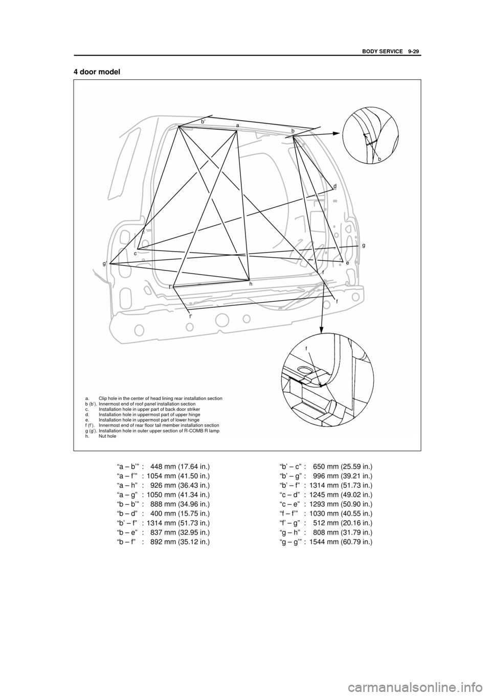
ªa ± b'º : 448 mm (17.64 in.)
ªa ± f'º : 1054 mm (41.50 in.)
ªa ± hº : 926 mm (36.43 in.)
ªa ± gº : 1050 mm (41.34 in.)
ªb ± b'º : 888 mm (34.96 in.)
ªb ± dº : 400 mm (15.75 in.)
ªb' ± fº : 1314 mm (51.73 in.)
ªb ± eº : 837 mm (32.95 in.)
ªb ± fº : 892 mm (35.12 in.)ªb' ± cº : 650 mm (25.59 in.)
ªb' ± gº : 996 mm (39.21 in.)
ªb' ± fº : 1314 mm (51.73 in.)
ªc ± dº : 1245 mm (49.02 in.)
ªc ± eº : 1293 mm (50.90 in.)
ªf ± f'º : 1030 mm (40.55 in.)
ªf' ± gº : 512 mm (20.16 in.)
ªg ± hº : 808 mm (31.79 in.)
ªg ± g'º : 1544 mm (60.79 in.)
a. Clip hole in the center of head lining rear installation section
b (b'). Innermost end of roof panel installation section
c. Installation hole in upper part of back door striker
d. Installation hole in uppermost part of upper hinge
e. Installation hole in uppermost part of lower hinge
f (f'). Innermost end of rear floor tail member installation section
g (g'). Installation hole in outer upper section of R-COMB R lamp
h. Nut hole
BODY SERVICE 9-29
4 door model
Page 684 of 801

YH4
GRAND
VITARA
1. Spot light
2. Head lining
3. Sunvisor assemblies
4. Room light
5. Trim
6. Assist grips
1. Sliding roof motor
2. Mounting screw
1. Motor assy
2. Hole (body)
3. Hole (cam)
9-66 BODY SERVICE
SLIDING ROOF MOTOR / RELAY
REMOVAL
1) Remove head lining, refer to HEAD LINING REMOVAL in this
section.
2) Disconnect coupler and remove sliding roof motor assembly by
removing 3 screws.
CAUTION:
After removing sliding motor assembly, do not move
guide and link.
INSTALLATION
For installation, reverse removal procedure, noting following point.
Before installing, connect coupler and push the CLOSE side of the
slide switch.
Page 685 of 801

YH4
GRAND
VITARA
BODY SERVICE 9-67
1. Drain hoses
1. Sliding roof motor
2. Coupler
1. Sliding roof assembly fixing nuts
2. Sliding roof assembly
SLIDING ROOF ASSEMBLY
REMOVAL
1) Remove roof lining. Refer to HEAD LINING REMOVAL in this
section.
2) Remove sliding roof glass. Refer to SLIDING ROOF GLASS
REMOVAL.
3) Disconnect drain hoses connected to sliding roof assembly at 4
locations.
4) Disconnect sliding roof motor at coupler.
5) Remove 6 nuts and then remove sliding roof assembly.
Page 691 of 801

YH4
GRAND
VITARA
BODY SERVICE 9-73
5
46
4. Assistant grip
5. Rear room light
6. Inner trim
1. Roof harness
2. Rear washer hose
3. Adhesive tape
Front 1. Room light
2. Sunshade assembly
3. Spot light
IWATA
CAMI
HEAD LINING
REMOVAL
1) Remove spot light and sliding roof switch (if equipped).
2) Remove sunshade assembly.
3) Remove room light and spacer.
4) Remove assistant grips.
5) Remove inner trims covering head lining and door opening trim.
6) Remove rear speaker cover (if equipped).
7) Disconnect rear washer hose and roof harness from body.
8) Remove head lining.
NOTE:
Adhesive double coated tape is used to attach rear part of
head lining. Detach head lining from roof after removing all
above parts.
INSTALLATION
1) Set roof harness and washer hose to head lining with tape.
2) Clean roof where adhesive tape of head lining will be attached.
3) Peel off release liner of adhesive tape on head lining and install
it to body.
4) Install assistant grips a, b, c and d in that order.
Page 692 of 801

YH4
GRAND
VITARA
9-74 BODY SERVICE
1. Door opening trim
2. Head liningSetSet
4. Assistant grip
5. Rear room light
6. Inner trim 1. Room light
2. Sunshade assembly
3. Spot light
IWATA
CAMI
5) Install door opening trim.
6) Install spot light, sunshade assembly, speaker cover, room light
and inner trims covering head lining.
Page 698 of 801

YH4
GRAND
VITARA
9-80 BODY SERVICE
1. Bolt
2. Member
LUGGAGE UNDER BOX
WARNING:
Do not remove member in the center of luggage under box.
If member had to be removed temporarily for repair or for some oth-
er reason, be sure to reinstall it by using specified new bolts until
head of bolt is broken off.
Page 762 of 801

YH4
GRAND
VITARA
1. Air bag harness
2. ªAIR BAGº monitor coupler
3. Yellow connector of contact coil and combination
switch assembly
4. Yellow connector of passenger air bag (inflator) module
5. Steering support member
1. Air bag harness
2. ªAIR BAGº monitor coupler
3. Yellow connector of contact coil and combination
switch assembly
10B-56 AIR BAG SYSTEM
DISABLING AIR BAG SYSTEM
1) Turn steering wheel so that vehicle's wheels (front tires) and
pointing straight ahead.
2) Turn ignition switch to ªLOCKº position and remove key.
3) Remove ªAIR BAGº fuse from ªAIR BAGº fuse box.
4) Disconnect Yellow connector of contact coil and combination
switch assembly.
ii) Release locking of lock lever.
ii) After unlocked, disconnect to connector.
5) Pull out glove box while pushing its stopper from both right and
left sides and disconnect Yellow connector of passenger air bag
(inflator) module.
ii) Release locking of lock lever.
ii) After unlocked, disconnect to connector.
NOTE:
With ªAIR BAGº fuse removed and ignition switch ON, ªAIR
BAGº warning lamp will be ON.
This is normal operation and does not indicate an air bag
system malfunction.
ENABLING AIR BAG SYSTEM
1) Turn ignition switch to ªLOCKº and remove key.
2) Connect Yellow connector of contact coil and combination
switch assembly, and be sure to lock connector with lock lever.
ii) Connect connector.
ii) Lock connector with lock lever.