acc SUZUKI GRAND VITARA 2001 2.G User Guide
[x] Cancel search | Manufacturer: SUZUKI, Model Year: 2001, Model line: GRAND VITARA, Model: SUZUKI GRAND VITARA 2001 2.GPages: 656, PDF Size: 14.31 MB
Page 77 of 656
3C1-2 AIR BAG STEERING WHEEL AND COLUMN
General Description
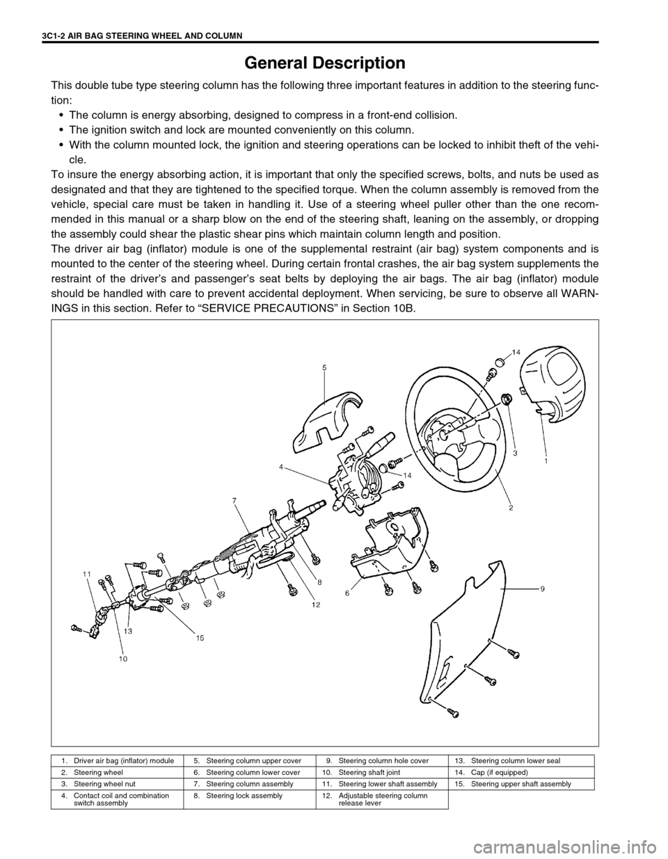
This double tube type steering column has the following three important features in addition to the steering func-
tion:
The column is energy absorbing, designed to compress in a front-end collision.
The ignition switch and lock are mounted conveniently on this column.
With the column mounted lock, the ignition and steering operations can be locked to inhibit theft of the vehi-
cle.
To insure the energy absorbing action, it is important that only the specified screws, bolts, and nuts be used as
designated and that they are tightened to the specified torque. When the column assembly is removed from the
vehicle, special care must be taken in handling it. Use of a steering wheel puller other than the one recom-
mended in this manual or a sharp blow on the end of the steering shaft, leaning on the assembly, or dropping
the assembly could shear the plastic shear pins which maintain column length and position.
The driver air bag (inflator) module is one of the supplemental restraint (air bag) system components and is
mounted to the center of the steering wheel. During certain frontal crashes, the air bag system supplements the
restraint of the driver’s and passenger’s seat belts by deploying the air bags. The air bag (inflator) module
should be handled with care to prevent accidental deployment. When servicing, be sure to observe all WARN-
INGS in this section. Refer to “SERVICE PRECAUTIONS” in Section 10B.
1. Driver air bag (inflator) module 5. Steering column upper cover 9. Steering column hole cover 13. Steering column lower seal
2. Steering wheel 6. Steering column lower cover 10. Steering shaft joint 14. Cap (if equipped)
3. Steering wheel nut 7. Steering column assembly 11. Steering lower shaft assembly 15. Steering upper shaft assembly
4. Contact coil and combination
switch assembly8. Steering lock assembly 12. Adjustable steering column
release lever
Page 78 of 656

AIR BAG STEERING WHEEL AND COLUMN 3C1-3
Diagnosis
For diagnosis of the steering wheel and steering column, refer to Section 3. For diagnosis of the air bag system,
refer to Section 10B.
Inspection and Repair Required after Accident
After an accident, whether the air bag has been deployed or not, be sure to perform checks, inspections and
repairs described under “CHECKING STEERING COLUMN FOR ACCIDENT DAMAGE” in this section as well
as “REPAIRS AND INSPECTIONS REQUIRED AFTER ACCIDENT” in Section 10B.
On-Vehicle Service
Service Precautions
For service precautions, refer to “SERVICE PRECAUTIONS” under “ON-VEHICLE SERVICE” in Section 10B.
Diagnosis and servicing
For diagnosis and servicing, refer to “DIAGNOSIS AND SERVICING” under “SERVICE PRECAUTIONS” in
Section 10B.
Disabling air bag system
For disabling air bag system, refer to “DISABLING AIR BAG SYSTEM” under “SERVICE PRECAUTIONS” in
Section 10B.
Enabling air bag system
For enabling air bag system, refer to “ENABLING AIR BAG SYSTEM” under “SERVICE PRECAUTIONS” in
Section 10B.
Handling and storage
For handling and storage, refer to “HANDLING AND STORAGE” under “SERVICE PRECAUTIONS” in Section
10B.
Disposal
For disposal, refer to “DISPOSAL” under “SERVICE PRECAUTIONS” in Section 10B.
Page 79 of 656

3C1-4 AIR BAG STEERING WHEEL AND COLUMN
Steering Column
REMOVAL
1) Disconnect negative (–) cable at battery.
2) Disable air bag system. Refer to “DISABLING AIR BAG SYSTEM” under “SERVICE PRECAUTIONS” in
Section 10B.
3) Remove steering wheel and contact coil and combination switch assembly, if necessary. Refer to “STEER-
ING WHEEL” and “CONTACT COIL AND COMBINATION SWITCH ASSEMBLY” in this section.
Perform the following procedure if not removing steering wheel and/or combination switch.
a) Turn steering wheel so that vehicle’s front tires are at straight-ahead position.
b) Turn ignition switch to “LOCK” position and remove key.
4) Remove steering column hole cover (1).
5) Disconnect all connectors for the following parts.
Contact coil and combination switch
Ignition switch CAUTION:
Once the steering column is removed from the vehicle, the column is extremely susceptible to dam-
age.
Dropping the column assembly on its end could collapse the steering shaft or loosen the plastic
shear pins which maintain column length leaning on the column assembly could cause it to bend or
deform.
Any of the above damage could impair the column’s collapsible design.
When loosening steering column mounting bolts and nuts, make sure that steering column assembly
and steering upper shaft assembly have been separated. Loosening them with steering column
assembly and steering upper shaft assembly assembled could cause damage to upper joint and
mounting bracket in steering upper shaft assembly.
NOTE:
When servicing steering column or any column-mounted component, remove steering wheel. But
when removing steering column simply to gain access to instrument panel components, leave steer-
ing wheel installed on steering column.
WARNING:
Never rest a steering column assembly on the steering wheel with air bag (inflator) module face down
and column vertical. Otherwise personal injury may result.
CAUTION:
Never turn steering wheel while steering column with steering wheel is removed. Turning steering
wheel more than about two and a half turns will break contact coil.
Page 80 of 656
AIR BAG STEERING WHEEL AND COLUMN 3C1-5
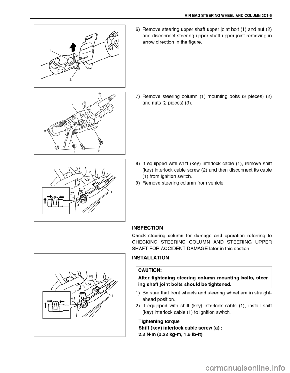
6) Remove steering upper shaft upper joint bolt (1) and nut (2)
and disconnect steering upper shaft upper joint removing in
arrow direction in the figure.
7) Remove steering column (1) mounting bolts (2 pieces) (2)
and nuts (2 pieces) (3).
8) If equipped with shift (key) interlock cable (1), remove shift
(key) interlock cable screw (2) and then disconnect its cable
(1) from ignition switch.
9) Remove steering column from vehicle.
INSPECTION
Check steering column for damage and operation referring to
CHECKING STEERING COLUMN AND STEERING UPPER
SHAFT FOR ACCIDENT DAMAGE later in this section.
INSTALLATION
1) Be sure that front wheels and steering wheel are in straight-
ahead position.
2) If equipped with shift (key) interlock cable (1), install shift
(key) interlock cable (1) to ignition switch.
Tightening torque
Shift (key) interlock cable screw (a) :
2.2 N·m (0.22 kg-m, 1.6 lb-ft)
1
2
1
32
CAUTION:
After tightening steering column mounting bolts, steer-
ing shaft joint bolts should be tightened.
Page 83 of 656
3C1-8 AIR BAG STEERING WHEEL AND COLUMN
INSPECTION
Check steering shaft damage and operation referring to CHECK
STEERING COLUMN AND STEERING UPPER SHAFT FOR
ACCIDENT DAMAGE later in this section.
INSTALLATION
1) Be sure that front tires and steering wheel are in straight
ahead position.
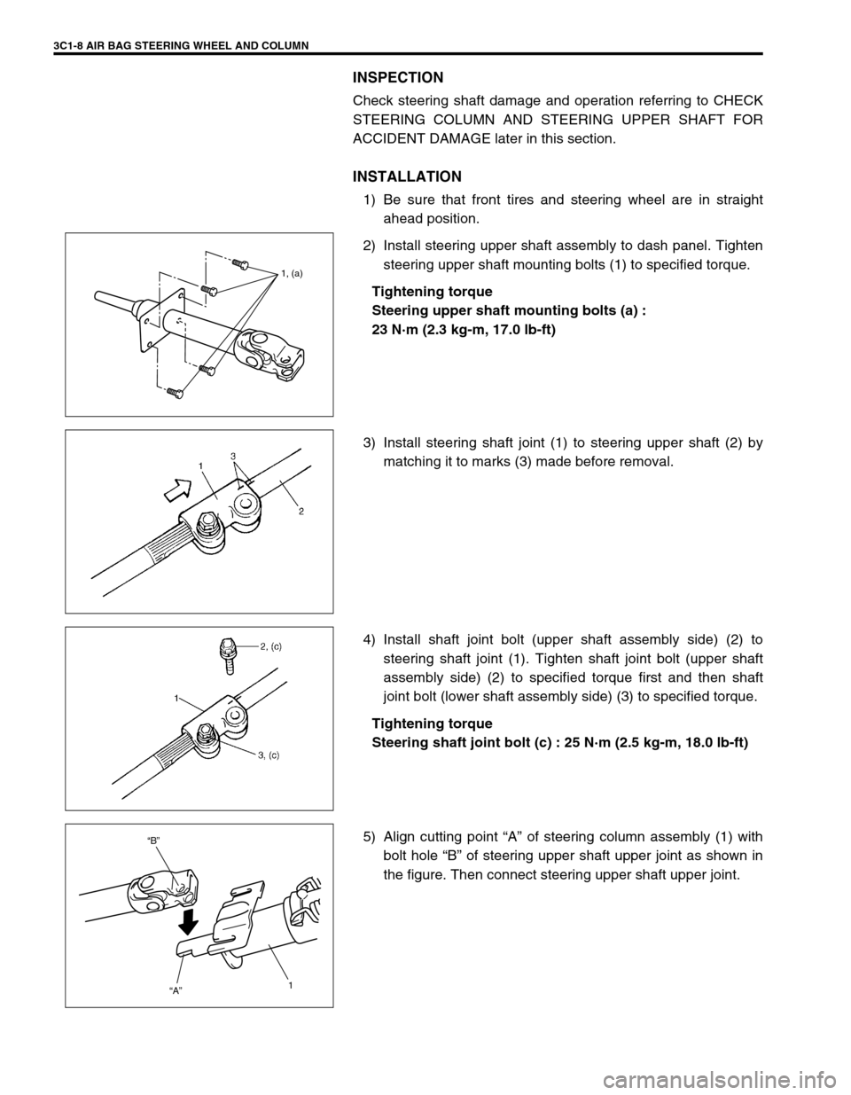
2) Install steering upper shaft assembly to dash panel. Tighten
steering upper shaft mounting bolts (1) to specified torque.
Tightening torque
Steering upper shaft mounting bolts (a) :
23 N·m (2.3 kg-m, 17.0 lb-ft)
3) Install steering shaft joint (1) to steering upper shaft (2) by
matching it to marks (3) made before removal.
4) Install shaft joint bolt (upper shaft assembly side) (2) to
steering shaft joint (1). Tighten shaft joint bolt (upper shaft
assembly side) (2) to specified torque first and then shaft
joint bolt (lower shaft assembly side) (3) to specified torque.
Tightening torque
Steering shaft joint bolt (c) : 25 N·m (2.5 kg-m, 18.0 lb-ft)
5) Align cutting point “A” of steering column assembly (1) with
bolt hole “B” of steering upper shaft upper joint as shown in
the figure. Then connect steering upper shaft upper joint.
1, (a)
“B”
“A”
1
Page 86 of 656

AIR BAG STEERING WHEEL AND COLUMN 3C1-11
Checking Steering Column and Steering
Upper Shaft for Accident Damage
Check that 2 capsules are attached to steering column
bracket securely. Check clearance between capsules and
steering column bracket. Clearance should be 0 mm (0 in.)
on both sides. If found loose or clearance, replace steering
column assembly.
Take measurement “a” as shown in the figure. If it is shorter
than specified length, replace column assembly with new
one.
Steering column assembly length “a” :
490.3 ± 1.0 mm (19.30 ± 0.04 in.)
Check steering shaft for smooth rotation.
If found defective, replace as column assembly.
Check steering shaft and column for bend, cracks or defor-
mation.
If found defective, replace as column assembly.
Check steering upper shaft lower seal (1) for breakage or
deformation.
If found defective, replace.
Check steering shaft joints and shaft for any damages such
as crack, breakage, malfunction or excessive play.
If anything is found faulty, replace steering upper shaft
assembly, steering lower shaft assembly or steering column
assembly. NOTE:
Vehicles involved in accidents resulting in body damage,
where steering column has been impacted or air bag
deployed, may have a damaged or misaligned steering
column.
1. Capsule
2. Steering column bracket
1
2
“a”
Page 90 of 656
REAR SUSPENSION 3E-1
3E
SECTION 3E
REAR SUSPENSION
CONTENTS
On-Vehicle Service......................................... 3E-1
Rear Axle Shaft and Wheel Bearing ............ 3E-1
Rear Axle Shaft Inner Oil Seal ..................... 3E-5
Rear Axle Housing ....................................... 3E-5Tightening Torque Specification .................. 3E-6
Required Service Material ............................. 3E-6
Special Tool .................................................... 3E-7
On-Vehicle Service
Rear Axle Shaft and Wheel Bearing
REMOVAL
1) Remove axle shaft from axle housing according to Step1) to
6) in the same section in the service manual mentioned in
the FOREWORD of this manual noting following points. NOTE:
For the descriptions (items) not found in this section, refer to the same section of the Service Man-
ual mentioned in the FOREWORD of this manual.
All suspension fasteners are an important attaching part in that it could affect the performance of
vital parts and systems, and/or could result in major repair expense. They must be replaced with
one of the same part number or with an equivalent part if replacement becomes necessary. Do not
use a replacement part of lesser quality or substitute design. Torque values must be used as speci-
fied during reassembly to assure proper retention of this part.
Never attempt to heat, quench or straighten any suspension part. Replace it with a new part, or
damage to the part may result.
Page 98 of 656

WHEELS AND TIRES 3F-1
3F
SECTION 3F
WHEELS AND TIRES
CONTENTS
General Description ....................................... 3F-1
Tires ............................................................. 3F-1
Wheels ......................................................... 3F-1
General Description
Tires
This vehicle is equipped with following tire.
Tire specification :
P235/60 R16 or 235/60 R16
The tires are of tubeless type. The tires are designed to operate satisfactorily with loads up to the full rated load
capacity when inflated to the recommended inflation pressure.
Correct tire pressures and driving habits have an important influence on tire life. Heavy cornering, excessively
rapid acceleration, and unnecessary sharp braking increase tire wear.
Wheels
Standard equipment wheels are following steel wheels.
Wheel specification :
16 x 7 JJ NOTE:
For the descriptions (items) not found in this section, refer to the same section of the Service Man-
ual mentioned in the FOREWORD of this manual.
All wheel fasteners are important attaching parts in that they could affect the performance of vital
parts and systems, and/or could result in major repair expense. They must be replaced with one of
the same part number or with an equivalent part if replacement becomes necessary. Do not use a
replacement part of lesser quality or substitute design. Torque values must be used as specified
during reassembly to assure proper retention of all parts.
There is to be no welding as it may result in extensive damage and weakening of the metal.
Page 128 of 656
ANTILOCK BRAKE SYSTEM (ABS) 5E2-3
General Description
Components/Parts Location
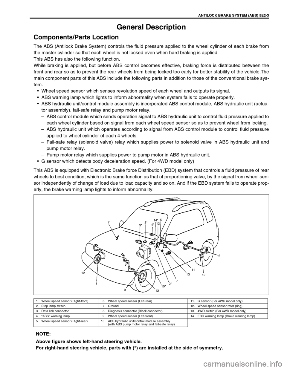
The ABS (Antilock Brake System) controls the fluid pressure applied to the wheel cylinder of each brake from
the master cylinder so that each wheel is not locked even when hard braking is applied.
This ABS has also the following function.
While braking is applied, but before ABS control becomes effective, braking force is distributed between the
front and rear so as to prevent the rear wheels from being locked too early for better stability of the vehicle.The
main component parts of this ABS include the following parts in addition to those of the conventional brake sys-
tem.
Wheel speed sensor which senses revolution speed of each wheel and outputs its signal.
ABS warning lamp which lights to inform abnormality when system fails to operate properly.
ABS hydraulic unit/control module assembly is incorporated ABS control module, ABS hydraulic unit (actua-
tor assembly), fail-safe relay and pump motor relay.
–ABS control module which sends operation signal to ABS hydraulic unit to control fluid pressure applied to
each wheel cylinder based on signal from each wheel speed sensor so as to prevent wheel from locking.
–ABS hydraulic unit which operates according to signal from ABS control module to control fluid pressure
applied to wheel cylinder of each 4 wheels.
–Fail-safe relay (solenoid valve) relay which supplies power to solenoid valve in ABS hydraulic unit and
pump motor relay.
–Pump motor relay which supplies power to pump motor in ABS hydraulic unit.
G sensor which detects body deceleration speed. (For 4WD model only)
This ABS is equipped with Electronic Brake force Distribution (EBD) system that controls a fluid pressure of rear
wheels to best condition, which is the same function as that of proportioning valve, by the signal from wheel sen-
sor independently of change of load due to load capacity and so on. And if the EBD system fails to operate prop-
erly, the brake warning lamp lights to inform abnormality.
1. Wheel speed sensor (Right-front) 6. Wheel speed sensor (Left-rear) 11. G sensor (For 4WD model only)
2. Stop lamp switch 7. Ground 12. Wheel speed sensor rotor (ring)
3. Data link connector 8. Diagnosis connector (Black connector) 13. 4WD switch (For 4WD model only)
4.“ABS” warning lamp 9. Wheel speed sensor (Left-front) 14. EBD warning lamp (Brake warning lamp)
5. Wheel speed sensor (Right-rear) 10. ABS hydraulic unit/control module assembly
(with ABS pump motor relay and fail-safe relay)
NOTE:
Above figure shows left-hand steering vehicle.
For right-hand steering vehicle, parts with (*) are installed at the side of symmetry.
Page 130 of 656
ANTILOCK BRAKE SYSTEM (ABS) 5E2-5
Diagnosis
To ensure that the trouble diagnosis is done accurately and
smoothly, observe “PRECAUTIONS IN DIAGNOSING TROU-
BLES” and follow “ABS DIAGNOSTIC FLOW TABLE”.
Precautions in Diagnosing Troubles
If the vehicles was operated in any of the following ways,
ABS warning lamp may light momentarily but this does not
indicate anything abnormal in ABS.
–The vehicle was driven with parking brake pulled.
–The vehicle was driven with brake dragging.
–The vehicle was stuck in mud, sand, etc.
–Wheel spin occurred while driving.
–Wheel(s) was rotated while the vehicle was jacked up.
Be sure to read “PRECAUTIONS FOR ELECTRONIC CIR-
CUIT SERVICE” in Section 0A before inspection and
observe what is written there.
Be sure to use the trouble diagnosis procedure as described
in the flow table. Failure to follow the flow table may result in
incorrect diagnosis. (Some other diagnosis trouble code may
be stored by mistake in the memory of ABS control module
during inspection.)
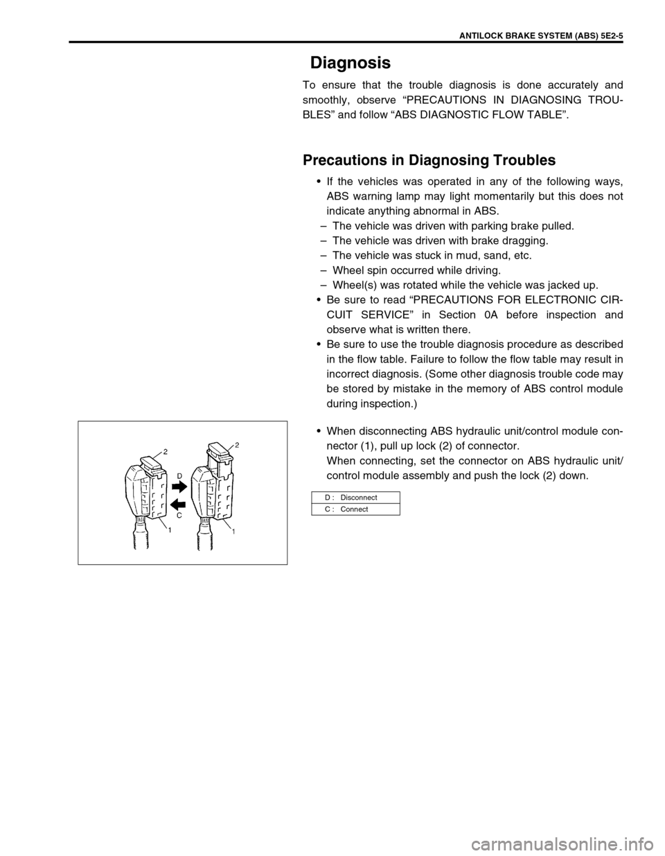
When disconnecting ABS hydraulic unit/control module con-
nector (1), pull up lock (2) of connector.
When connecting, set the connector on ABS hydraulic unit/
control module assembly and push the lock (2) down.
D : Disconnect
C : Connect